Table of Contents
Advertisement
Advertisement
Table of Contents

Subscribe to Our Youtube Channel
Related Manuals for Rinnai Energysaver RHFE-556T


Summary of Contents for Rinnai Energysaver RHFE-556T
- Page 1 Installation and User Manual RHFE-556T RHFE-556T Energysaver Space Heater Operation and Use - Page 2 Installation - Page 12 Important. Read these instructions carefully before attempting installation or use of this appliance. All work must be carried out by competent persons.
-
Page 2: Table Of Contents
Operation ......7 Adjusting Temperature ..8 Humidifier......9 Wiring Diagram ....23 Gas Conversion .....24 Extension Kits ....28 Service Contact Point ..33 Rinnai Corporation - Japan Manufactured under a Quality System Certified as complying with ISO 9001 by an Accredited Certification Body. ISO 9001... -
Page 3: Warranty
RINNAI WARRANTY OF QUALITY As the purchaser of this high quality model RHFE-556T product you are provided with the following warranty: Free Parts Heat Exchanger 15 Years 1 Year All other parts 1 Year * Full Heat Exchanger replacement (parts only) for all 15 years. -
Page 4: Layout Of Appliance
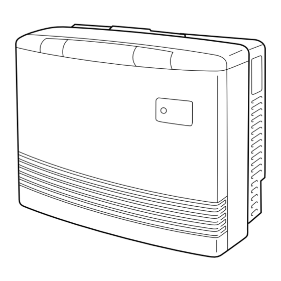
GETTING TO KNOW YOUR NEW RHFE-556T INDICATOR PANEL CONTROL PANEL ON-OFF Room Temp. Control HUMIDIFIER TRAY Built into the warm air discharge duct. Humidifies the warm air flow. LOUVRE Warm air discharge duct. BOTTOM TRIM Pulls off to allow filling of humidifier tray. -
Page 5: Control Panel Layout
CONTROL PANEL LAYOUT POWER ON / COMBUSTION INDICATOR FILTER INDICATOR Indicates that the appliance is turned ON and Indicates that the filter whether the burner is alight. needs cleaning. – 3 –... -
Page 6: Features
FEATURES FORCED FLUE SYSTEM PUSH BUTTON IGNITION Air for combustion is taken from outside the Only one touch of the ON/OFF switch is room and the flue products are exhausted required to operate the heater. outside, keeping the room air clean. WARM AIR DISCHARGE Warm air flows from the bottom of the appliance through the louvres, assisting in... -
Page 7: Safety Points
SAFETY POINTS Do not restrict the warm air discharge by This appliance must not be used for any placing articles in front of the heater. purpose other than heating. Do not spray aerosols whilst the heater is Flue Guard must be fitted if indicated on page operating. - Page 8 SAFETY POINTS Keep flammable materials, trees, shrubs, etc, Do not allow anyone to post articles through away from the flue terminal. the louvres. Gasoline LPGAS Filter should be cleaned at regular intervals. It is strongly recommended that a guard is fitted around heater where there are young children, elderly, infirm or handicapped persons.
-
Page 9: Operation
OPERATING YOUR NEW RHFE-556T I TO OPEN THE CONTROL PANEL Open Control Panel Cover with key provided. I TURNING ON (For manual operation please refer to page 21). Press the ON/OFF button to operate the heater. The ON indicator will glow green. After approximately 20... -
Page 10: Adjusting Temperature
ROOM TEMPERATURE ADJUSTMENTS POWER ON / COMBUSTION INDICATOR FILTER INDICATOR Indicates that the appliance is turned ON and Indicates that the filter whether the burner is alight. needs cleaning. – 8 –... -
Page 11: Humidifier
I HUMIDIFIER TRAY So that you can humidify the air, your Rinnai RHFE-556T is fitted with an enamelled tray at the bottom of the heater. If you choose to make use of the humidifier tray, it will need filling about once a day during the heating season. - Page 12 Power Surge Safety Device Overheat Safety Device Fan Delay Safety Device Your RHFE-556T requires very little maintenance, simply clean the rear fan filter once a week and wipe the outer case and louvre section with a damp cloth. DO NOT USE SOLVENTS.
- Page 13 Heater will not re-ignite after overheating. Even after unit has cooled down the heater does not ignite again. Repair is necessary. Contact your local agent or Rinnai for a Service call. I When the unit is turned off: Convection fan continues to run after turning This is to remove the residual heat from the heat OFF.
- Page 14 In all cases, you may be able to clear the Error Message simply by turning the heater OFF, then ON again. If the Error Message still remains or returns on the next operation contact Rinnai UK Ltd or your Supplier and arrange for a service call.
-
Page 15: Installation Instructions
INSTALLATION INSTRUCTIONS Important Safety Instructions 1. Gas Safety (Installation & Use) Regulations 1998 are the ‘Rules in Force’. In your own interest and that of safety, it is law that all gas appliances shall be installed by competent persons in accordance with the above regulations. Failure to install appliances correctly could lead to prosecution. - Page 16 Refer to local gas authority for confirmation of gas type if in doubt. Refer to data plate located on the right hand side. Check for damage, if the unit is damaged contact Rinnai. Do not install a damaged unit before checking with your supplier.
- Page 17 LOCATION When positioning the heater the main points This heater is not designed to be built in. governing the location are: 1. Flueing 2. Warm air distribution This heater must not be installed where curtains or other combustible materials could come into contact with it.
- Page 18 INSTALLATION FLUE this unit can only be used with one of the six types MANIFOLD. of Rinnai flue kits. Diagram below shows minimum clearances and Do not flue unit into other rooms. distances from obstructions. Also check local Flue terminal must be outside.
- Page 19 POSITIONING THE FLUE TERMINAL Dimension Terminal Position Distance Directly below an opening, air brick, opening windows, etc. 300mm Above an opening, air brick, opening window, etc. 300mm Horizontally to an opening, air brick, opening window, etc. 300mm Below gutters, soil pipes or drain pipes. 75mm Below eaves.
- Page 20 FLUE MANIFOLD POSITION. FLUE EXTENSION KITS Centre of hole for flue manifold can be drilled Flue extension Kits are available to allow longer anywhere within the shaded area. (To avoid studs flueing lengths. Contact Rinnai for information. etc.) – 18 –...
-
Page 21: Sleeve And Manifold Installation
SLEEVE AND MANIFOLD INSTALLATION METHOD FOR STANDARD WALLS 1. Dis-assemble Manifold from Sleeve. The flue consists of 3 parts, sleeve, inside connectors and tube, outside terminal; (dis- assemble by pulling hard on outside terminal and inner connections, then pull sleeve off outer terminal). - Page 22 SLEEVE AND MANIFOLD INSTALLATION METHOD FOR STANDARD WALLS 5. Check rubber seal is in place on terminal. Terminal seal 6. Installation of Terminal "TOP" mark "A" Label From outside, insert terminal into sleeve with the “A” mark at the top. Left hand side fixing tie is marked “LEFT”...
-
Page 23: Fitting Unit
FITTING UNIT AIR INLET HOSE 2. Fit the locking clamp over connection between sliding tube and manifold. Engage the hook and rotate it until it snaps against the body of the clamp. Manifold Manifold Inlet hose Flue outlet Sliding tube Hose clip Hook Detail of Hose clip... -
Page 24: Connecting Gas And Electrical Services
ON / OFF switch and adjust thermostat as required. Disconnect 2. For central timer control, a transformer kit is required. See price list or contact Rinnai for advice. 3. For use in Offices or Schools etc. where all heaters are connected to a central control... -
Page 25: Wiring Diagram
RINNAI 1004T/556T WIRING DIAGRAM USING RANDALL 851 PROGRAMMER – 23 –... -
Page 26: Gas Conversion
GAS CONVERSION CAUTION RISK OF ELECTRIC SHOCK ❈ Disconnect electrical supply 1. Remove bottom trim (pull) 2. Remove 8 screws inside bottom louvre, pull complete front panel forward at bottom, unclip from escucheon panel and remove from heater 3. Replace small gas label on gas inlet. 4. - Page 27 TESTING PRESSURE CHECKING PROCEDURE: Caution- 230 V inside appliance. SW6 DIP SWITCH 1. Check that SW6 (Dip switches) are correct for the gas ON OFF OFF type for which the appliance is to be used. (Refer to 556T diagram opposite). OFF OFF OFF 2.
- Page 28 I INSTRUCT CUSTOMER ON USE OF HEATER When you are satisfied that the appliance is operating correctly, explain operation of heater to the customer. FAULT-FAILURE PROCEDURE If unable to get the heater to operate correctly contact Rinnai. – 26 –...
-
Page 29: Wiring Diagram
BLOCK AND WIRING DIAGRAM WIRING DIAGRAM ON/OFF BUTTON SW6. DIP SWITCH SW1 FM. ADJUST SWITCH Hi INDICATOR SW2 FM. ADJUST SWITCH Lo bk bk SW3 POV. PRESSURE ADJUST SWITCH Hi SUB-P.C.B SW5. TEST SWITCH OPERATION P.C.B SW4 POV. PRESSURE ADJUST SWITCH Lo 1 2 3 SHORT CIRCUIT PATTERN bl bl bl... -
Page 30: Extension Kits
FORCED FLUE HEATER EXTENSION KITS EXTENSION KIT PARTS AND INSTALLATION GUIDE FOT - 155 0.5m EXTENSION KIT FOT - 156 1.0m EXTENSION KIT FOT - 157 2.0m EXTENSION KIT FOT - 158 BENT ELBOW KIT FOT - 160 LONG FLEX TUBE 600 KIT •... -
Page 31: How To Install
IMPORTANT NOTE: When the appliance is installed using a flue extension that exceeds 1.8 metres you must change the link on the flue extension terminal block as shown. Terminal is located at the rear of unit FOR DIRECT EXHAUST next to gas inlet. USED FOR EXTENSION KITS I TYPES COMPATIBLE WITH EXTENSION KIT RHFE - 556FTR / 556T... - Page 32 1. How to connect exhaust pipes Exhaust pipe Exhaust pipe Fit inside Male end Male end Female end Female end Pipe stopper B Pipe stopper B Pipe stopper A To connect the exhaust pipes, fit the male end into the female end and clamp with pipe stopper A to prevent slipping.
- Page 33 I CAUTIONS 1. Maximum extendable length 2. To prevent water condensation FOR BEST ROOM AIR HUMIDITY, KEEP Condensed water WATER IN THE HUMIDIFIER TRAY. may accumulate here, and cause a blockage preventing combustion. MAXIMUM FLUE LENGTH 7 METRES. Reduce length 1 metre for each bend used. CAUTION (e.g.
- Page 34 4. Wherever the air intake hose and exhaust pipe run sideways, try to have the exhaust pipe on top (to prevent the air intake hose from sagging onto the exhaust pipe). Exhaust pipe Exhaust pipe Air intake hose Air intake hose –...
-
Page 35: Service Contact Point
DIMENSIONS SERVICE CONTACT POINT Contact: Rinnai UK Ltd. 9 Christleton Court Manor Park Runcorn WA7 1ST Tel: 01928 531870 Fax: 01928 531880 www.rinnaiuk.com – 33 –... - Page 36 Jan 2006 556F-2190...
Need help?
Do you have a question about the Energysaver RHFE-556T and is the answer not in the manual?
Questions and answers