Table of Contents
Advertisement
Quick Links
Advertisement
Table of Contents

Related Manuals for Ducati MONSTER 400


Summary of Contents for Ducati MONSTER 400
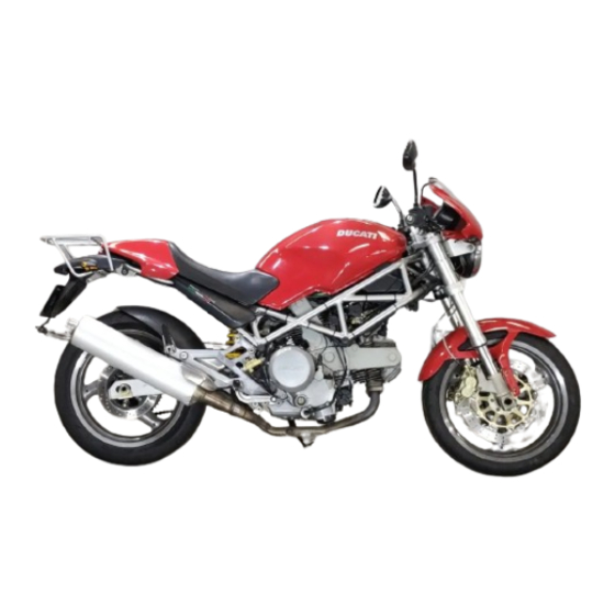
- Page 1 Owner’s manual...
- Page 3 Ducati motorcycle for long information contained herein is valid at the time of going journeys as well as short daily trips. Ducati Motor s.p.a to print. Ducati Motor S.p.A. reserves the right to make wishes you smooth and enjoyable riding.
-
Page 4: Table Of Contents
TABLE OF CONTENTS Main components and devices Location 18 Tank filler plug 19 Seat catch and helmet pin 20 Side stand 21 Shock absorber adjusters 22 Directions for use Running-in recommendations 23 General Pre-ride checks 25 Warranty 6 Starting the engine 26 Symbols 6 Moving off 28 Useful information for safe riding 7... - Page 5 Chain lubrication 43 Replacing bulbs 43 Headlamp alignment 46 Tyres 47 Checking engine oil level 48 Cleaning and replacing the spark plugs 49 Cleaning the motorcycle Storing the bike away Important notes 51 Technical data Overall dimensions 52 Weights 52 Top-ups 53 Engine 54 Timing system 54...
-
Page 6: General
Ducati Motor S.p.A. advises you to read this booklet carefully so as to become familiar with your motorcycle. In case of any doubts, please call a Ducati dealer or authorized workshop. The information contained herein will prove useful on your trips - and Ducati Motor S.p.A. -
Page 7: Useful Information For Safe Riding
Useful information for safe riding lane in good time using the suitable turn indicators. Be sure you are clearly visible and do not ride within the Warning blind spot of vehicles ahead. Read this section before riding your motorcycle. Be very careful when tackling road junctions, or when riding in the areas near exits from private grounds, car Accidents are frequently due to inexperience. -
Page 8: Carrying The Max Load Allowed
Carrying the maximum load allowed Your motorcycle is designed for long-distance riding, carrying the maximum load allowed in full safety. Even weight distribution is critical to preserving these safety features and avoiding trouble when performing sudden manoeuvres or riding on bumpy roads. Information about carrying capacity The total weight of the motorcycle in running order including rider, pillion passenger, luggage and additional... -
Page 9: Identification Data
Identification data All Ducati motorcycles have two identification numbers, for frame (fig. 1.1) and engine (fig. 1.2). Frame number Engine number Note These numbers identify the motorcycle model and should always be indicated when ordering spare parts. fig. 1.1 fig. 1.2... -
Page 10: Controls
CONTROLS Warning This section details the position and function of all the controls you need to drive your motorcycle. Be sure to read this information carefully before you use the controls. Position of motorcycle controls (fig. 2) 1) Instrument panel. 2) Key-operated ignition switch and steering lock. -
Page 11: Instrument Panel
Instrument panel (fig. 3) 1) Speedometer (km/h or mph). Gives road speed. a) Odometer (km or miles). Gives total distance covered. b) Trip meter (km or miles). Gives distance covered since last resetting. c) Trip meter resetting knob. Turn to reset trip meter to “0000”. 2) Green light N. -
Page 12: Keys
Keys (fig. 4) Ignition switch and steering lock (fig. 5) Your Ducati was delivered with two universal keys for It is located in front of the fuel tank and has four ignition, steering lock and seat catch and a key positions: identification plate (1). -
Page 13: Left Switch
Left switch (fig. 6) 1) Switch, light switch, 3 positions: Down = light off; Centre = front and rear parking light, number plate light and panel lights on; = headlamp, front and rear parking light, number plate light and panel lights on. Note This device is not fitted on the Australia and Japan versions. -
Page 14: Clutch Lever
Clutch lever (fig. 7) Cold start lever (fig. 8) When you pull in the lever (1), you will disengage the Use this device to start the engine from cold. It will engine from the gearbox and therefore from the driving increase the engine idling speed after starting. -
Page 15: Right Switch
Right switch (fig. 9) Front brake lever (fig. 9) 1) Switch for ENGINE STOP, two positions: Pull in the lever (4) towards the twistgrip to operate the position (RUN) = run. front brake. The system is hydraulically operated and you position (OFF) = stop. -
Page 16: Rear Brake Pedal
Gear change pedal (fig. 11.1) Rear brake pedal (fig. 10) The gear change pedal is at rest when in the central Push down on the pedal (1) to apply the rear brake. position N, is moved up and down to change gears and The system is hydraulically operated. -
Page 17: Setting The Gear Change And Rear Brake Pedals
Setting the gear change and rear brake pedals (fig. 11.2, 11.3) The gear change and rear brake pedals can be adjusted to suit the preferred riding position of each rider. To set the gear change pedal, lock linkage (1) and loosen the check nuts (2) and (3). Note Nut (2) has a left-hand thread. -
Page 18: Main Components And Devices
MAIN COMPONENTS AND DEVICES Location (fig. 12) 1) Tank filler plug. 2) Seat catch. 3) Hook for helmet fastening cable. 4) Passenger grab handle. 5) Side stand. 6) Rear view mirrors. 7) Shock absorber adjusters. 8) Fuel tank lifting rod. 9) Seat cover. -
Page 19: Tank Filler Plug
Tank filler plug (fig. 13) Opening Lift the protection lid (1) and fit the ignition key into the lock. Turn the key clockwise 1/4 turn to unlock. Lift the plug. Closing Refit the plug with the key in it and push it down into its seat. -
Page 20: Seat Catch And Helmet Pin
Seat catch and helmet pin Opening Fit the ignition key into the lock. Turn the key clockwise to detach seat from frame. Pull the seat backwards to slide it off its front holders. On the rear end of the compartment underneath the seat, there is the helmet fastening cable (1) (see page 31). -
Page 21: Side Stand
Side stand (fig. 15) Note Check for proper operation of the stand mechanism Important (two springs, one into the other) and the safety sensor Before lowering the side stand, make sure that the (2). bearing surface is hard and flat. Warning Do not park on soft or pebbled ground or on asphalt melt The motorcycle can be started only if the side stand... -
Page 22: Shock Absorber Adjusters
Shock absorber adjusters (fig. 16) The shock absorber has outer adjusters that enable you to adjust your motorcycle to the load. The adjuster (1) located on the right side, on the connection holding the shock absorber to the swingarm, controls rebound damping. Turn the adjuster (1) clockwise to increase damping (H), anticlockwise to reduce it (S). -
Page 23: Directions For Use
Warranty validity. Failure to comply with these rules meter under control. The indicator must not exceed: will release Ducati Motor S.p.A. from any liability speed as indicated for the each gear (fig. 17.1). whatsoever for resulting engine damage or shorter During the first hours of riding, it is advisable to run the engine life. - Page 24 After 2500 km/1553 miles 5ª After running-in, never exceed the following values during the motorcycle standard use: 4ª max. speed allowed for each gear (see page 55). Strict observance of running-in recommendations will 3ª ensure longer engine life and reduce the likelihood of overhauls and tune-ups.
-
Page 25: Pre-Ride Checks
Pre-ride checks Warning In case of malfunctioning, do not start the Warning motorcycle and call a Ducati dealer or authorized Failure to carry out these checks before riding, may workshop. lead to motorcycle damage and injury to rider and passenger. -
Page 26: Starting The Engine
Starting the engine 3) Check that the stop switch (1, fig. 18.3) is positioned (RUN), then press the starter button (2). Note Let the engine start without using the throttle control. Follow the “High ambient temperature” procedure to start the engine when it is warm (page 27). Important Never operate the starter more than 5 seconds at a Warning... - Page 27 High ambient temperature (over 35 °C/95 °F): Follow the same procedure, however, do not use the fast-idle device. Cold ambient temperature (below 10 °C/50 °F): Follow the procedure for “Regular ambient temperature”, however allow 5 minutes for the engine to warm up (step 5).
-
Page 28: Moving Off
Moving off Braking 1) Disengage the clutch squeezing the control lever. Slow down in time, shift down to engine-brake first and 2) Push down on gear change lever sharply with the tip then brake applying both brakes. Pull the clutch lever of your foot to engage the first gear. -
Page 29: Stopping The Motorcycle
Stopping the motorcycle Refueling Slow down gradually, then shift down and release the Never overfill the tank when refueling. Fuel should never throttle twistgrip. Finally change from first to neutral. be touching the rim of filler recess (fig. 20). Apply brakes and you will bring the motorcycle to a complete stop. -
Page 30: Parking
Parking Stop the motorcycle, then put it on the side stand to park it (see page 21). To avoid theft, turn the handlebar fully left and turn the key to LOCK position. If you park in a garage or other facilities, make sure that there is proper ventilation and that the motorcycle is not near a source of heat or sparks. -
Page 31: Maintenance
MAINTENANCE Tool kit and accessories (fig. 22.1) The compartment under the seat holds: an Owner’s manual; a helmet fastening cable; a tool bag for normal maintenance and checks to be performed by the user. fig. 22.1 To reach this compartment, remove the seat first (page 20) then the protective cover (1). -
Page 32: Routine Maintenance
)This symbol indicates that the job in question should operations to be carried out at regular intervals according be entrusted to a Ducati Dealer or authorized workshop to time (months) or distance covered (km or miles). It where highly trained personnel and special equipment also shows the motorcycle parts requiring special care. - Page 33 Operations Pre- After 1000 km/ Every Every Every delivery 621 miles 1000 km/ 10000 km/ 20000 km/ or 6 months 621 miles 6,214 miles 12,427 miles Spark plugs Carburettor: synchronization and idling adjustment ( ) Chain: tensioning and lubrication ( ) C/ L C/ L C/ L...
- Page 34 Operations Pre- After 1000 km/ Every Every Every delivery 621 miles 1000 km/ 10000 km/ 20000 km/ or 6 months 621 miles 6,214 miles 12,427 miles Valve clearance ( ) Rear wheel rubber cush drive damper ( ) Signaling and light system Battery liquid level General lubrication ( ) Clutch and brake control oil ( )
-
Page 35: Main Maintenance Operations
MAIN MAINTENANCE OPERATIONS Lifting the fuel tank (fig. 23.1) Warning Make sure the fuel in the tank is less than 5 litres/1.3 US.Gal. or fuel may leak out through the filler plug breather. fig. 23.1 Remove the seat (page 20) and lift the hook (1). Lift the tank and unhook the service rod (2, fig. -
Page 36: Changing Air Filter
Changing air filter (fig. 24.1) Replace the air filter at the required intervals shown in the routine maintenance chart. The air box is accessible after lifting the fuel tank as described on page 35. To remove the filter, release the cover clips (1) on both sides of the air box and take off the cover (2). -
Page 37: Checking Brake And Clutch Fluid Level
Brake system If you find exceeding play on brake lever or pedal and brake pads are still in good condition, contact your Ducati dealer or an authorized workshop to have the system inspected and any air drained out of the circuit. -
Page 38: Checking Brake Pads For Wear
Rear brake Friction material on each pad must be at least 1 mm/0.039 in. thick. Important Have the brake pads replaced at your Ducati Fig.26 dealer's shop or authorized workshop. -
Page 39: Lubricating Cables And Joints
Work the controls to make sure the cable slides smoothly inside the sheath: if you feel any friction or hard spots, have the cable replaced by your Ducati dealer or authorized workshop. To prevent these failures, smear the ends of the flexible cables with SHELL Advance Grease or Retinax LX2 at regular intervals. -
Page 40: Throttle Cable Adjustment
Throttle cable adjustment Checking battery liquid level (fig. 29) The throttle twistgrip must have a free play of 2 - 4 Lift the tank to carry out such operation (page 35). mm/0.08-0.16 in., measured at the edge of the twistgrip Battery liquid level must be maintained between the and at all positions of the handlebars. -
Page 41: Charging The Battery
Charging the battery (fig. 29) Refit the caps (1) on the cells and reinstall the battery on Before charging the battery, it is best to remove it from its mount and clamp the retainers (3). the motorcycle. Reconnect the breather tube (2) and connect the Disconnect the breather tube (2). -
Page 42: Chain Tensioning
Chain tensioning Turn the rear wheel slowly until you find the position where chain tension is highest. With the motorcycle on the side stand, push the chain up pressing with a finger at the point where it intersects with swing arm centerline. The lower portion of the chain should have a slack as follows (fig. -
Page 43: Chain Lubrication
Chain lubrication Replacing bulbs The chain fitted on your motorcycle has OR seals that Before replacing a burnt-out bulb, make sure that the keep dirt out of and lubricant inside the sliding parts. The new one complies with voltage and wattage as specified seals might be irreparably damaged if the chain is on page 58 - “Electric System”. - Page 44 Note Instrument panel (fig. 32) Never touch the transparent body of the new bulb Disassemble the instrument panel by unscrewing the with your fingers or it will blacken resulting in reduced two fastening screws (1) with washer (2). bulb brilliancy. Disconnect the odometer cable (3) and the main wiring Insert the locating pegs of the bulb base into their seats connector (4).
- Page 45 Turn indicators (fig. 33) Stop light (fig. 34) Remove the screw (1) and detach the glass (2) from the To replace the stop and parking light bulb, unscrew the body. two screws (1) that secure the glass (2). Remove the The bulb is of the bayonet-type: press and rotate anti- glass.
-
Page 46: Headlamp Alignment
Headlamp alignment (fig. 35.1) When checking headlamp alignment, put the motorcycle upright. Tyres should be inflated at the correct pressure and one person should be sitting astride the motorcycle, keeping it at right angles to its longitudinal axis and opposite a wall or a screen, 10 meters/393.7 in. apart from it. -
Page 47: Tyres
After replacing a tyre, the wheel should be balanced. Important Do not remove or shift the wheel balancing weights. Note If tyres need replacing, contact a Ducati Dealer or authorized workshop to make sure wheels are removed and refitted correctly. -
Page 48: Checking Engine Oil Level
Remove any stones or other foreign bodies caught in the tread. Important Engine oil and oil filters must be changed by a Ducati dealer or authorized workshop at regular intervals, as specified in the routine maintenance schedule. Viscosity SAE 20W-50... -
Page 49: Cleaning And Replacing The Spark Plugs
If color has altered or you find any dark deposits, change the spark plug and report this to a Ducati dealer or authorized workshop. Check wear on the central electrode. If it looks worn out or has a vitreous appearance, change the spark plug. -
Page 50: Cleaning The Motorcycle
Important Cleaning the motorcycle If the gap needs adjusting, be very careful when To preserve the finish of metal parts and paintwork, wash bending the side electrode. If gap is too wide or too and clean your motorcycle at regular intervals, anyway close, engine performance will be affected. -
Page 51: Storing The Bike Away
Carry out any required inspection at regular intervals and plug with its seal and empty the fuel tank; replace any parts using Ducati original spare parts pour a few drops of engine oil into the cylinders through complying with local law. -
Page 52: Technical Data
TECHNICAL DATA Weights Dry weight: 174 Kg / 384 lb. Carrying full load: 318 Kg / 701 lb. Warning Failure to observe weight limits could result in poor Overall dimensions (mm/in.) (fig. 39) handling and impair the performance of your motorcycle, and you may lose control of the motorcycle. -
Page 53: Top-Ups
Top-ups Type of fluid cu. dm. (liters)/ US Gall. Fuel tank, including a reserve Gasoline 95-98 RON 16.5 of 3.5 cu dm (liters) / 0.92 US Gall. Oil sump and oil filter SHELL Advance Ultra 4 3.1 / 0.82 Front/Rear brake and clutch circuits SHELL-Advance Brake DOT 4 –... -
Page 54: Engine
Timing system Engine Desmodromic (type) with two valves per cylinder, Twin cylinder, four-stroke, 90° “L” type, longitudinal. operated by four rockers (2 opening rockers and 2 closing Bore mm/in.: rockers) and an overhead camshaft. It is operated by the 70.5 / 2.78 crankshaft through spur gears, belt rollers and toothed Stroke mm/in.: belts. -
Page 55: Performance Data
The figure shows the maximum speed limits that can be reached in each individual gear after the running-in period. Important Failure to comply with these limits releases Ducati fig. 41 Motor S.p.A. from any liability whatsoever for resulting engine malfunction. -
Page 56: Brakes
Wash the affected area with abundant running However, if you wish to tune up your motorcycle for water. competitive trials, you may refer to Ducati Motor S.p.A. who will be glad to provide information about the special... -
Page 57: Frame
Tubeless, radial tyre. Warning Size: 120/60-VR17. If the rear sprocket needs replacing, contact a Ducati Dealer or an authorized workshop. If improperly Rear tyre replaced, this component could seriously endanger your Tubeless, radial tyre. safety and that or your passenger, and cause irreparable Size: 160/60-VR17. -
Page 58: Electric System
Electric system Fuses Basic electric items are: The fuse box is located under the seat. Round headlamp with iodine double filament bulb, 12V- To expose the fuses, take off the box protective cover (1, 55/60W bulb. fig. 42.1). Mounting position and ampere capacity are Parking light with 12V-5W bulb. - Page 59 fig. 42.3 fig. 42.1 IN GOOD CONDITION BLOWN fig. 42.2...
- Page 60 Legend of the wiring diagram of electric 31) Starter motor system/ignition 32) Starter solenoid 1) Headlamp 33) Battery 2) Front right-turn indicator 34) Main relay 3) Front left-turn indicator 35) Heater 4) Horn 36) Thermal cutout 5) Number plate light 6) Odometer Wire color coding 7) Instrument panel warning lights...
- Page 61 Legend of fuse box (30) Pos. Description Rat. Main switch 30 A 2-10 Ignition, regulator 7.5 A 3-11 High and low beams 15 A 4-12 Turn indicators, warning lights, tail 7.5 A lights and instrument panel lights 5-13 Stop, warning horn 7.5 A 6-14 Carburetor heater...
-
Page 62: Monster Versions
- footpegs feature no rubber pads; - seat cover not supplied; - fuel tank comes in: Available in the following colors: - metallic grey; Ducati red 473.101; - metallic black; yellow 473.201; - metallic dark blue; metallized grey 291.601; - metallic purple;... -
Page 63: Routine Maintenance Record
Routine maintenance record km/miles Ducati Mileage Date Service Name 1,000/621 10,000/6,214 20,000/12,427 30,000/18,641 40,000/24,855 50,000/31,068... - Page 64 913.7.060.1E DUCATIMOTOR spa Stampato 01/2000 Via Cavalieri Ducati, 3 40132 Bologna, Italy Tel 39.051.6413111 Fax 39.051.406580 Internet: www.ducati.com...
- Page 65 G/Bk LOCK PARK R/BK – Bn/Bk YUASA B/Bk YB16AL-A2 R/BK 1 4 3 6 2 R/B BN 10 W 10 W W/Bn B/Bk V/BK Gr/R 5/21 W Y/BK W/BK W/BK 10 W 10 W W/BK B/Bk RELE’ SICUREZZE W/BK Y/BK G/BN Bn/Bk B/Bk...
Need help?
Do you have a question about the MONSTER 400 and is the answer not in the manual?
Questions and answers