
Related Manuals for ELECRAFT KX1


Summary of Contents for ELECRAFT KX1
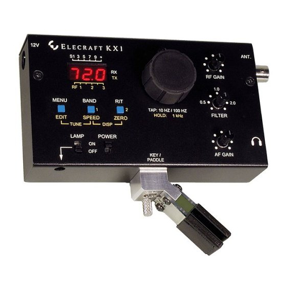
- Page 1 K X 1 L E C R A F T T R A N S C E I V E R K X 1 L E C R A F T ANT. RF GAIN MENU BAND TAP: 10 HZ / 100 HZ FILTER SPEED HOLD: 1 kHz...
- Page 2 L E C R A F T Ultra-Portable CW Transceiver Owner’s Manual Revision B, November 3, 2003 © Copyright 2003 Elecraft, All Rights Reserved Elecraft • www.elecraft.com P.O. Box 69 • Aptos, CA 95001-0069 (831) 662-8345 • Fax: (831) 662-0830...
-
Page 3: Table Of Contents
ASSEMBLY – PART II ....................................30 ALIGNMENT AND TEST - PART II ................................43 ASSEMBLY - PART III....................................48 ALIGNMENT AND TEST - PART III ................................58 FINAL ASSEMBLY ....................................60 OPERATION ......................................62 KX1 OPTIONS......................................71 CIRCUIT DETAILS.....................................72 PARTS LIST.....................................APPENDIX A SCHEMATIC ....................................APPENDIX B BLOCK DIAGRAM...................................APPENDIX C PHOTOGRAPHS..................................APPENDIX D TROUBLESHOOTING ................................ -
Page 4: Introduction
Additional operating features include instant band selection, nine standing. The KX1 is also at home on a table or desk, providing an frequency memories, three VFO tuning rates, receive incremental tuning optimal display viewing angle without the need for a tilt stand. -
Page 5: Technical Assistance
You problem. must send the unit at your expense to Elecraft, but we will pay return shipping. Repair Service... -
Page 6: Specifications
LECRAFT Specifications General Transmitter Size (H x W x D) Max. power output (approx.) Cabinet 1.2 x 5.3 x 3.0" (3 x 13.5 x 8 cm) 9 V supply 1.5-2 W Overall 1.4 x 5.8 x 3.0" (3.5 x 15 x 8 cm) 12 V supply 3-4 W Weight... -
Page 7: Preparation For Assembly
LECRAFT Preparation for Assembly Overview of the KX1 The KX1 chassis consists of a top and bottom cover (Figure 1). All components, including controls and connectors, are mounted on a single printed circuit board (PCB). Only three surface-mount components are required, and these are pre-mounted to the board. -
Page 8: Unpacking And Inventory
LECRAFT Unpacking and Inventory Preventing Electro-Static Discharge Damage Inventory Problems caused by Electro-Static Discharge (ESD) may be very We recommend that you do a complete inventory, using the parts lists difficult to troubleshoot because damaged components may still in Appendix A. operate somewhat rather than fail completely. - Page 9 LECRAFT Identifying Common Resistors and RF Chokes The color bands that indicate the value of each resistor are shown in If you sort out the inductors before starting assembly, you will be able the text to help you identify each part. However, it's helpful to to positively identify each inductor from the color bands listed in the familiarize yourself with the color code.
- Page 10 This can be determined from the color and and “...104” indicates 100,000 ohms (100K). size. Two types of cores are used in the KX1: Iron powder cores and ferrite cores. If you mix them up, your KX1 will not operate properly.
- Page 11 700 to 800°F tip (370-430°C). Recommend a spade tip approx. 0.05” (1.3 mm) wide. Do not use a high-wattage iron or soldering gun since this can damage pads, traces, or the Refer to www.elecraft.com for tool sources and solder parts themselves. recommendations.
- Page 12 LECRAFT Soldering and Desoldering Solder joints should be clean and shiny. If a joint appears dull or has fine cracks, it is probably cold. Cold solder joints should be cleaned Use adequate ventilation when soldering; avoid and re-soldered. First, use solder wick (desoldering braid) to remove inhaling smoke or fumes.
- Page 13 Invest in a PC board vice with a heavy base if possible. This makes parts removal easier because it frees up both hands. If in doubt about a particular repair, ask for advice from Elecraft or from someone else with PCB repair experience.
- Page 14 LECRAFT Assembly Notes Each step in the assembly process is accompanied by a check-box: IC Sockets Only one integrated circuit is mounted in a socket. Do not use a different type of socket. The one supplied is a low-profile socket that As you may have noticed already, the symbol below is used to alert provides just enough room for the case to fit together.
-
Page 15: Assembly - Part I
If you haven’t done so already, open the bag of components tested. Later sections cover receiver (Part II) and transmitter (Part III) labeled KX1 MAIN BAG and sort the parts into groups. Many of the assembly and test. components will be in small paper envelopes. Do not mingle the contents of one envelope with another. - Page 16 LECRAFT Bend the leads of resistor R8, 6.8k (blu-gry-red), 1/4 watt, at Bend the leads of resistor R28, 1.8k (brn-gry-red), 1/4 watt, to fit right angles close to the body. Insert the leads in the solder pad holes, in the holes indicated on the board. Note that the leads should NOT be and bend them out on a 45-degree angle on the opposite side of the bent close to the body of the resistor like you did for R8.
- Page 17 Find the outline for RP5 on the top of the circuit board. With the board face up so that KX1 is in the upper left corner, the outline for R12, 6.8k (blu-gry-red). RP5 is just to the left and above the notch at the center of the lower edge of the board.
- Page 18 LECRAFT Insert RP5 with Pin 1 of the pack in the round solder pad. The Locate resistor pack RP1, 390 ohms (391). RP1 is in a 16-pin DIP round pad is farthest from the edge of the board. package that looks much like an integrated circuit. The resistance elements run across the package (e.g.
- Page 19 LECRAFT Turn the board face up so KX1 is in the upper left corner. Locate Do not substitute a different socket for the one provided. the printed outlines for diodes D2 and D3 near the center of the left The very low profile of the supplied socket is required for the case edge of the board.
- Page 20 LECRAFT Turn the board face down so the printed outline for power Test fit a .1 µF (104) capacitor in the solder pad holes for C31. connector jack J1 is in the upper right corner. Use a ruler to verify that the top of the capacitor is no more than 5/16” (7.9 mm) above the board.
- Page 21 C31. bottom edge of the board. Turn the board top face up so that KX1 is in the upper left corner. Install the following capacitors between the socket for U1 and the In the following steps you will install several capacitors on the top of bottom edge of the board: side of the board.
- Page 22 LECRAFT Insert electrolytic capacitor C38 (10 µF, 35 v) with the longer lead Turn the board over so the top face is up and test-fit the low- profile crystal in the space provided for X1 near the bottom edge passing through the square solder pad with the (+) symbol next to it below the socket for U1.
- Page 23 LECRAFT Use a discarded component lead to ground the case of the crystal as follows: Solder one end of the lead in the ground hole near the edge of the board to on the left side of the crystal. Tin the top of the crystal nearest the lead with a small amount of solder.
- Page 24 LECRAFT Test-fit two-pin plug P1 directly below J1. Orient P1 so the Turn the board over so the top face is up with KX1 in the upper locking ramp that sticks up alongside the pins is on the side farthest left corner.
- Page 25 LECRAFT Test fit slide switch S2 along the edge of the board next to Voltage regulators U8 and U9 are installed in the following electrolytic capacitor C10. The switch can be oriented either way steps. These devices look very similar. Double check the markings around.
- Page 26 LECRAFT Install U9 (77L06) below RP5 on the lower edge of the board Install 3-digit LED display DS1 as follows: using the same procedure that you used for U8 above. Be sure the top Insert the 3-digit LED display in the space bounded by of the device is no more than 5/16”...
-
Page 27: Visual Inspection
LECRAFT Visual Inspection Resistance Checks Verify correct orientation (banded end) of diodes D2 and D3, Make the resistance checks listed below with your DMM’s using the parts placement drawing (Appendix F). negative (-) lead connected to the circuit board ground at the screw hole just above capacitor C6. -
Page 28: Alignment And Test - Part I
LECRAFT Alignment and Test - Part I In this section you’ll become familiar with basic KX1 operation, while Press down very firmly on U1. If it is not seated as far as testing the control and display functions. possible into its socket, the pins may not make good contact. - Page 29 Moving the VFO knob or operating one of the pushbutton switches will turn it on again. (The display time- The 2.7 V and 6 V regulators used in the KX1 (U7 and U9, out is programmable. This will be discussed in the next section.) respectively) are low-dropout types, which may oscillate if their bypass capacitors are defective or are of the wrong value.
- Page 30 1 k H z Accessing the Configuration Menu decimal point is displayed at this step size. to enter the KX1’s configuration menu. You should M E N U To select 10 Hz or 100 Hz steps, tap the VFO knob (i.e., tap see LED on the display, which is the first menu entry (display ).
-
Page 31: Assembly - Part Ii
Compare the color codes you find on each inductor with the list below. The color bands are very small. Use a magnifier as needed Position the board face up with KX1 in the upper left corner. to be sure of the colors. - Page 32 RP5. Orient the varactor according to the printed outline on the Turn the board face up with KX1 in the upper left corner. board. The varactor may have a beveled back instead of a rounded back as shown on the board (See Figure 10).
- Page 33 LECRAFT Install capacitor C2, 27 pF (270) between capacitor C55 and In the following steps you may be installing some diode D4 on the lower edge of the board. capacitors with leads closer together than the hole spacing in the circuit board.
- Page 34 LECRAFT Locate C45, 68 pF (68 or 680), LS 0.2. Be sure that you do not The following capacitors must be mounted closer to the confuse this capacitor with C56, also 68 pF but with 0.1” lead spacing, board than the others. They are installed in the area beneath the that has not been installed yet.
- Page 35 Turn the board over so jack J1 is in the upper right corner and Turn the board face up so that KX1 is in the upper left corner. locate the printed outline for C15 just to the left of electrolytic capacitor C17 at the center of the board.
- Page 36 LECRAFT Install electrolytic capacitor C53 (10 µF, 35 V) between diode D4 With the board face up so that KX1 is in the upper left corner, and capacitor C21 in the lower right corner of the board as follows: locate the printed outline for U4 on the right hand edge of the board below U3.
- Page 37 C9 over the pins for JFET Q2 (away from the large hole in the board). Turn the board face up with KX1 in the upper left corner and locate the printed outline for trimmer CA just above transistor Q7 and the upper right corner of encoder Z1.
- Page 38 LECRAFT Install trimmer CA as follows: Open the package for four crystals: X2, X3, X4 and X5. The four crystals are identical. Place a red trimmer in the CA position with the flat side of the trimmer over the flat side on the printed outline. While installing crystals in the following steps, be careful Press the trimmer down against the board and spread the pins not to flow too much solder onto the leads.
- Page 39 If you fitted your soldering iron with a larger tip to install J2, replace it with a fine tip now. Turn the board face up with KX1 in the upper left corner. Fit headphone jack J4 in the printed outline in the lower right corner.
- Page 40 LECRAFT Turn the board top face up with KX1 in the upper left corner. The optional KXAT1 ATU module plugs directly into connectors J6, J7, and J8, which you’ll install in the following Install potentiometer R2 (B10K) as follows: steps. They MUST be positioned vertically (not tilted) or the ATU module cannot be installed.
- Page 41 Match the winding direction shown in the figure or the leads won’t line up with the solder pads on the circuit board. Spread the turns around the core so the finished result looks like Figure 16. Prewound toroids are available from an Elecraft-approved source. See www.elecraft.com for details.
- Page 42 LECRAFT Strip the insulation and tin the leads of both inductors using one Pull the leads tight so the toroid is sitting upright and against the of the following techniques: board. Check to see that some tinned lead is visible above the pad near the toroid when the wire is pulled tight.
- Page 43 LECRAFT Visual Inspection Your kit includes an extra 22 k resistor (red-red-orange) for use at R32. This resistor is not present on the Revision B or B1 PC Verify correct orientation (banded end) of diode D4, using the boards. It must be soldered in place in the location shown below, parts placement drawing (Appendix F).
-
Page 44: Alignment And Test - Part Ii
You should hear B AN D relays K1 and K2 switching. Due to the small size of the KX1’s front panel, knobs are not appropriate for use on the RF GAIN, FILTER and AF GAIN If necessary, use again to return to 7 MHz. - Page 45 S P E E D meter has not been calibrated. (The SIG menu entry is used for this Tap any switch to return to the frequency display. (The KX1 does not purpose; it is described later.) transmit when adjusting the keyer speed.) Hold together again to select voltmeter mode.
-
Page 46: Receiver Alignment
In all cases, use a signal that is weak enough to not activate BOTTOM OF BOARD the KX1’s AGC; otherwise, it will be much more difficult to find the correct settings for the trimmer capacitors. If you use a transmitter, be Figure 17. - Page 47 AGC and S-Meter Test The trimmer access holes on the revision B and B1 KX1 PC boards are plated through and grounded. This may make Turn the KX1 on and connect an antenna or signal generator.
- Page 48 10 or 20 Hz using the BFO and DDS menu entries. To check the current drain, set your DMM for DC milliamps and temporarily insert the DMM in series between the KX1 and the power While it is possible to do operating frequency calibration at this time, supply.
-
Page 49: Assembly - Part Iii
Install trimmer potentiometer R4, 100 ohms (101), next to diode D7 and resistor R30 as follows: Turn the board top face up with KX1 in the upper left corner. Install the following 1/4 watt resistors to the upper left of encoder Z1: Position R4, 100 ohms (101), and hold it in place while tack- soldering one pin. - Page 50 LECRAFT Turn the board top face up with KX1 in the upper left corner. In the following steps you’ll wind and install toroidal Install the following capacitors in the area above encoder Z1. Be sure inductors L3 and transformer T1. They must be wound as exactly to check the each capacitor to ensure it is no more than 5/16”...
- Page 51 LECRAFT Wind toroidal inductor L3 on one of the FT37-43 cores as follows: Cut an 8” (20 cm) length of red enameled wire. “Sew” the long end of the wire through the hole in the core for a total of 6 turns. Match the winding direction shown in Figure 18.
- Page 52 LECRAFT Install toroidal inductor L3 and solder both leads. Check for Place the front panel (top cover) face down on a soft cloth to continuity (less than 1 ohm) between the solder pads. avoid scratching it. Remove the paint from around the screw holes where the short Do NOT attach L3 or T1 to the circuit board with adhesive standoffs will contact the front panel as shown in .
- Page 53 LECRAFT Locate the thermal pad. Leave it on the backing paper while you Position the red filter over the LED display opening. Use the remove the piece filling the hole near one end. Then remove the clear tape to secure it on the top and bottom edges as shown in Figure backing and place the pad on the inside of the cover over the area you 23.
- Page 54 LECRAFT In the following steps you will install power amplifier transistor Locate the silk-screened outline for Q6 at the top edge of the Q6 (2SC2166). Q6 is mounted so that the front panel (top cover) will circuit board. Install the 3/16” (4.76 mm) standoff on the circuit board act as a heat sink.
- Page 55 LECRAFT Position the shoulder washer in the hole in Q6’s heat sink tab as Connect your DMM ground lead to one of the metal stand-offs shown. Temporarily secure Q6 to the standoff with the 4-40 flat head mounted on the board and make the following resistance checks: screw.
- Page 56 The wires must run against the bottom cover and Install the knob on the encoder shaft. under the holders as shown to avoid interfering with other components when the KX1 case is closed. ROUTE BLACK WIRES UNDER BATTERY HOLDER AND AROUND SCREW.
- Page 57 LECRAFT Begin by removing the paint from around the holes on the inside Slip the three wires shown in Figure 25 under the edge of the of the bottom cover where it will attach to the stand-offs on the circuit holder as follows: board.
- Page 58 LECRAFT Slide the shrink tubing you placed on the red wire over the joint Insert the terminals into the housing until they latch. Tug on the and shrink it in place to insulate the connection. You can shrink it wires to verify that the terminals are locked in place. using hot air from a blow dryer or by simply placing your soldering iron very close to the tubing and allowing its radiant heat to shrink it.
-
Page 59: Alignment And Test - Part Iii
Set R4 fully clockwise. make sure that the battery or power supply voltage is not being pulled down when the KX1 is turned on. If it is, it could indicate a short or Turn the KX1 on. incorrect component somewhere in the transmit stages. - Page 60 L2. To do short antenna wire (1 to 3 feet) to its RF input and set it to the KX1’s this, “squeeze” the turns of L2 together slightly so that they occupy indicated VFO frequency.
-
Page 61: Final Assembly
LECRAFT Final Assembly Place the serial number label inside the top cover as shown in Be sure that you removed the paint from around the bottom cover Figure 28. Note: The label is placed on the inside to protect it during holes (see Figure 25). - Page 62 These items have been provided as spares. Please read the Operation section, which follows, and try each of the KX1's features. If you're new to QRP, be sure to read the QRP Operating Tips section (page 70).
-
Page 63: Operation
(such as the optional KXPD1) and use the KX1's built-in five minutes. Set BAT to 7.5 V for Alkaline or Lithium cells, 6.5 V memory keyer. A stereo plug is required. You can also use the KX1's for NiMH, and 10.5 V for an external 12V battery. -
Page 64: Controls And Display
, next page), and is also used in the menu (page W P M Set POWER ON to turn on the KX1. If the LED display is too dim, 66). Tapping the knob selects 100-Hz or 10-Hz VFO steps. Holding it... - Page 65 1/2 second to access its lower function (yellow label). Some will cancel TUNE and flash the SWR (e.g. r1.0). If no ATU is switches can be held in combination as described at right. installed, the display will show tun, since the KX1 itself does not Note: The , and switches can also be used at include power metering.
-
Page 66: Menu Functions
J3 "tip" is DOT and "ring" is DASH. is the reverse. Iambic Mode With a two-lever paddle (e.g. Elecraft KXPD1), you can use iambic keying; holding both paddles repeats a DOT-DASH or DASH-DOT pattern. This can improve sending efficiency. Mo d e ( d e f a u l t ) h a s mo r e f o r g i v i n g t i mi n g a n d i s similar to Curtis keyer IC mode A. -
Page 67: Advanced Operating Features
Cross-mode (CW/SSB) operation: Cross-mode contacts can be made by tapping the keyer paddle. You can also change the keyer speed in all three of the KX1's receive modes, without the need to use RIT. while messages are playing using the VFO knob. - Page 68 B AN D R I T response to all KX1 controls, when using the menu, etc. This is useful announce frequency) will be displayed, and the letter A will be when the display cannot be used, such as in very bright sunlight or sent in CW.
- Page 69 Operating Frequency Calibration 2. Tune the VFO to the exact specified frequency of a reference The KX1's VFO display accuracy should be about +/- 200 Hz without signal. Example: For WWV at 10 MHz, you must tune to exactly calibration. Using the BFO and DDS calibration procedures below, 10000.00 kHz as indicated on the KX1's display.
- Page 70 E10. Tap any switch. You'll then need to set up all menu CW feedback on switch press (at 10, 20, and 30 WPM respectively). If entries again. you turn the KX1 back off before accessing the menu, the LED brightness and CW feedback will revert to their previous settings.
- Page 71 SWL (Shortwave Listening) Tips Antennas: When you're using low power, a good antenna and ground Tuning Range: The KX1 can tune a wide range on each band: system can make a big difference. There are many references on 40 m: 5-9.5 MHz antennas available, including the ARRL Antenna Handbook.
-
Page 72: Kx1 Options
KX1 Options 30-Meter Module (KXB30) Automatic Antenna Tuner (KXAT1) The KXB30 adds 30 meter coverage to the KX1, and also greatly With the KXAT1 internal automatic antenna tuner installed, you can increases receive sensitivity in the 5.9-6.4 MHz SWL segment (with connect unbalanced, random-length antennas directly to the KX1. -
Page 73: Circuit Details
5 to 8 milliamps. U1 runs at just below 4 MHz to avoid band-edge spurs. The KXAT1 provides SWR and power information for the KX1 display in TUNE mode. During normal keying, it provides an accurate indication of power output (1 bar per 0.5 watts). Without the ATU installed, the KX1 displays only a qualitative power output indication (see page 64). - Page 74 LECRAFT Appendix A - KX1 Parts List Many parts are static-sensitive, including parts pre-mounted on the circuit board. Wear a grounded wrist strap or ground yourself frequently while handling. Do not handle more than necessary. Do not remove parts with leads in black foam from the foam until they are installed.
- Page 75 LECRAFT Photo Reference Designator Description Quan. Part No. Capacitor, 120 pF disc (121) E530041 C19, C44 Capacitor, .022 µF, 50 V (223) E530056 Capacitor, 220 µF electrolytic E530046 C23,C35 Capacitor, 100 µF electrolytic, low-profile E530149 C10,C20,C38,C53 Capacitor, 10 µF electrolytic, low-profile E530045 CA,CB Capacitor, trimmer, 5-20 pF, bottom adjust (red)
- Page 76 LECRAFT Photo Reference Designator Description Quan. Part No. Conn., DC barrel E620026 MISC Mating connector for J1 E620032 Conn., BNC, R.A. PCB mount, no bushing E620075 Conn., 1/8" stereo jack E620027 MISC Miniature three-circuit plug that mates with J3 E620033 Conn., 1/8"...
- Page 77 LECRAFT Photo Reference Designator Description Quan. Part No. Conn., 2-pin female housing, 0.1" spcg, for internal E620021 battery MISC Crimp pins for J5, package of 2 E620022 Conn., 5-pin female, 0.1" spcg E620051 Conn., 3-pin female, 0.1" spcg E620009 Conn., 2-pin female, 0.1" spcg E620066 K1,K2 Relay, DPDT...
- Page 78 LECRAFT Photo Reference Designator Description Quan. Part No. min. (larger size) RF choke, 6.8 µH (blu-gry-gld) Note: L6 may be physically larger than L7 in some E690044 Do not mix these kits. This is normal. with resistors. Keep them in their own envelope min.
- Page 79 LECRAFT Photo Reference Designator Description Quan. Part No. R1,R3 Pot, 1K linear, panel mount, no bushing E520013 Pot, 10K linear, panel mount, no bushing E520014 Pot, 100 ohm trimmer E520008 Resistor, 3.3M, 1/4 watt, 5% (org-org-grn) E500021 Resistor, 1M, 1/4 watt, 5% (brn-blk-grn) E500024 R13,R24,R29,R32 Resistor, 22K, 1/4 watt, 5% (red-red-org)
- Page 80 Slide Switch, SPDT, PCB mount, 0.5A @ 50V E640015 S3,S4,S5 Momentary contact. switch, 6mm E640016 MISC Keycap, square, blue, 6 mm E640017 Handle with care – ESD Sensitive. IC, MCU, KX1, PIC16F876A (E600075) E610017 Pre-installed on board IC, DDS, AD9834, SMD E600076...
- Page 81 LECRAFT Photo Reference Designator Description Quan. Part No. IC, TC4427, dual driver E600077 Handle with care – ESD Sensitive. IC, LM386N-1, AF amp E600022 U5,U6 IC, NE602 or NE612 mixer E600006 Pre-installed on board IC, TPS76427, 2.7V reg, 5-PIN, SMD E600078 Handle with care IC, 78L05, 5-V regulator...
- Page 82 LECRAFT Photo Reference Designator Description Quan. Part No. HDWR Shoulder washer E700001 MISC Battery holder, 3 AA cells E980071 Screw, 2-56 x 1/8" Panhead Phillips, black HDWR E700084 (2 spares) Standoff, 4-40 x 5/16" long, 3/16" dia., hex, HDWR E700083 Male-Female HDWR Standoff, 4-40 x 3/16"...
- Page 83 Photo Reference Designator Description Quan. Part No. HDWR Screw, 4-40 x 3/16" pan-head Phillips, black E700015 MISC Rubber foot, self-adhesive E700024 KX1 top cover E100172 MISC MISC KX1 bottom cover E100173 MISC KX1 manual E740056 5’ MISC Wire, #26 red enamel E760002 (1.5m)
- Page 84 Large Allen wrench, MSC 05471057 5/64” E980004 MISC Sandpaper E850090 Handle with care – ESD Sensitive. KX1 PCB w/pre-mounted parts (U2, U7, Z2); Empty MISC E850163 PCB is Part No. E100174 Thermal pad (Normally shipped in the same envelope MISC E700002 with the Serial Number label).
- Page 85 Elecraft...
-
Page 87: Photographs
Appendix D. KX1 Assembly Photographs Assembled PC board, top view Assembled PC board, bottom view, with top cover installed... -
Page 88: Troubleshooting
Appendix E - Troubleshooting KX1 TOP COVER REMOVAL: Troubleshooting Tables (1) Remove the three flat-head screws that hold the PCB to the top cover. (2) remove the VFO knob. (3) Flex the front edge of the top cover outward slightly while pulling upward gently on the key There are five troubleshooting tables (listed below). - Page 89 22 +6 V too low Remove KXAT1 ATU option and re-check (< 5.7V) Inspect 6V path on the KX1 PC board Check for U9 installed backwards Lift other component leads on the 6V line as needed to find cause of excess loading...
- Page 90 65 AF amplifier not Use the menu entry to set a sidetone VFO (40-59) working level of . If you hear a strong tone, the A.F. amplifier (RF-U4) is probably working, and Problem Troubleshooting Steps the problem is likely to be with the mixer (RF-U6) or other RF board circuits.
- Page 91 an incorrect LPF component value Check relays (25) 88 Power output If you stay in key-down (TUNE) mode for Examine T1, L3, L1, and L2 for poorly- fluctuates several seconds, it is normal to see some stripped leads increase in power; this is due heating of the Check T1 for backward windings final amplifier transistor.
- Page 92 DC Voltage Table – Integrated Circuits NOTES: Measurements were made with a 50-ohm dummy load connected and a supply voltage of 13 V. The 30-meter option was installed (KXB30) and the ATU was removed (KXAT1). In general, your measurements should be within 10% of the values shown.
- Page 93 DC Voltage Table – Transistors and Diodes NOTES: Measurements were made with a 50-ohm dummy load connected and a supply voltage of 13 V. The 30-meter option was installed (KXB30) and the ATU was removed (KXAT1). In general, your measurements should be within 10% of the values shown.
- Page 94 Appendix F Parts Placement Drawing (Top) (Includes KXPD1, KXB30, and KXAT1 boards) (SOCKET) RFC1 REV B1 2003 ELECRAFT 4 4 2 7 (SOCKET) 6 0 2 FLAT SIDE ELECRAFT KXPD1 REV B KXPD1 REV B KXB30 REV B1 2 0 0 3...
- Page 95 Appendix F Parts Placement Drawing (Bottom) (Includes KXPD1, KXB30, and KXAT1 boards) KXAT1 ATU REV B FOOT 2003 ELECRAFT NULL REFL 2 0 A 3 0 A...
-
Page 96: Quick Reference
LECRAFT QUICK REFERENCE BAND/SPEED VFO KNOB K X 1 L E C R A F T FUNCTIONS ANT. TUNING RATE: RF GAIN TUNE MENU BAND TAP: 10 HZ / 100 HZ LOCK/UNLOCK: FILTER EDIT SPEED HOLD: 1 kHz DISP LAMP POWER HIGH-PRIORITY MEM: KEY/...
Need help?
Do you have a question about the KX1 and is the answer not in the manual?
Questions and answers