
Related Manuals for Simrad NAIS-400


Summary of Contents for Simrad NAIS-400
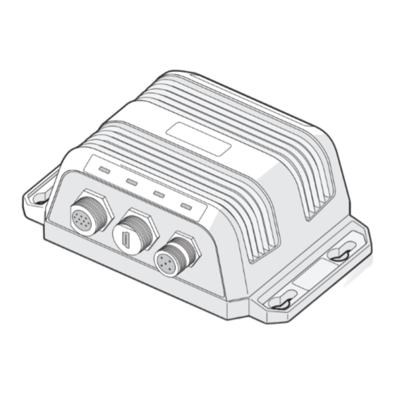
- Page 1 NAIS-400 Class B AIS Transceiver Isometric view User Manual ENGLISH www.bandg.com | www.simrad-yachting.com | www.lowrance.com...
-
Page 2: About This Manual
Please contact your nearest distributor if you require any further assistance. It is the owner’s sole responsibility to install and use the NAIS-400 AIS Class B Transceiver in a manner that will not cause accidents, personal injury or property damage. -
Page 3: Table Of Contents
Configuring your AIS transceiver Switching on your AIS transceiver for the first time Configuring your AIS transceiver Introduction to proAIS2 Operation Using the AIS transceiver Switch functions Using proAIS2 with your AIS transceiver Indicator functions Troubleshooting Specifications Contents | NAIS-400 User Manual... - Page 4 Position of the VHF antenna connector Figure 10 Connecting an external switch Figure 11 Connecting to the NMEA 0183 data port Figure 12 Connecting the power supply Figure 13 Indicator location on the AIS transceiver unit Contents | NAIS-400 User Manual...
-
Page 5: Notices
Compass safe distance The compass safe distance of this unit is 0.5 m or greater for 0.3° deviation. Notices | NAIS-400 User Manual... - Page 6 Please dispose of the packaging in an environmentally friendly manner. Accuracy of this manual The AIS transceiver may be upgraded from time to time and future versions of the AIS transceiver may therefore not correspond exactly Notices | NAIS-400 User Manual...
-
Page 7: Declaration Of Conformity
It is a violation of the rules of the Federal Communi- cations Commission to input an MMSI that has not been properly assigned to the end user, or to otherwise input any inaccurate data in this device. Notices | NAIS-400 User Manual... - Page 8 L’utilisateur de l’appareil doit accepter tout brouillage radioélectrique subi, même si le brouillage est susceptible d’en compromettre le Fonc- tionnement. Cet appareil numérique de la classe B est conforme à la norme NMB-003 du Canada. Notices | NAIS-400 User Manual...
-
Page 9: About Your Ais Class B Transceiver
A transceivers, class B transceivers, AtoNs and AIS base sta- tions but do not transmit any information about the vessel on which they are installed. • This NAIS-400 product is an AIS Class B transceiver. NAIS-400 About your AIS class B transceiver | NAIS-400 User Manual... -
Page 10: Static And Dynamic Vessel Data
In the United States of America, the MMSI and static data must only be entered by a competent installer. The end user of the equipment is not authorised to enter their own vessel data. About your AIS class B transceiver | NAIS-400 User Manual... -
Page 11: What's In The Box
Four fixing screws are provided with the product for mounting of the AIS transceiver. Please refer to the Installation procedures, chap- ter 3 for details of how to mount the AIS transceiver. 10 | About your AIS class B transceiver | NAIS-400 User Manual... -
Page 12: Figure 2 Ais Transceiver Overview
GPS antenna VHF antenna GPS antenna Mounting holes Mounting holes Mounting holes Mounting holes Power and data NMEA 2000 Power and data NMEA 200 Figure 2 AIS transceiver overview | 11 About your AIS class B transceiver | NAIS-400 User Manual... -
Page 13: Electrical Connections To The Ais Transceiver
AIS transceiver. Power in Power in NAIS-400 NAIS-400 Switch Switch NMEA 0183 NMEA0183 device device Chartplotter Chartplotter NMEA 2000 NMEA 2000 Figure 3 Electrical connections to the AIS transceiver 12 | About your AIS class B transceiver | NAIS-400 User Manual... -
Page 14: Installation
Warning: If using a VHF Antenna Splitter, you must use the NSPL-400 as it is specifically designed to work with the NAIS-400 transceiver. The use of third party antenna splitters may result in malfunction or permanent damage to the NAIS-400 transceiver. - Page 15 If you choose to use a PC or Mac with suitable charting software to display received AIS messages from other vessels, this can be accomplished by connecting to the USB connector on the AIS transceiver. 14 | Installation | NAIS-400 User Manual...
-
Page 16: Installation Procedures
The following sections explain the installation process step by step for each of the main elements of the system. Step 1 - Installing the NAIS-400 AIS transceiver Please note the following guidelines when selecting a location for your AIS transceiver: •... -
Page 17: Figure 5 Ais Transceiver Dimensions
GPS position. Also, do not mount the antenna in the direct path of a radar transmitter. To pole mount the external GPS antenna, you will require a 1-inch 14 TPI thread pole. 16 | Installation | NAIS-400 User Manual... -
Page 18: Figure 7 Gps Antenna Mounting
Remove the remaining protective film and apply the GPS antenna to the prepared mounting area with the threaded rods engaging the 4 drilled mounting holes. • Use the 4 brass washers and nuts to secure the GPS antenna. | 17 Installation | NAIS-400 User Manual... -
Page 19: Figure 8 Position Of The Gps Antenna Connector
An accessory cable is supplied with the product to provide connec- tions to power, the external switch and the NMEA 0183 data ports. The cable has a pre-moulded connector at one end which should 18 | Installation | NAIS-400 User Manual... - Page 20 RX- (Receive -) Colour-coding of wires in the accessory cable Warning: Please check your wiring very carefully before ap- plying power to the product. Failure to wire the product correctly could result in permanent damage. | 19 Installation | NAIS-400 User Manual...
-
Page 21: Figure 10 Connecting An External Switch
NMEA 0183 devices. A multiplexing feature is provided, which means any messages received via the low speed port are automatically transmitted via the high speed port and vice- versa. This is particularly useful when using a chartplotter having 20 | Installation | NAIS-400 User Manual... -
Page 22: Figure 11 Connecting To The Nmea 0183 Data Port
AIS transceiver to a PC, the USB drivers must be installed first. The USB drivers are installed as part of the proAIS2 installation pro- cess. Please install proAIS2 as described in section 4 before attempt- | 21 Installation | NAIS-400 User Manual... -
Page 23: Figure 12 Connecting The Power Supply
38,400baud Receive + Green (chart plotter) Receive – Purple Transmit + NMEA0183 Pink Transmit – Port 2 Grey 4,800baud Receive + Yellow (other NMEA0183 device) Receive – Figure 12 Connecting the power supply 22 | Installation | NAIS-400 User Manual... -
Page 24: Configuring Your Ais Transceiver
If the transceiver has not been pre-configured, the amber and red indicators will be illuminated until the configuration process has been completed. | 23 Configuring your AIS transceiver | NAIS-400 User Manual... -
Page 25: Introduction To Proais2
Insert the CD into your PC, navigate to the “proAIS2”, then the “Windows” folder and run the setup.exe file. Now follow the on-screen prompts. If a security warning appears, click ‘Install’ to continue with the installation. 24 | Configuring your AIS transceiver | NAIS-400 User Manual... -
Page 26: Configuration Using Proais2
MMSI correctly. If you need to change the MMSI for any reason, please contact your dealer who will arrange to have the MMSI reset. | 25 Configuring your AIS transceiver | NAIS-400 User Manual... -
Page 27: Operation
Indicator functions The AIS transceiver includes four coloured indicators, as shown in Figure 13. The state of the indicators provides information regarding the status of the AIS transceiver. 26 | Operation | NAIS-400 User Manual... -
Page 28: Figure 13 Indicator Location On The Ais Transceiver Unit
- the unit has been in silent mode and after deactivating silent mode this amber indicator will illuminate until the first AIS message has been sent. - the AIS transceiver has been commanded by the local authority (via an AIS base station) to cease transmissions. | 27 Operation | NAIS-400 User Manual... -
Page 29: Troubleshooting
AIS unit and/or chart- plotting software to receive AIS message 24. If the guidance given in the table above does not rectify the prob- lem you are experiencing, please contact your dealer for further assistance. 28 | Troubleshooting | NAIS-400 User Manual... -
Page 30: Specifications
9600 b/s ± 50 ppm (GMSK) 1200 b/s ± 30 ppm (FSK) RX sensitivity Less than -107 dBm at 20% PER Co-channel 10 dB Adjacent channel 70 dB IMD 65 dB Blocking 84 dB | 29 Specifications | NAIS-400 User Manual... - Page 31 FI - Finland LU - Luxembourg CH - Switzerland FR - France MT - Malta TR - Turkey DE - Germany NL - Netherlands UK - United Kingdom GR - Greece NO - Norway 30 | Specifications | NAIS-400 User Manual...
- Page 32 201-0320:2 NAIS-400 Product Manual...
Need help?
Do you have a question about the NAIS-400 and is the answer not in the manual?
Questions and answers