
Related Manuals for Monico CDL Gateway

Summary of Contents for Monico CDL Gateway
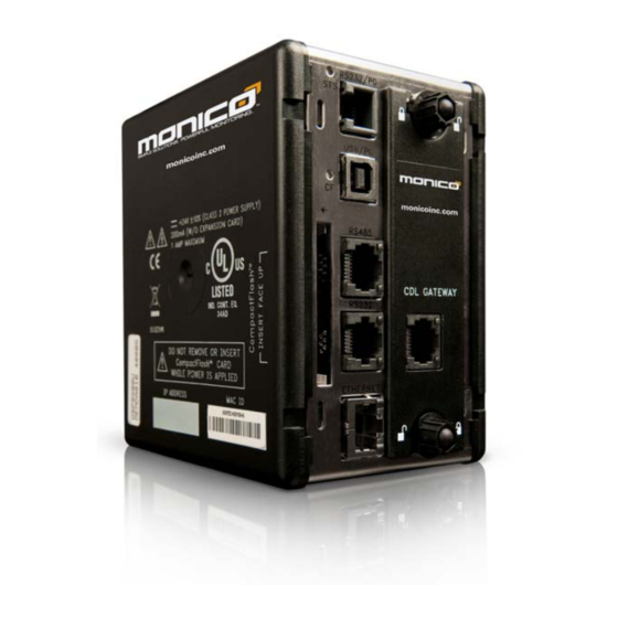
- Page 1 CDL Gateway™ Version 1.05 Installation and Operation Guide ONICO 3403 Chapel Square Spring, Texas 77388 Tel: (281) 350-8751 sales@ .com MONICOINC www. .com MONICOINC...
-
Page 2: Table Of Contents
Section 1: Power Supply ............................4 Section 2: Hardware Installation ........................... 8 Section 3: CDL Connection ............................ 9 Section 4: CDL Gateway™ Host Connections ...................... 9 Section 5: Troubleshooting LED’s ........................12 Section 6: MonicoView Programmer and User Interface ..................13 Section 7: Diagnostic and Event Codes ....................... -
Page 3: Introduction
Modbus TCP/IP over Ethernet. All ports are available on the same unit • The CDL Gateway™ has a User Interface via a USB connection that allows you to configure the ports and see exactly which parameters are responding on your installation. -
Page 4: Section 1: Power Supply
Gateway. If using an isolated power supply, make sure to use CDL Monitor 2.0. If power is applied, the green STS light will function. If this light is blinking, then no setup file is installed or it is currently loading a file. - Page 5 v1.05 6.26.09 CAUTION Reversing wire polarity may cause damage to your Gateway. This damage is not covered by warranty. If in doubt about which wire is which on your power supply, check with a meter. t is very important that the power supply is mounted If you must use an external power supply, i correctly if the unit is to operate reliably.
-
Page 6: Specifications
6.26.09 EMC INSTALLATION GUIDELINES Although the CDL Gateway™ is designed with a high degree of immunity to Electromagnetic Interference (EMI), proper installation and wiring methods must be followed to ensure compatibility in each application. The type of electrical noise, source or coupling method into a unit may be different for various installations. - Page 7 v1.05 6.26.09 CF – CompactFlash LED indicates card status and read/write activity 4. MEMORY: On-board User Memory: 4 Mbytes of non-volatile Flash memory. On-board SDRAM: DSPSX: 2 Mbytes DSPGT: 8 Mbytes Memory Card: CompactFlash Type II slot for Type I and Type II cards. 5.
-
Page 8: Section 2: Hardware Installation
v1.05 6.26.09 Section 2: Hardware Installation DIN rail should be mounted horizontally so that the unit’s ventilation holes are vertical in relation to cabinet orientation. A minimum clearance of 1 inch (25.4 mm) should be maintained above and below the unit in order to ensure proper thermal regulation Figure 2.1 Hardware Installation Figure 2.2 Hardware Dimensions... -
Page 9: Section 3: Cdl Connection
Caterpillar panel must be powered on for the data link to be active. If the Rx light is on solid, then the CDL connections are reversed or the cable length is too long. If the cable is too long, you may need to add a resistor across the terminals on the CDL Gateway™... - Page 10 v1.05 6.26.09 Host Connection-RS-232 via RJ-11 Jack Figure 4.2 RS-232 Connections Host Connections-RS-485/RS-422 via RJ-45 Jack Figure 4.3 RS-485/RS-422 Connections - 10 -...
- Page 11 v1.05 6.26.09 Figure 4.3 RS-485/RS-422 Schematic Please note that different companies use different terminology. For example, some use TxA and TxB to describe 2- wire RS-485 connections. Some use Tx+ and Tx-. In general. TxA=Tx- and TxB=Tx+ For 2-wire RS-485, use Pin#7 = (+) and Pin#8 = (-). Host Connections-TCP/IP over Ethernet via RJ-45 Shielded Jack Ethernet Figure 4.4 Ethernet Connections...
-
Page 12: Section 5: Troubleshooting Led's
Gateway is operating normally Table 5.1 STS LED SERIAL HOST PORTS - TX/RX LED’S Indication Green Transmitting Receiving Table 5.2 Serial Host Port LED’s CDL PORT - TX/RX LED’S Indication Green Transmitting Receiving Table 5.3 CDL Port LED’s TCP/IP ETHERNET PORT LED’S Indication... -
Page 13: Section 6: Monicoview Programmer And User Interface
AC supply on a laptop can cause intermittent errors with the laptop USB port. Each time you connect, using the MonicoView Software, to a new CDL Gateway unit, you will see the Windows “Found New Hardware” screen. Make sure to plug in the USB Cable when the Gateway is powered down. - Page 14 v1.05 6.26.09 Subsequent Installations When asked to go to Windows Update to find a driver, select “No, not at this time” and click “Next”. This will bring up the screen shown in Figure 6.1 below and the “Install Automatically” should be selected by default. If your first installation is not successful, you will need to follow the instructions at the end of this section to navigate to Device Manager and perform a manual install.
- Page 15 Click “Finish” when this screen is done. There is another driver that will need to be loaded, but it will not be found until you download the program to the CDL Gateway™. After the initial installation or update of the CDL Gateway™ program, Microsoft will find new hardware again and you will go through the same process again, but instead of calling it “G3...
- Page 16 RS-232 port with a multi-drop network using RS-232 to RS-485 converters. Enter the Device Address for the CDL Gateway™ (in the case of Slave protocols) in the Drop Number box and press ENTER. If the port is setup as a Master Device, then the target drop number will be entered.
- Page 17 v1.05 6.26.09 The only difference with the RS-485 port is choosing whether you want 2-wire RS-485 or 4- wire RS-485 or RS-422. This screen is shown in Figure 6.4 below. Figure 6.4: RS-485 Serial Port Settings Settings for the Ethernet port are show in Figure 6.5 and include setting the Port Mode where you set whether to Manually Configure the IP address, request an IP address from a DHCP server or use IEEE 802.3.
- Page 18 Figure 6.5: TCP/IP Ethernet Port Settings Disabling and Enabling Ports The CDL Gateway™ is a standard product that ships pre-configured with all ports active and populated with a full array of values. Since each port will have over 400 registers to update, it is recommended that you disable the unused ports by selecting the port and unchecking the box under Device Settings labeled ENABLE DEVICE as shown in Figure 6.6 below.
- Page 19 MonicoView can also be used to view live data for each data block. Highlight an individual data block and click the button labeled View Block. This will cause the software to connect to the CDL Gateway™ and display the current data for each parameter. Figure 6.7: View Data Blocks...
- Page 20 v1.05 6.26.09 A table will appear that will show the data block, the parameter tag, and the value in that register in both Decimal and Hexadecimal. Figure 6.8: Live Block Viewer Parameter Status Block A special device named “PIDStatusValues” is usually installed under the Programming RS- 232 port.
- Page 21 “PIDRawValues”. Blocks 1-4 under this Device are setup to view raw values for troubleshooting purposes. These values are the raw values read directly from the CDL Link before any gain is applied or unit conversions are performed. Note that in most of the Modbus Versions, this block is omitted because all values are raw.
-
Page 22: Section 7: Diagnostic And Event Codes
MANUAL INSTALLATION METHOD OUTLINED ABOVE. CDL MONITOR 2.0 In build 444 and above, you will have the option to choose either CDL Monitor 1.0 or CDL Monitor 2.0. CDL 2.0 is much faster than the old driver and automatically identifies more engine module configurations without need for manual intervention. - Page 23 v1.05 6.26.09 Figure 7.1 Collect Fault Data If only COLLECT FAULT DATA is checked, it will cause the following fault data to be collected: MID-Module Identifier of the diagnosing controller CID-Component Identifier of the fault device FMI or SubCode-Fault Mode Identifier showing the severity of the fault Flags-Indicates whether the codes is Event or Diagnostic Code and whether it is Active or not If FETCH FAULT DETAILS is also checked, the driver will also collect the following...
- Page 24 v1.05 6.26.09 If Bit 0 of this value is high, then the code is currently ACTIVE. If low, then it is inactive. Figure 7.2 FaultCode Data Block Figure 7.3 below shows a data block example with the Details Fault information where: FaultCount=Number of Occurrences of this specific Code FaultFirst=First Occurrence in Engine Operating Hours...
- Page 25 v1.05 6.26.09 Figure 7.3 Details Fault Code Block Example Creating Fault Blocks The pre-configured factory programs do not usually contain fault blocks because it takes up resources and is not required in the majority of applications. Creating custom Fault Blocks is easily accomplished using MonicoView Programmer using the following instructions: - 25 -...
- Page 26 v1.05 6.26.09 1. After highlighting the desired device, click on Add Gateway Block. Then highlight the Gateway Block and Click EDIT under the Starting Address section. Choose the appropriate starting address. 2. Then click EDIT under Block Size to choose the total number of registers you want to use for fault codes.
- Page 27 v1.05 6.26.09 Figure 7.5 Number of Registers to Map Screen - 27 -...
-
Page 28: Appendix A: Cdl Gateway™-Modbus Version
Modbus Master to poll the slave devices and map all the registers to the RS-232 or Ethernet port which would be setup as a Modbus Slave. The CDL Gateway™ can also mix Modbus with other protocols such as BACnet and data maps for most of the popular PLC manufacturers. -
Page 29: Modbus Register Conversion Details
A value of 1 indicates that the status is active, enabled or on. Multistate Read from modbus register as unsigned integer. The value is composed of more than one status condition. This is accomplished by setting the appropriate bits for each status condition. See details below: Monico PID Description Modbus Manual Remarks... - Page 30 Feedback, 397=Calibration Feedback, 398=No Feedback, 65504-65535 are Fault Identifiers Multistate Read from modbus register as unsigned integer. The value indicates different status conditions depending on the value being read. See details below: Monico PID Description Modbus Manual Remarks Address Generator Phase Select...
- Page 31 Multiple Status Bits Read from modbus register as unsigned integer. The value is composed of more than one status condition. This is accomplished by setting the appropriate bits for each status condition. See details below: Monico PID Description Modbus Manual Remarks...
- Page 32 6.26.09 Monico PID Description Modbus Manual Remarks Address GSC Shutdown Status 30094 Organized by bit pairs where for each pair 0=Shutdown Inactive, 1=Shutdown Active, 3=Not Available: Bits 2,1=Diag Code. Bits 4,3=Coolant Loss. Bits 6,5=Emg Stop. Bits 8,7=Spare Fault. Bits 10,9=High Coolant Temp. Bits 12,11=Low Oil Psi.
- Page 33 6.26.09 Monico PID Description Modbus Manual Remarks Address Warning Status 30239 Each of the first 24 bits represents warning status. 0 = Warning is NOT ACTIVE 1 = Warning is ACTIVE bit 1 = High exhaust temperature bit 2 = High altitude (atmospheric pressure)
- Page 34 6.26.09 Monico PID Description Modbus Manual Remarks Address bit 5 = Low engine coolant temperature bit 6 = High engine coolant temperature bit 7 = Low engine oil pressure bit 8 = High system voltage bit 9 = High engine inlet air temperature...
- Page 35 6.26.09 Monico PID Description Modbus Manual Remarks Address active; 10 = Undefined; 11 = Not available, or not installed. bits 1-2 = Underfrequency bits 3-4 = Overfrequency bits 5-6 = Undervoltage bits 7-8 = Overvoltage bits 9-10 = Generator Frequency Sensing Fault...
-
Page 36: Appendix B: Cdl Gateway™-Ccm Translator Modbus Version
RS-485 RJ-45 port, the RS-232 RJ-11 Port, or the Ethernet RJ-45 port. The purpose of these versions is to simulate the same addresses as our Monico CCM Translator, but these versions need to be specifically requested. We also offer versions that utilize other protocols such as BACnet instead of Modbus. - Page 37 A value of 1 indicates that the status is active, enabled or on. Multistate Read from Modbus register as unsigned integer. The value is composed of more than one status condition. This is accomplished by setting the appropriate bits for each status condition. See details below: Monico PID Description Modbus Manual Remarks...
- Page 38 6.26.09 Monico PID Description Modbus Manual Remarks Address Generator Phase Select 30026 0=Phase A-B Volts A current, 1=Phase B-C Volts B current, 2=Phase C-A Volts C current Generator AC Voltage Full Scale and External PT 30029 0=700v, 1=150v, 2=300, 3=500, 4=600, 5=750, 6=3k, Setpoint 7=4.5k, 8=5.25k, 9=9k, 10=15k, 11=18k, 12=30k...
- Page 39 6.26.09 Monico PID Description Modbus Manual Remarks Address Diagnostic Status Summary 30062 Bits 2-1: 0=None, 1=Level 1 Warning, 2=Level2 Warning, 3=Level 3 Warning. Bit 3&4 not used. Bit 5: 0=No logged events, 1=At least 1 logged event. Bit 6 not used. Bit7: 0=No logged diag., 1=At least 1 logged diag.
- Page 40 Read each register as an unsigned integer. Take the first value and multiply by 65536. Then add the second value. The result is composed of more than one status condition. This is accomplished by setting the appropriate bits for each status condition. See details below: Monico PID Description Modbus Manual Remarks...
- Page 41 6.26.09 Monico PID Description Modbus Manual Remarks Address bit 1 = High exhaust temperature bit 2 = High altitude (atmospheric pressure) bit 3 = Air filter plugged bit 4 = Engine overspeed bit 5 = Low engine coolant temperature...
- Page 42 6.26.09 Monico PID Description Modbus Manual Remarks Address bits 9-10 = Output 9 bits 11-12 = Undefined, future use bits 13-14 = Undefined, future use bits 15-16 = Undefined, future use bits 17-18 = Output 5 bits 19-20 = Output 6...
-
Page 43: Appendix C: Modbus Viewer Program
This section is not meant to be a user guide for the PLC, just additional information useful for use of the CDL Gateway™ with the GE Fanuc Series 90 and Versamax Modular. If you have other GE Fanuc models, please consult the factory for custom versions available. -
Page 44: Appendix E: Allen Bradley Version Notes
It is recommended that you disable this device after satisfactory installation is achieved. This will optimize the performance of the CDL Gateway™. You can always enable the device again to see them in the future. - Page 45 v1.05 6.26.09 Figure E.1: Parameter Mapping An example of the overall mapping using the other two data types is shown in E.2 below: Figure E.2: Data Mapping Example - 45 -...
-
Page 46: Appendix F: Siemens Notes
v1.05 6.26.09 SLC, MicroLogix, and PLC-5 Style Versions Since the SLC series do not support the Double Integer data type, these 32 bit integers are placed in the Floating Point registers. In most cases, the Gateway acts as a DF1 Master and pushes the engine data into the mapped data registers in the PLC, but it can read data from the PLC as well.
Need help?
Do you have a question about the CDL Gateway and is the answer not in the manual?
Questions and answers