Table of Contents
Advertisement
Quick Links
Advertisement
Table of Contents

Related Manuals for Powerwerx DB-750X

Summary of Contents for Powerwerx DB-750X
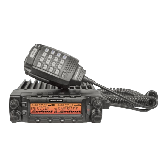
- Page 1 Powerwerx DB-750X VHF/UHF Dual Band Commercial Radio User's Manual...
- Page 2 In addition, after you READ this radio with software, first make your programming and frequency changes, then send this edited file back to your mobile radio. Please contact the dealer you purchased this radio from or Powerwerx should you have any questions.
- Page 3 The DB-750X includes 750 memory channels, 10 Do not transmit in the high power memory banks, full duplex operation, separate volume and...
-
Page 4: Table Of Contents
CONTENTS New and Innovative Features ...........1 High/Mid/Low Power Switch ..........13 Frequency Range ..............1 Frequency Reverse ...............13 Supplied Accessories/Optional Accessories ......2 Bandwidth Selection .............13 Home Channel ..............13 Supplied Accessories ..............2 Optional Accessories ..............2 Hyper Memory Channel ............13 Initial Installation ...............3 Dual Watch................14 Mobile Installation ..............3 Emergency Alarm ..............14 DC Power Cable Connection ..........4... - Page 5 TOT (Time-Out Timer) ............27 51 groups CTCSS Tone Frequency (Hz) ......37 VFO Frequency Linkage ............28 1024 groups DCS Code ............37 Wide/Narrow Band ..............28 Menu Quick Reference List ............39 Cross Band Repeat ...............28 LCD Backlight ...............28 Keypad Backlight Brightness ..........29 Calling Record ..............29 DB-750X...
-
Page 6: New And Innovative Features
Features DB-750X FEATURES: • 750 Memory Channels • 10 Memory Banks (with bank linking) • 7 Character Alphanumeric Display • Power Output: VHF 50 Watts, UHF 40 Watts (4 power levels available for each band) • Dual Receive Operation (V+U, V+V, U+U, U+V) with separate volume controls •... -
Page 7: Supplied Accessories/Optional Accessories
Connection - 6 Feet (SS-30DV) (RPS-DB750X-USB) (MBXRMK) (TMCG-72) Plain Microphone Desktop Clone Cable External Speaker Y Cable Power Line Power Adapter (MBXMIC) Microphone (MBXCLON) (MBXSPK) (MBXYCBL) Filter (LF-1-OEM) (MBXRPA) (MBXDESK) For a complete listing of current accessories see: www.powerwerx.com/mobile DB-750X... -
Page 8: Initial Installation
Initial Installation • Determine the appropriate angle of the transceiver, using the 3 MoBilE inSTAllATion screw hole positions on the side of the mounting bracket. To install the transceiver, select a safe, convenient location inside your vehicle that minimizes danger to your passengers and yourself while the vehicle is in motion. -
Page 9: Dc Power Cable Connection
If using the optional Powerwerx TMCG-72 cigarette lighter plug make sure your cigarette lighter socket in your vehicle can handle 12 VDC @ 12 Amps. - Page 10 Initial Installation B A S E STAT io n op E RATio n In order to use this transceiver for fixed base station operation, you will need an optional SS-30DV DC power supply and optional Base Station Enclosure (not included). Please contact your local Power Supply (SS-30DV) dealer for these items.
-
Page 11: Antenna Connection
Use a 50 Ω impedance antenna and low-loss coaxial feed-line that has a characteristic impedance of 50 Ω, to match the transceiver input impedance. Coupling the antenna to the transceiver via feed-lines having DB-750X... -
Page 12: Accessories Connections
Initial Installation AccESSoRiES connEcTionS Antenna (MBXGAIN) Microphone (MBXDTMF) EX TER nA l SpE Ak E R If you plan to use the optional external speaker/s (MBXSPK), there are two options. For a single speaker, plug into the upper 3.5 mm SP jack on the rear of the radio to hear both bands through one speaker. -
Page 13: Getting Acquainted
Adjust left band volume level. For channel, frequency and function display 16 LCD setup. Right Volume Knob Adjust right band volume level. Press this key and hold to adjust squelch while Squelch either turning left dial knob or right dial knob DB-750X... -
Page 14: Rear Panel
Getting Acquainted REAR pAnEl NO. INdICATOR FUNCTION ST SP ACC Displays the channel number and Menu number. Appears when current channel is priority channel. Appears when current channel is set Scan Skip. Appears when current channel has CTCSS Encode Appears when current channel has CTCSS Decode Appears when the Offset function is ON. -
Page 15: Microphone
Light green while receiving, Light red while TX/RX indicator transmitting. Speak here during transmission. Speaker Option to hear speaker thru microphone. MIC Connector Diagram (in the front view of connector) Key Pad Serial data dOWN UP / SPKR AUdIO OUT MIC GNd DB-750X... -
Page 16: Basic Operations
Press key to switch the transceiver ON, Decrease frequency Increase frequency knob clockwise to increase frequency; the LCD displays "WELCOME dB-750X", then counterclockwise to decrease frequency. Every displays current frequency or channel. click will increase or decrease frequency by one step. To adjust the Main band frequency,... -
Page 17: Switch Between Main Band And Sub Band
Transmitting is only available on the main band, the “TX” icon will display to switch the right band between 136-174MHz, 400~490MHz. in the top right corner of the main band frequency NOTE DB-750X... -
Page 18: Shortcut Operations
Shortcut Operations SqUElch lEVEl SETUp In channel mode, this operation is for temporary use only NOTE This function is used to setup the level of receiving signals. When the signal strength reaches a certain level, it will unmute the transceiver. FREqUEncY REVERSE In standby, press and hold key;... -
Page 19: Dual Watch
In channel mode, turn the selector knob to choose the channel. Hold key until the transceiver beeps and channel number MEMoRY chAnnEl ScAn Skip flashes. In channel mode, switch selector knob to choose the channel, then Turn selector knob to choose channel number for storage. (If the DB-750X... -
Page 20: Memory Channel Delete
Shortcut Operations storage has data , the LCD will display the frequency, otherwise will display"----------") Press key. The LCD will display MEN-IN, and channel copy was completed. MEMoRY chAnnEl DElETE In standby, hold key until the transceiver beeps, and channel number flashes. -
Page 21: General Setting
RX frequency ± offset frequency. The operation is as follows: Press the main band selector knob or key to store value and return to function menu. Press key or hold selector knob for one Press key to enter function menu. second to store setup and exit. DB-750X... -
Page 22: Vfo Band Lockout
General Setting cpU clock FREqUEncY chAnGE This function is auto-hidden in channel mode NOTE When any harmonic or image frequency in the CPU clock disturbs the working frequency, turn on this function to cut the image channel noise. VFo BAnD lockoUT Press key to enter function menu. -
Page 23: 5-Tone Encode Select
Turn the main band selector knob to choose No. 09 menu. The LCD code. displays "TON dEC" CTCSS: 62.5 - 254.1 Hz, and one self- Press the main band selector knob to defined group, total 52 groups enter function setup. dCS: 000N-777I, total 1024 groups DB-750X... -
Page 24: Ctcss Decode Setup
General Setting Press the main band selector knob or key to store value and SUB BAnD DiSplAY SETUp return to function menu. Press key or hold selector knob for one Press key to enter function menu. second to store setup and exit. Turn the main band selector knob to choose No. -
Page 25: Dtmf Encode Transmitting Time
DCS + optional signaling are press key back to DTMF menu. Press detected. PTT to transmit with selected DTMF code. CT/TO: Receives when any carrier or CTCSS/DCS or optional 06-16: total 16 group of DTMF code. signaling is detected. DB-750X... -
Page 26: Compander
General Setting Press the main band selector knob or key to store value and Press key to enter function menu. return to function menu. Press key or hold selector knob for one Turn the main band selector knob to second to store setup and exit. choose No. -
Page 27: Keypad Mode Setup
CTCSS/DCS scan. When a matching CTCSS/ to add/delete optional signaling, repeat the long press DCS signal is detected, the scan will pause according to to set optional signaling to DTMF, 5-Tone or 2-Tone. scan dwell time. The scan direction can be changed by DB-750X... -
Page 28: Keypad Lockout
General Setting Press the main band selector knob to enter function setup. corresponding channel selector knob. Note:To enable this function, the channel must be programmed with CTCSS/DCS Switch the main band selector knob to decode. choose desired mode. Bottom short press: The sub band will display "MAIN" BANd R, lock the right band PTT. -
Page 29: Sub Band Mute Setup
Press the main band selector knob to enter function setup. return to function menu. Press key or hold selector knob for one Switch the main band selector knob to second to store setup and exit. choose desired value. DB-750X... -
Page 30: Microphone Pa, Pb, Pc, Pd Key Setup
General Setting MANUAL: Auto storage is turned off. S-5: Able to hear a signal when the level meter reaches 4 bars. S-9: Able to hear a signal when the level meter reaches 8 bars. AUTO: Auto storage is turned on. S-FULL: Able to hear a signal when the level meter reaches full bars. -
Page 31: Priority Channel Scan
Before using the priority channel scan function, the edited channel must be NOTE return to function menu. Press key or hold selector knob for 1 programmed as "P SCAN". second to store setup and exit. DB-750X... -
Page 32: Busy Channel Lockout
General Setting 5 TonE SElF iD EnqUiRY BUSY chAnnEl lockoUT With this function on, the transceiver will not transmit on a busy Press key to enter function menu. channel, to avoid disturbing other transceivers using same frequency. Switch the selector knob to choose No. 40 If the channel is busy and you press PTT, the transceiver will beep as function. -
Page 33: Vfo Frequency Linkage
Press key or hold selector menu. Press key or hold selector knob for one second to store setup and knob for one second to store setup and exit. Refer to Wide/Narrow exit. table in appendix. DB-750X... -
Page 34: Keypad Backlight Brightness
General Setting MicRophonE kEYpAD BAckliGhT BRiGhTnESS choose desired value. Press key to enter function menu. ON: turn on AM function. OFF: turn off AM function. Turn the main band selector knob to Press the main band selector knob or key to store value and choose No. -
Page 35: Beep Volume Control
When password function is on, you will be required to enter it after power Switch the main band selector knob to choose desired value on. The password must be programmed before using this function. ON: Turn on Talk Around OFF: Turn off Talk Around NOTE DB-750X... -
Page 36: Microphone Operation
Microphone Operation DOWN This function is valid only when current channel is set with offset frequency. NOTE Main/Sub band switch PRI: Add or delete priority channel. In channel mode, press the key programmed as PRI function to set priority channel. When the LCD displays Numeric Keys current channel is set as priority channel. - Page 37 TBST: Transmit tone burst. In standby, OFF: No function. press the key programmed as "TBST" function to transmit selected tone burst. This function is used to access some repeaters. DB-750X...
-
Page 38: Memory Banks
10 memory banks are available for memory channel assignments to BAnk linkinG ease in operation of the DB-750X dual band radio. You can enable one Memory banks can be linked together for expanded scanning or viewing. bank or multible banks through either software programming or through Press key to enter function menu. -
Page 39: Cable Clone
If your radio seems to be malfunctioning because of wrong operation or setup, this function will be able to resume all setup and channels to factory default. Hold the top button while powering on the radio. All channel and function setups will resume to factory default. All memory channels will be erased. DB-750X... -
Page 40: Maintenance
Maintenance DEFAUlT VAlUE FoR FAcToRY RESUME TRoUBlE ShooTinG Dual Band Mobile Radio Possible Causes and Potential Solutions Problem Left band Right band + and - polarities of power connection are (a) Power is on, nothing reversed. Connect red lead to plus terminal VFO frequency 145.150 MHz 435.150 MHz... -
Page 41: Specifications
Frequency stability ±2.5 ppm Spurious emission ≥70 dB ≥70 dB Audio response +1~-3dB (0.3-3 kHz) +1~-3dB (0.3-2.55 kHz) Operating temperature -20 ~ +60°C Audio distortion ≤5% Dimensions(WxHxD) 139 (W) x 40 (H) x 212 (D) mm Weight about 1.14 kg DB-750X... -
Page 42: Attached Chart
Attached Chart 1024 GRoUpS DcS coDE 51 GRoUpS cTcSS TonE FREqUEncY(hz) 62.5 77.0 91.5 107.2 127.3 151.4 167.9 183.5 199.5 225.7 254.1 Self 67.0 79.7 94.8 110.9 131.8 156.7 171.3 186.2 203.5 229.1 Defined 69.3 82.5 97.4 114.8 136.5 159.8 173.8 189.9 206.5 233.6 71.9 85.4 100.0 118.8 141.3 162.2 177.3 192.8 210.7 241.8 74.4... - Page 43 Attached Chart DB-750X...
-
Page 44: Menu Quick Reference List
Menu Quick Reference List Menu Name default Page Function Settings APO (AUTOMATIC POWER OFF) Settings from 0.5 through 12 hours, OFF AUTOMATIC OFFSET OFF; when ON, offset for 136-174 MHz is 0.6 MHz; 400-490 MHz is 5 MHz STEP FREQUENCY CHANNEL STEP SETUP (in Hz) 2.5 k, 5 k, 6.25 k,10 k,12.5 k,15 k, 20 k, 25 k, 30 k, 50 k BAND VFO BAND LOCKOUT... - Page 45 ENABLE LINK TO THE MAIN BANK SET ON/OFF BLK H OFF* ENABLE LINK TO THE MAIN BANK SET ON/OFF BLK I OFF* ENABLE LINK TO THE MAIN BANK SET ON/OFF BLK J OFF* ENABLE LINK TO THE MAIN BANK SET ON/OFF PASS Enter a PASSWORD DB-750X...
- Page 46 Powerwerx 263 N Berry St Brea, CA 92821 www.powerwerx.com Rev D 8/2013...
Need help?
Do you have a question about the DB-750X and is the answer not in the manual?
Questions and answers
is it possible to connect a helmet headset to RJ45 connector on the DB-750 ?