Table of Contents
Advertisement
Advertisement
Table of Contents

Related Manuals for ALLEN & HEATH Xone: S2


Summary of Contents for ALLEN & HEATH Xone: S2
-
Page 1: User Guide
USER GUIDE Publication AP6858_3 Allen & Heath XONE:S2 User Guide... -
Page 2: Warranty
Limited One Year Warranty This product is warranted to be free from defects in materials or workmanship for period of one year from the date of purchase by the original owner. To ensure a high level of performance and reliability for which this equipment has been designed and manufactured, read this User Guide before operating. -
Page 3: Packed Items
PACKED ITEMS Check that you have received the following: TO PC Xone:S2mixer S h o r t i n g Jumper Type A-B USB Lead To connect the Xone:S2 to your computer. Mains Lead Check that the correct mains plug is fitted. 90 degree 3.5mm jack adapter Spare knobs... -
Page 4: Table Of Contents
CONTENTS Congratulations on purchasing the Allen & Heath Xone:S2 performance DJ mixer. To ensure that you get the maximum benefit from the unit please spare a few minutes familiarizing yourself with the controls and setup procedures outlined in this user guide. For further information please refer to the additional information available on our web site, or contact our technical support team. -
Page 5: Panel Drawings
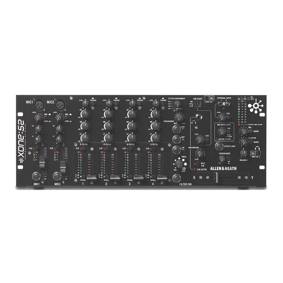
MADE IN THE UK BY ALLEN & HEATH LIMITED Front Panel TO PC Fader Plates The Xone: S2 can be ordered with either rotary or linear faders. The plates are interchangeable and can be ordered separately. Linear Fader Plate— Xone:S2-Linear Rotary Fader Plate—... -
Page 6: Introduction
INTRODUCTION TO THE XONE:S2 The Xone:S2 is a 19” rack mounted 4U analogue DJ mixer featuring four stereo dual input channels, two Mono Mic/Stereo Line channels, and is available with either 45mm linear, or rotary VCA faders. This mixer is designed for use in clubs, wine bars, and professional mobile DJ road shows, and incorpo- rates many features to aid the installer, protect the sound system from overload, and enhance the DJs performance. -
Page 7: Specifications
SPECIFICATIONS Operating Levels Input RIAA input sensitivity 7-100mV 47K/330pF Line Inputs -10dB to +15dB RCA Mic Sensitivity -57 to –27dBu Balanced XLR USB Audio In 0dBu RCA Alarm Input 0dBu Phoenix connector Mix Insert Return -2dBu RCA Channel Insert Return 0dBu 1/4”... -
Page 8: Block Diagram
BLOCK DIAGRAM FILTER MIX EXTERNAL DC XONE:S2 ROTARY 2= + OPTION BLOCK DIAGRAM ZONE + 4dBu FILTER PRE MASTER FILTER EXTERNAL ASSIGNMENT 2= + INPUT LEVEL CH 4 CH 3 CH 2 SELECT DC FADER CH 1 EXTERNAL RESONANCE REMOTE 0- 10 VOLTS EXT LEVEL CONTROL FADER START CCT AUDIO LIGHT FEED... -
Page 9: Mic / Line Channel Input
MIC / LINE INPUT CHANNEL Mic Input Socket Standard 3-Pin XLR socket wired as Pin 1 = Ground, Pin 2 = hot (+), Pin 3 = cold (-). Mic / Line Select Switch Selects either the XLR microphone input or the alterna- tive RCA stereo line input. - Page 10 MIC / LINE INPUT CHANNEL Channel Meter Displays the channel signal level. It is post EQ and pre- fader. This means it is not affected by the fader position. The channel level control should be set so that the me- ter averages around ‘0’...
-
Page 11: Phono / Line Input Channel
PHONO / LINE INPUT CHANNEL Phono / Line Select Switch Selects either the RCA phono input or the alternative RCA stereo line input. In the up position PHONO is selected, when pressed LINE is selected. Channel Level Control This control has a range of –10 to +4dB dependant upon the channel trim. - Page 12 PHONO / LINE INPUT CHANNEL Channel Meter Displays the channel signal level. It is pre-EQ and pre- fader, allowing the input level to be displayed even if the EQ is set to off on all bands. To view the post EQ level, press the cue switch and use the mix/monitor meters.
-
Page 13: Filters Section
FILTER SECTION Filter Assign Selector Selects the channel to be routed through the filter. The FILTER LED in the selected channel section will light when selected. The EXTERNAL LED will light when the selector is set to EXTERNAL. NOTE: To prevent accidental assignment of the filter there is a delay when selecting an individual channel. -
Page 14: Filter Section
FILTER SECTION Frequency Sweep Control This control sets the –3dB cut-off frequency of the filter. It ranges from very low frequency (20Hz) to very high frequency (20kHz). NOTE: Both BPF and HPF filters are band limited to prevent them going above 10kHz. Filter On Switch Switches the filter on and off. -
Page 15: Usb / Headphone Section
USB / HEADPHONE SECTION USB Connector USB (Universal Serial Bus) V1.1 is an external peripheral interface standard for data transmission. Xone:S2 USB works at 12Mbps and provides two stereo uncom- TO PC pressed audio channels. It is fully compatible with USB2. The USB connection is used to send and receive audio data between the Xone:S2 and a connected computer. - Page 16 USB / HEADPHONE SECTION Headphone Level Control Adjusts the level of the headphone signal. TO PC Warning ! To avoid damage to your hearing do not operate the headphones or sound system at excessively high volume. Continued exposure to high volume sound can cause frequency selective or wide range hearing loss.
-
Page 17: Headphone Cable Clips
HEADPHONE CABLE CLIPS Wire Clips Two wire clips are provided for the purpose of securing the headphone cabling away from the front panel controls of the mixer. NOTE: A third headphone socket is available on the rear of the mixer. This connection may be used for mounting a headphone extension lead into a blank 19”... -
Page 18: External Input/Autoduck/Fx Loop
EXTERNAL INPUT / AUTO DUCK / EFFECT LOOP External Input Sockets Front-panel mounted stereo RCA sockets for easy con- nection of external line level audio sources. External Input Level Control The external input level control ranges from -∞ to +6dB based on the input level. - Page 19 EXTERNAL INPUT / AUTO DUCK / EFFECT LOOP Ducker Active LED Lights when the main outputs are being ducked. Also lights when the external alarm input switch closure is active. Effect Loop Switch Switches in the FX insert circuit. The LED indicator around the switch lights when selected.
-
Page 20: Master Section
MASTER SECTION Mix / Monitor Meters The main meters follow the selected monitor source. The default display is the post master level, which is overridden with an input channel level if the channel cue switch is selected. In split cue mode, the left master meter will display the cued channel signal level and the right master meter will display the mix level. - Page 21 MASTER SECTION Monitor Mono Switch Sums the left and right signal levels to produce a mono mix from both outputs. Balance Control Use to compensate for poor signal balance between left and right or as a panning effect. The balance control is disabled if the outputs are set to mono.
-
Page 22: Crossfader
CROSSFADER Crossfader Curve Control This control adjusts the crossfader curve between dipped response, ideal for seamless beat mixing, and fast-attack, suitable for scratch or cut mixing . Crossfader On Switch In its normal (out) position the crossfader is active. Push the switch to turn the crossfader off—the channel LED indication will also be switched off. -
Page 23: Rear Connectors
REAR CONNECTORS + OUT DO NOT SHORT PIN 3 TO GROUND -OUT FOR UNBALANCED OPERATION MIC INPUT MIX OUT MONO CONNECT TO PIN 2 ONLY + IN FADER START 4 FADER START 3 FADER START 2 FADER START 1 - IN LEFT + 4dBu + 4dB u... - Page 24 REAR CONNECTORS + OUT DO NOT SHORT PIN 3 TO GROUND -OUT FOR UNBALANCED OPERATION MIC INPUT MIX OUT MONO CONNECT TO PIN 2 ONLY + IN FADER START 4 FADER START 3 FADER START 2 FADER START 1 - IN LEFT + 4dBu + 4dB u...
-
Page 25: Monitor Output
REAR CONNECTORS + OUT DO NOT SHORT PIN 3 TO GROUND -OUT FOR UNBALANCED OPERATION MIC INPUT MIX OUT MONO CONNECT TO PIN 2 ONLY + IN FADER START 4 FADER START 3 FADER START 2 FADER START 1 - IN LEFT + 4dBu + 4dB u... - Page 26 REAR CONNECTORS + OUT + OUT DO NOT SHORT PIN 3 TO GROUND DO NOT SHORT PIN 3 TO GROUND -OUT -OUT FOR UNBALANCED OPERATION FOR UNBALANCED OPERATION MIC INPUT MIC INPUT MIX OUT MIX OUT MONO MONO CONNECT TO PIN 2 ONLY CONNECT TO PIN 2 ONLY + IN + IN...
- Page 27 REAR CONNECTORS + OUT DO NOT SHORT PIN 3 TO GROUND -OUT FOR UNBALANCED OPERATION MIC INPUT MIX OUT MONO CONNECT TO PIN 2 ONLY + IN FADER START 4 FADER START 3 FADER START 2 FADER START 1 - IN LEFT + 4dBu + 4dB u...
-
Page 28: Rear Connectors-Zone Out
REAR CONNECTORS - ZONE OUT 22 23 PRE MASTER LEVEL EXT LEVEL CTRL ALARM INPUT LEFT ZONE OUT ALARM TIP + + 4dBu ALARM N/O RING - RING ALARM AUDIO DO NOT SHORT RING TO GROUND FOR UNBALANCED OPERATION RIGHT + 10V EXT CONNECT TO TIP ONLY LEVEL 0 -10V... - Page 29 REAR CONNECTORS - ZONE OUT PRE MASTER LEVEL EXT LEVEL CTRL ALARM INPUT LEFT ZONE OUT ALARM TIP + + 4dBu ALARM N/O RING - RING ALARM AUDIO DO NOT SHORT RING TO GROUND FOR UNBALANCED OPERATION RIGHT + 10V EXT CONNECT TO TIP ONLY LEVEL 0 -10V 5KRD...
-
Page 30: User Link Options
USER LINK OPTIONS CAUTION: The following service instructions are for use by qualified personnel only. To reduce the risk of electric shock do not perform any servicing other than that described in the operating instructions unless you are qualified to do so. Refer all servicing to qualified service personnel. - Page 31 USER LINK OPTIONS Filter PCB Remove JP1to disable the Filter On switch. Headphone PCB To change the USB Audio input feed from the RCA sockets on the rear panel (default) to the internal left/right mix buss, move jumper links CN8 and CN9 from pins 2-3 to 1-2.
-
Page 32: Replacing Crossfader / Fader Plate
REPLACING THE CROSSFADER / FACE PLATE Replacing the Crossfader Use a medium size cross-point screwdriver to undo and remove the two outer screws on the crossfader plate. Do not remove the inner screws. Carefully pull the crossfader assembly away from the front panel. Unplug the cable from the old crossfader and plug in the new assembly. Check that the connector is correctly aligned and pushed on.
Need help?
Do you have a question about the Xone: S2 and is the answer not in the manual?
Questions and answers