
Related Manuals for Comtrend Corporation NexusLink 5631


Summary of Contents for Comtrend Corporation NexusLink 5631
-
Page 1: User Manual
NexusLink 5631 Wireless ADSL2+ Bonded Router User Manual Version C1.3, February 19, 2008 261076-005... - Page 2 Copyright Copyright© 2007 Comtrend Corporation. All rights reserved. The information contained herein is proprietary to Comtrend Corporation. No part of this document may be translated, transcribed, reproduced, in any form, or by any means without the prior written consent of Comtrend Corporation.
-
Page 3: Table Of Contents
Table of Contents CHAPTER 1 INTRODUCTION ....................5 1.1 F ............................5 EATURES 1.2 A ...........................6 PPLICATION 1.3 F LED I ......................7 RONT ANEL NDICATORS CHAPTER 2 INSTALLATION ......................8 2.1 H ......................8 ARDWARE NSTALLATION 2.2 USB D ..................10 RIVER UTORUN NSTALLATION 2.3 USB D OS) ................13 RIVER ANUAL... - Page 4 6.3.2 Port Triggering .......................58 6.3.3 DMZ Host ........................59 6.3.4 ALG..........................60 6.4 S ............................61 ECURITY 6.4.1 MAC Filtering.........................61 6.4.2 IP Filtering ........................63 6.4.3 Parental Control ......................66 6.5 Q ........................67 UALITY OF ERVICE 6.5.1 Queue Management Configuration ................67 6.5.2 QoS Queue Configuration ....................67 6.6 R ............................70 OUTING...
- Page 5 9.2 S ..........................104 YSTEM 9.3 SNMP A ..........................106 GENT 9.4 TR-069 C ...........................107 LIENT 9.5 I ...........................108 NTERNET 9.6 A ........................109 CCESS ONTROL 9.6.1 Services.........................109 9.6.2 IP Addresses ......................... 110 9.6.3 Passwords ........................111 9.7 U ........................112 PDATE OFTWARE 9.8 S ........................
-
Page 6: Chapter 1 Introduction
802.11g wireless LAN access point. It has robust routing capabilities to segment and direct data streams and allows for multiple data encapsulations. The NexusLink 5631 is a black box solution for deploying Triple Play architectures, doubling bandwidth (48Mbps) performance over traditional ADSL2+ modems. It provides higher level performance with embedded security, QoS, VPN and remote management functions. -
Page 7: Application
1.2 Application This diagram depicts the application of the NexusLink 5631 on a wireless network. -
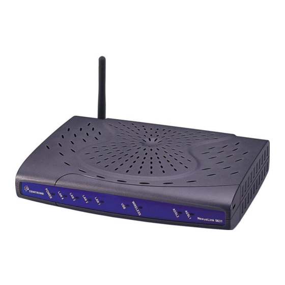
Page 8: Front Panel Led Indicators
1.3 Front Panel LED Indicators The front panel LED indicators are pictured below with detailed explanation provided in the table underneath. Color Mode Function POWER Green The router is powered up. The router is powered down. Green An Ethernet Link is established. An Ethernet Link is not established. -
Page 9: Chapter 2 Installation
Chapter 2 Installation 2.1 Hardware Installation Follow the instructions below to complete the hardware installation. A diagram of the back panel of the router is shown below for reference. Power button Host Reset button Connection to Power Connect the power jack to the shipped power cord. Attach the power adapter to the wall outlet or other AC source. - Page 10 Connection to USB host port This device is equipped with one high-speed USB 2.0 host connection. With software support, users can connect USB devices such as printers and a hard disc to the router. For this software release, printer service is supported. Connection to LAN port To connect to a hub or PC, use a RJ45 cable.
-
Page 11: Usb Driver Autorun Installation
2.2 USB Driver Autorun Installation Before connecting the NexusLink 5631 to a PC with USB, the correct drivers must be installed. The auto-run USB driver installation supports Win ME, Win 98, Win 2000, Win XP (32 bit) and Vista (32 bit). For those using Windows XP 64 bit, the driver must be installed manually (please see section 2.3 below for details). - Page 12 STEP 2: The following window will be displayed. Click the Next button to continue. STEP 3: When the window displays as below, wait for the drivers to fully install.
- Page 13 STEP 4: Click the Finish button, when the window displays as below. STEP 5: The installation is complete. You can now connect the device to your PC using a standard USB cable.
-
Page 14: Usb Driver Manual Installation (64Bit Os)
2.3 USB Driver Manual Installation (64bit OS) Before connecting this router to a PC with USB, the correct drivers must be installed. Follow the procedure below to manually install the 64bit USB driver STEP 1: Connect the USB port to the PC by plugging the flat connector of a standard USB cable into your PC and plugging the square connector into the device. - Page 15 STEP 2: When the window displays as below, select Install from a list or specific location (Advanced) and then click the Next button. Note: This window won’t display if the USB Driver has been previously installed. In this case, contact technical support for assistance. STEP 3: Insert the installation CD.
- Page 16 STEP 4: Select the location of the file using the Browse button, as shown above. Normally, the file is on the CD-ROM shipped with the device. STEP 5: Locate the Vista folder, and click OK.
- Page 17 STEP 6: When the window displays as below, click the NEXT button and wait.
- Page 18 STEP 7: Click the Finish button when the window displays as below. STEP 8: Installation is complete.
-
Page 19: Chapter 3 Web User Interface
Chapter 3 Web User Interface This section describes how to manage the router via a web browser. The web page is best viewed with Microsoft Internet Explorer 5.0 and later. A unique default user account is assigned with user name root and password 12345. The user can change the default password later when logged in to the device. -
Page 20: Login Procedure
3.2 Login Procedure Perform the following steps to bring up the web browser and configure the router. STEP 1: Start the Internet browser. Type the IP address for the router in the Web address field. For example, if the IP address is 192.168.1.1, type http://192.168.1.1 STEP 2: You will be prompted to enter your user name and password. -
Page 21: Default Settings
3.3 Default Settings During power on initialization, the router sets all configuration attributes to default values. It will then read the configuration profile from flash memory. The default attributes are overwritten when identical attributes with different values are configured. The configuration profile can be created via the web browser, telnet user interface or other management protocols. -
Page 22: Chapter 4 Quick Setup
The selections available on the main menu are based upon the configured connection type and user account privileges. The Quick Setup screen allows the user to configure the NexusLink 5631 for ADSL connectivity and Internet access. It also guides the user though the WAN network setup first and then the LAN interface setup. - Page 23 The following configuration considerations apply: • The WAN network operating mode operation depends on the service provider’s configuration in the Central Office and Broadband Access Server for the PVC • If the service provider provides PPPoE service, then the connection selection depends on whether the LAN-side device (typically a PC) is running a PPPoE client or whether the router is to run the PPPoE client.
-
Page 24: Auto Quick Setup
4.1 Auto Quick Setup The auto quick setup requires the ADSL link to be up. The ADSL router will automatically detect the PVC, so just follow the easy online instructions. STEP 1: Select Quick Setup to display this screen. STEP 2: Click Next to start the setup process. Follow the online instructions to complete the settings. -
Page 25: Manual Quick Setup
4.2 Manual Quick Setup STEP 1: Click Quick Setup and un-tick the DSL Auto-connect checkbox to enable manual configuration of the connection type. Untick this checkbox to enable manual setup and display the following screen. STEP 2: Enter the PORT, Virtual Path Identifier (VPI) and Virtual Channel Identifier (VCI) values. - Page 26 STEP 3: Choose an Encapsulation mode. Choosing different connection types provides different encapsulation modes. • PPPoA- VC/MUX, LLC/ENCAPSULATION • PPPoE- LLC/SNAP BRIDGING, VC/MUX • MER- LLC/SNAP-BRIDGING, VC/MUX • IPoA- LLC/SNAP-ROUTING, VC MUX • Bridging- LLC/SNAP-BRIDGING, VC/MUX NOTE: Subsections 4.2.1 - 4.2.4 describe the PVC setup procedure further. Choosing different connection types pops up different settings requests.
-
Page 27: Ppp Over Atm (Pppoa) And Ppp Over Ethernet (Pppoe)
4.2.1 PPP over ATM (PPPoA) and PPP over Ethernet (PPPoE) STEP 4: Select the PPP over ATM (PPPoA) or PPP over Ethernet (PPPoE) radio button and click Next. The following screen appears. Enable Fullcone NAT Known as one-to-one NAT, all requests from the same internal IP address and port are mapped to the same external IP address and port. - Page 28 Disconnect if no activity The router can be configured to disconnect if there is no activity for a period of time by selecting the Dial on demand check box. When the checkbox is ticked, you need to enter the inactivity timeout period. The timeout period ranges from 1 minute to 4320 minutes.
- Page 29 STEP 5: Click Next to display the following screen. Enable IGMP Multicast checkbox: Tick the checkbox to enable IGMP multicast (proxy). IGMP (Internet Group Membership Protocol) is a protocol used by IP hosts to report their multicast group memberships to any immediately neighboring multicast routers. Enable WAN Service checkbox: Tick this item to enable the ATM service.
- Page 30 STEP 6: After entering your settings, select Next. The following screen appears. This screen allows the user to configure the LAN interface IP address, subnet mask and DHCP server. To assign dynamic IP address, DNS server and default gateway to other LAN devices, select the button Enable DHCP server on the LAN and enter the start and end IP addresses and DHCP leased time.
- Page 31 STEP 7: Click Next to continue. To enable the wireless function, select the radio button (as shown), input a new SSID (if desired) and click Next. STEP 8: Click Next to display the WAN Setup-Summary screen that presents the entire configuration summary. Click Save/Reboot if the settings are correct.
-
Page 32: Mac Encapsulation Routing (Mer)
4.2.2 MAC Encapsulation Routing (MER) Step 4: Select the MAC Encapsulation Routing (MER) radio button and click Next. Enter information provided to you by your ISP to configure the WAN IP settings. NOTE: DHCP can be enabled for PVC in MER mode if Obtain an IP address automatically is chosen. - Page 33 Step 5: Click Next to display the following screen. Enable NAT checkbox: If the LAN is configured with a private IP address, the user should select this checkbox. The NAT submenu on the left side main panel will be displayed after reboot. The user can then configure NAT-related features after the system comes up.
- Page 34 Enable IGMP Multicast: Tick the checkbox to enable IGMP multicast (proxy). IGMP (Internet Group Membership Protocol) is a protocol used by IP hosts to report their multicast group memberships to any immediately neighboring multicast routers. Enable WAN Service: Tick the checkbox to enable the WAN service. If this item is not selected, you will not be able to use the WAN service.
- Page 35 This screen allows the user to configure the LAN interface IP address, subnet mask and DHCP server. To assign dynamic IP address, DNS server and default gateway to other LAN devices, select Enable DHCP server and enter the start and end IP addresses and DHCP leased time.
- Page 36 Step 8: After clicking Save/Reboot, the router will save the configuration to flash memory and reboot. After the device reboots, the Web UI will refresh to the Device Info screen. The router is ready for operation when the LED indicators display correctly, as described in section 1.3.
-
Page 37: Ip Over Atm
4.2.3 IP Over ATM Step 4: Select the IP over ATM (IPoA) radio button and click Next. NOTE: DHCP is not supported over IPoA. The user must enter the IP address or WAN interface for the default gateway setup and the DNS server addresses provided by their ISP. - Page 38 Enable Fullcone NAT: This option becomes available when NAT is enabled. Known as one-to-one NAT, all requests from the same internal IP address and port are mapped to the same external IP address and port. An external host can send a packet to the internal host, by sending a packet to the mapped external address.
- Page 39 Step 6: Click Next to display the following screen. This screen allows the user to configure the LAN interface IP address, subnet mask and DHCP server. To assign dynamic IP address, DNS server and default gateway to other LAN devices, select the button Enable DHCP server on the LAN and enter the start and end IP addresses and DHCP leased time.
- Page 40 STEP 7: Click Next to continue. To enable the wireless function, select the radio button (as shown) and input a new SSID (if desired). Click Next to continue. Step 8: After clicking Save/Reboot, the router will save the configuration to flash memory and reboot.
-
Page 41: Bridging
4.2.4 Bridging Step 4: Select the Bridging radio button and click Next. The following screen appears. To use the bridge service, tick the checkbox, Enable Bridge Service, and enter the service name. Step 5: Click the Next button to continue. Enter the IP address for the LAN interface. - Page 42 STEP 6: Click Next to continue. To enable the wireless function, select the radio button (as shown), input a new SSID (if desired) and click Next. The following screen will be displayed. Step 7: After clicking Save/Reboot, the router will save the configuration to flash memory and reboot.
-
Page 43: Chapter 5 Device Info
Chapter 5 Device Info Select Device Info from the main menu to display Summary information as below. NOTE: The screen above gives a DSL status summary for ADSL1. For the status of ADSL2 consult the next selection on the menu: Slave Info. - Page 44 Version The software version for the second CPU. Status The status of the second CPU. Channel Channel type Interleave or Fast for the second CPU. ADSL supports two modes of transport called the fast channel and interleaved channel. The fast channel is meant to transfer latency-critical but error tolerant data streams like real time video.
-
Page 45: Wan
5.1 WAN Select WAN from the Device Info menu to display the status of all configured PVC(s). Port/VPI/VCI Shows the values of the ATM Port/VPI/VCI VLAN Mux Shows 802.1Q VLAN ID Con. ID Shows the connection ID Category Shows the ATM service classes Service Shows the name for WAN connection Interface... -
Page 46: Statistics
5.2 Statistics Selection of the Statistics option provides statistics for the Network Interface of LAN, WAN, ATM and ADSL. These statistics screens are updated every 15 seconds. 5.2.1 LAN Statistics The Network Statistics screen shows interface statistics for Ethernet and Wireless interfaces. -
Page 47: Wan Statistics
5.2.2 WAN Statistics Service Shows the service type VPI/VCI Shows the values of the ATM VPI/VCI Protocol Shows the connection type, such as PPPoE, PPPoA, etc. Interface Shows connection interfaces Received/Transmitted - Bytes Rx/TX (receive/transmit) packets in bytes - Pkts Rx/TX (receive/transmit) packets - Errs Rx/TX (receive/transmit) packets with errors... -
Page 48: Atm Statistics
5.2.3 ATM statistics ATM Interface Statistics Field Description In Octets Number of received octets over the interface Out Octets Number of transmitted octets over the interface In Errors Number of cells dropped due to uncorrectable HEC errors In Unknown Number of received cells discarded during cell header validation, including cells with unrecognized VPI/VCI values, and cells with invalid cell header patterns. - Page 49 In Oam RM CRC Number of OAM and RM cells received with CRC errors Errors In GFC Errors Number of cells received with a non-zero GFC. ATM AAL5 Layer Statistics over ADSL interface Field Description In Octets Number of received AAL5/AAL0 CPCS PDU octets Out Octets Number of received AAL5/AAL0 CPCS PDUs octets transmitted In Ucst Pkts...
-
Page 50: Adsl Statistics
5.2.4 ADSL Statistics The following graphic shows the ADSL Network Statistics screen. Within the ADSL Statistics window, a Bit Error Rate (BER) test can be done using the ADSL BER Test button. The Reset Statistics button refreshes the statistics. NOTE: This screen displays information for ADSL1. - Page 51 Field Description Mode Line Coding format Type Channel type: Interleave or Fast Line Coding Trellis On/Off Status Lists the status of the ADSL link Link Power State Link output power state. SNR Margin (dB) Signal to Noise Ratio (SNR) margin Attenuation (dB) Estimate of average loop attenuation in the downstream direction.
-
Page 52: Route
5.3 Route 5.4 ARP... -
Page 53: Dhcp
5.5 DHCP... -
Page 54: Chapter 6 Advanced Setup
Chapter 6 Advanced Setup This chapter explains: WAN, LAN, NAT, Security, QoS, Routing, DNS, DSL …… NOTE: Shown below are the menu options for each connection type. This screenshot is for PPPoE and PPPoA encapsulations. This screenshot is for MER and IPoA encapsulations. -
Page 55: Wan
This screenshot shows MAC Filtering which is available only with Bridge connections. 6.1 WAN Port/VPI/VCI ATM Port (0-3) / VPI (0-255) / VCI (32-65535) VLAN Mux Shows 802.1Q VLAN ID Con. ID ID for WAN connection Category ATM service category, e.g. UBR, CBR… Service Name of the WAN connection Interface... -
Page 56: Lan
6.2 LAN Configure the ADSL Router IP Address and Subnet Mask for LAN interface. Save button only saves the LAN configuration data. Save/Reboot button saves the LAN configuration data and reboots the device to make the new configuration effective. (Slave) IP Address: Enter the IP address for the LAN port. (Slave) Subnet Mask: Enter the subnet mask for the LAN port. -
Page 57: Nat
6.3 NAT To display the NAT function, the NAT option must be enabled in WAN Setup. 6.3.1 Virtual Servers Virtual Server allows you to direct incoming traffic from WAN side (identified by Protocol and External port) to the Internal server with private IP address on the LAN side. - Page 58 Select a Service User should select the service from the list. Custom Server User can enter the name of their choice. Server IP Address Enter the IP address for the server. External Port Start Enter the starting external port number (when you select Custom Server).
-
Page 59: Port Triggering
6.3.2 Port Triggering Some applications require that specific ports in the router’s firewall be opened for access by the remote parties. Port Trigger dynamically opens up the ‘Open Ports’ in the firewall when an application on the LAN initiates a TCP/UDP connection to a remote party using the ‘Triggering Ports’. -
Page 60: Dmz Host
Select an Application User should select the application from the list. Or Custom Application Or User can enter the name of their choice. Trigger Port Start Enter the starting trigger port number (when you select custom application). When an application is selected the port ranges are automatically configured. -
Page 61: Alg
6.3.4 SIP ALG is Application layer gateway. If the user has an IP phone (SIP) or VoIP gateway (SIP) behind the ADSL router, the SIP ALG can help VoIP packet passthrough the router (NAT enabled). NOTE: SIP (Session Initiation Protocol, RFC3261) is the protocol of choice for most VoIP (Voice over IP) phones to initiate communication. -
Page 62: Security
6.4 Security To display the Security function, the firewall option must be enabled in WAN Setup. 6.4.1 MAC Filtering Each network device has a unique MAC address. You can block or forward the packets based on the MAC addresses. The MAC Filtering Setup screen allows for the setup of the MAC filtering policy and rules. - Page 63 Field Description Protocol type PPPoE, IPv4, IPv6, AppleTalk, IPX, NetBEUI, IGMP Destination MAC Address Defines the destination MAC address Source MAC Address Defines the source MAC address Frame Direction Select the incoming/outgoing packet interface...
-
Page 64: Ip Filtering
6.4.2 IP Filtering IP filtering allows you to create a filter rule to identify outgoing/incoming IP traffic by specifying a new filter name and at least one condition below. All of the specified conditions in this filter rule must be satisfied for the rule to take effect. Click ‘Save/Apply’... - Page 65 Filter Name Type a name for the filter rule. Protocol User can select: TCP, TCP/UDP, UDP or ICMP. Source IP address Enter source IP address. Source Subnet Mask Enter source subnet mask. Source Port (port or port:port) Enter source port number. Destination IP address Enter destination IP address.
- Page 66 Incoming The default setting for all Incoming traffic is Blocked. To add a filtering rule, click the Add button. The following screen will be displayed. To configure the parameters, please reference Outgoing table above.
-
Page 67: Parental Control
6.4.3 Parental Control This allows parents, schools, and libraries to set access times for Internet use. To add a parental control click the Add button and the following screen will display. Username Name of the Filter. MAC Address Displays MAC address of the LAN device on which the browser is running. -
Page 68: Quality Of Service
6.5 Quality of Service NOTE: QoS is not yet supported for bonded routers. However, it is included here in the event that a future firmware upgrade supports this feature. 6.5.1 Queue Management Configuration Quality of service: Quality of Service can provide different priority to different users or data flows, or guarantee a certain level of performance to a data flow in accordance with requests from Queue Prioritization. - Page 69 Click Add to display the following screen. Queue Configuration Status: Make the queue Enable/Disable. Queue: Assign queue to a specific network interface whose QoS is enabled. Queue Precedence: Configure precedence for queue. Lower integer values for precedence imply higher priority for this queue relative to others.
- Page 70 Click Add to configure network traffic classes. This screen creates a traffic class rule to classify the upstream traffic, assign queuing priority and optionally overwrite the IP header TOS byte. A rule consists of a class name and at least one condition below. All of the specified conditions in this classification rule must be satisfied for the rule to take effect.
-
Page 71: Routing
6.6 Routing 6.6.1 Default Gateway If the Enable Automatic Assigned Default Gateway checkbox is selected, the default gateway will be assigned based on a DHCP enabled PVC. If the checkbox is not selected, enter the static default gateway AND/OR WAN interface. Click Save/Apply to save it. -
Page 72: Static Route
6.6.2 Static Route This screen lists the configured static routes and allows configuring of static routes. Choose Add or Remove to configure the static routes. To add static route, click the Add button to display the following screen. Enter the destination network address, subnet mask, gateway AND/OR available WAN interface then click Save/Apply to add the entry to the routing table. -
Page 73: Rip
6.6.3 To activate RIP for the device, select the Enabled radio button for Global RIP Mode. To configure an individual interface, select the desired RIP version and operation, followed by placing a check in the Enabled checkbox for the interface. Click Save/Apply to start/stop RIP based on the Global RIP mode selected. -
Page 74: Dns
6.7 DNS 6.7.1 DNS Server If Enable Automatic Assigned DNS checkbox is selected, this router will accept the first received DNS assignment from one of the DHCP enabled PVCs during the connection establishment. If the checkbox is not selected, enter the primary and optional secondary DNS server IP addresses. - Page 75 NOTE: The Add and Remove buttons will only be displayed if the CPE has already been assigned an IP address from the remote server. To add a dynamic DNS service, click Add and the following screen will be displayed: D-DNS provider Select a dynamic DNS provider from the list.
-
Page 76: Dsl / Slave Dsl
6.8 DSL / Slave DSL To access the ADSL settings, first click On Advanced Setup and then click on DSL. This screen shows the settings available for ADSL1. For ADSL2 use Slave DSL. NOTE: Annex M is enabled by default for this router. - Page 77 The Slave DSL settings screen is shown below. This table describes the DSL settings. Option Description G.dmt Enabled Sets G.Dmt if you want the system to use G.Dmt mode. G.Lite Enabled Sets G.Lite if you want the system to use G.Lite mode. T1.413 Enabled Sets the T1.413 if you want the system to use only T1.413 mode.
-
Page 78: Print Server
6.9 Print Server This router is equipped with one high-speed USB2.0 host connection. With software support, users can connect USB devices such as a printer and hard disc to the router. For this software release, printer server is supported. Please refer to Appendix A: Printer Server for detailed installation instructions. -
Page 79: Port Mapping
6.10 Port Mapping Port Mapping supports multiple port to PVC and bridging groups. Each group will perform as an independent network. To support this feature, you must create mapping groups with appropriate LAN and WAN interfaces using the Add button. The Remove button will remove the grouping and add the ungrouped interfaces to the Default group. - Page 80 To create a group from the list, first enter the group name and then select from the available interfaces on the list. Automatically Add Clients With the Following DHCP Vendor IDs: Add support to automatically map LAN interfaces including Wireless and USB to PVC's using DHCP vendor ID (option 60).
-
Page 81: Ipsec
The CPE deco server is running on "Default". And ISP's deco server is running on PVC 0/36. It is for set-top box use only. On the LAN side, the PC can get IP address from CPE deco server and access the Internet via PPPoE (0/33). - Page 82 IPSec Connection Name User-defined label Remote IPSec Gateway Address The IP address of remote tunnel Gateway, (IP or Domain Name) and you can use numeric address and domain name Tunnel access from local IP It chooses methods that specify the addresses acceptable host IP on the local side.
-
Page 83: Certificate
Key Exchange Method It has two modes. One is auto and the other is manual. Authentication Method It has either pre-shared key or x.509. Pre-Shared Key Input Pre-shared key Perfect Forward Secrecy Enable/disable the method that is Perfect Forward Secrecy. Advanced IKE Settings On IPSec Auto mode, you need to choose the setting of two phases. - Page 84 Certificate Name A user-defined name for the certificate. Common Name Usually, it is the fully qualified domain name for the machine. Organization Name The exact legal name of your organization. Do not abbreviate. State/Province Name The state or province where your organization is located. It cannot be abbreviated.
-
Page 85: Trusted Ca
your vendor/ISP/ITSP. 6.12.2 Trusted CA CA is the abbreviation for Certificate Authority. CA is a part of the X.509 system. It is itself a certificate, attached with the owner information of this certificate authority. But its purpose is not to do encryption/decryption. Its purpose is to sign and issue certificates;... - Page 86 Click Import Certificate to paste the certificate content of your trusted CA. Generally speaking, the certificate content will be provided by your vendor/ISP/ITSP and is used to authenticate the Auto-Configuration Server (ACS) that the CPE will connect to.
-
Page 87: Chapter 7 Wireless
Chapter 7 Wireless The Wireless dialog box allows you to enable the wireless capability, hide the access point, set the wireless network name and restrict the channel set. 7.1 Basic The Basic option allows you to configure basic features of the wireless LAN interface. You can enable or disable the wireless LAN interface, hide the network from active scans, set the wireless network name (also known as SSID) and restrict the channel set based on country requirements. - Page 88 Hide Access Point Select Hide Access Point to protect the access point from detection by wireless active scans. If you do not want the access point to be automatically detected by a wireless station, this checkbox should be de-selected. The station will not discover this access point.
- Page 89 Wireless - Guest / This router supports multiple SSIDs called Guest SSIDs or Virtual Access Virtual Access Points. To enable one or more Guest SSIDs Points select the radio buttons under the Enable heading. To hide a Guest SSID select its radio button under the Hidden heading. Do the same for Isolate Client and Disable WMM Advertise functions.
-
Page 90: Security
7.2 Security Security options include authentication and encryption services based on the wired equivalent privacy (WEP) algorithm. WEP is a set of security services used to protect 802.11 networks from unauthorized access, such as eavesdropping; in this case, the capture of wireless network traffic. When data encryption is enabled, secret shared encryption keys are generated and used by the source station and the destination station to alter frame bits, thus avoiding disclosure to eavesdroppers. - Page 91 Option Description Select SSID Sets the wireless network name. SSID stands for Service Set Identifier. All stations must be configured with the correct SSID to access the WLAN. If the SSID does not match, that user will not be granted access. The naming conventions are: Minimum is one character and maximum number of characters: 32 bytes.
- Page 92 Choosing WPA, you must enter WPA Group Rekey Interval. Choosing WPA-PSK, you must enter WPA Pre-Shared Key and Group Rekey Interval. It specifies that a network key is used to encrypt the data is sent over Encryption the network. When this checkbox is selected, it enables data encryption and prompts the Encryption Strength drop-down menu.
-
Page 93: Mac Filter
7.3 MAC Filter This MAC Filter page allows access to be restricted or allowed based on a MAC address. All NICs have a unique 48-bit MAC address burned into the ROM chip on the card. When MAC address filtering is enabled, you are restricting the NICs that are allowed to connect to your access point. - Page 94 After clicking the Add button, the following screen appears. Enter the MAC address and click Apply to add the MAC address to the wireless MAC address filters. Option Description Radio buttons that allow settings of; Restrict Off: MAC filtering function is disabled. Mode Allow: Permits PCs with listed MAC addresses to connect to access point.
-
Page 95: Wireless Bridge
7.4 Wireless Bridge This page allows you to configure wireless bridge features of the wireless LAN interface. You can select Wireless Bridge (also known as Wireless Distribution System) to disable access point functionality. Selecting Access Point enables access point functionality. Wireless bridge functionality will still be available and wireless stations will be able to associate to the AP. - Page 96 Click Apply to configure the advanced wireless options. Option Description Band The new amendment allows IEEE 802.11g units to fall back to speeds of 11 Mbps, so IEEE 802.11b and IEEE 802.11g devices can coexist in the same network. The two standards apply to the 2.4 GHz frequency band.
- Page 97 Basic Rate Setting basic transmit rate. Fragmentation A threshold, specified in bytes, that determines whether packets Threshold will be fragmented and at what size. On an 802.11 WLAN, packets that exceed the fragmentation threshold are fragmented, i.e., split into, smaller units suitable for the circuit size. Packets smaller than the specified fragmentation threshold value are not fragmented.
- Page 98 Xpress Xpress Technology is compliant with draft specifications of two Technology planned wireless industry standards. Mode Set the mode to 54g Auto for the widest compatibility. Select the mode to 54g Performance for the fastest performance among 54g certified equipment. Set the mode to 54g LRS if you are experiencing difficulty with legacy 802.11b equipment.
-
Page 99: Station Info
7.6 Station Info This page shows authenticated wireless stations and their status. Lists the MAC address of all the stations. Associated Lists all the stations that are associated with the Access Point, along with the amount of time since packets were transferred to and from each station. -
Page 100: Chapter 8 Diagnostics
Chapter 8 Diagnostics The Diagnostics screen provides feedback on the connection status of the router and the ADSL link. The individual tests are listed below. If a test displays a fail status, click the Test button, to determine whether the fail status is consistent. If the test continues to fail, click Help and follow the troubleshooting procedures. - Page 101 If router mode is PPPoE the following screen will be displayed (for your reference).
-
Page 102: Chapter 9 Management
Chapter 9 Management The Management section includes the following functions and processes. 9.1 Settings 9.5 Internet Time 9.2 System Log 9.6 Access Control 9.3 SNMP Agent 9.7 Update Software 9.4 TR-069 Client 9.8 Save and Reboot 9.1 Settings The Settings submenu allows for backup of settings, retrieval of settings and restoring to factory default settings. -
Page 103: Update Settings
9.1.2 Update Settings The Update option under Management Settings updates your router settings using your saved files. -
Page 104: Restore Default
9.1.3 Restore Default Click the Restore Default Settings button to restore the device to its original factory installed settings (see section 3.3 Default Settings). NOTE 1: This entry has the same effect as the hardware reset-to-default button. The device board hardware and the boot loader support the reset to default button. -
Page 105: System Log
After the Restore Default Configuration button is selected, the following screen appears. Close the window and wait for 2 minutes before reopening your web browser. If necessary, reconfigure your PC IP address to match your new configuration (see section 3.1 TCP/IP Settings for instructions) 9.2 System Log The System Log option under Management... - Page 106 Step 2: Select desired log options (described below) and click Save/Apply. Option Description Indicates whether the system is currently recording events. The user can enable or disable event logging. By default, it is disabled. To enable it, tick Enable and then Apply button. Log level Allows you to configure the event level and filter out unwanted events below this level.
-
Page 107: Snmp Agent
Display Allows the user to select the logged events and displays on the View Level System Log page for events of this level and above to the highest Emergency level. Mode Allows you to specify whether events should be stored in the local memory, or be sent to a remote syslog server or both simultaneously. -
Page 108: Client
9.4 TR-069 Client WAN Management Protocol (TR-069) allows an Auto-Configuration Server (ACS) to perform auto-configuration, provision, collection, and diagnostics to this device. Select desired values and click Save/Apply to configure TR-069 client options. Option Description Inform Disable/Enable the TR-069 client. Inform Interval The duration in seconds of the interval for which the CPE MUST attempt to connect with the ACS and call the Inform method. -
Page 109: Internet Time
Display SOAP Enable/Disable SOAP messages on serial console. This option messages on serial is used for advanced troubleshooting of the device. console Connection Request Enable/Disable authentication of ACS making a Connection Authentication Request to the CPE. Connection Request Username used to authenticate an ACS making a Connection User Name Request to the CPE. -
Page 110: Access Control
9.6 Access Control The Access Control option under the Management menu configures three access-related parameters: 9.6.1 Services 9.6.2 IP Addresses 9.6.3 Passwords. 9.6.1 Services The Services Control List provides access options to the device over the LAN or WAN. Enable each option by ticking the corresponding checkbox. Click Save/Apply. -
Page 111: Ip Addresses
9.6.2 IP Addresses The IP Addresses option limits access by IP address. If Access Control Mode is enabled, only the IP addresses listed here can access the router. Before enabling it, configure the IP addresses by clicking the Add button. Enter the IP address and click Apply to allow the PC with this IP address to manage the device. -
Page 112: Passwords
9.6.3 Passwords The Passwords option configures the access passwords for the router. Access to your router is controlled through three user accounts: root, support, and user. • root has unrestricted access to change and view the configuration of your router. It is the top administrative account. -
Page 113: Update Software
9.7 Update Software The Update Software screen allows you to update the software of the device. Manual software upgrades from a locally stored file can be performed using the following screen. Your ISP will provide this file to you, if necessary. Step 1: Obtain an updated software image file from your ISP. -
Page 114: Save And Reboot
9.8 Save and Reboot Click Save/Reboot to save current settings and reboot the device. The browser window should refresh automatically; but if it does not, close and restart the browser. It may also be necessary to reconfigure your TCP/IP settings to match your new configuration (see section 3.1 TCP/IP Settings for detailed instructions). -
Page 115: Appendix A: Printer Server
Appendix A: Printer Server These steps explain the procedure for enabling the Printer Server. Step 1: Enable Print Server from Web User Interface. Select Enable on-board print server checkbox and enter Printer name and Make and model NOTE: The Printer name can be any text string up to 40 characters. The Make and model can be any text string up to 128 characters. - Page 116 Step 2: Go to the Printers and Faxes application in the Control Panel and select the Add a printer function (as located on the side menu below). Step 3: Click Next to continue when you see the dialog box below.
- Page 117 Step 4: Select Network Printer and click Next. Step 5: Select Connect to a printer on the Internet and enter your printer link. (e.g. http://192.168.1.1:631/printers/hp3845) and click Next. NOTE: The printer name must be the same name entered in the ADSL modem WEB UI “printer server setting”...
- Page 118 Step 6: Click Have Disk and insert the printer driver CD. Step 7: Select driver file directory on CD-ROM and click OK.
- Page 119 Step 8: Once the printer name appears, click OK. Step 9: Choose Yes or No for default printer setting and click Next.
- Page 120 Step 10: Click Finish. Step 11: Check the status of printer from Windows Control Panel, printer window. Status should show as Ready.
-
Page 121: Appendix B: Firewall
Appendix B: Firewall Stateful Packet Inspection Refers to an architecture, where the firewall keeps track of packets on each connection traversing all its interfaces and makes sure they are valid. This is in contrast to static packet filtering which only examines a packet based on the information in the packet header. - Page 122 Destination IP Address/Destination Subnet Mask: Packets with the particular "Destination IP Address/Destination Subnet Mask" combination will be dropped. Destination Port: This can take on either a single port number or a range of port numbers. Packets having a destination port equal to this value or falling within the range of port numbers (portX : portY) will be dropped.
- Page 123 Incoming IP Filtering: Helps in setting rules to ACCEPT packets from the WAN interface. By default all incoming IP traffic from WAN is Blocked, if the Firewall is Enabled. By setting up one or more filters, particular packet types coming from the WAN can be Accepted. Filter Name: User defined Filter Name.
- Page 124 This filter will ACCEPT all TCP packets coming from WAN interface mer_0_35/nas_0_35 with IP Address/Sub. Mask 210.168.219.45/16 having a source port of 80 irrespective of the destination. All other incoming packets on this interface are DROPPED. Filter Name : In_Filter2 Protocol : UDP Source Address...
- Page 125 Source MAC Address: Of the form, XX:XX:XX:XX:XX:XX. Frames with this particular source address will be Forwarded/Dropped depending on whether the Global Policy is Blocked/Forwarded. Frame Direction: LAN <=> WAN --> All Frames coming/going to/from LAN or to/from WAN. WAN => LAN --> All Frames coming from WAN destined to LAN. LAN =>...
- Page 126 Daytime Parental Control This feature restricts access of a selected LAN device to an outside Network through the router, as per chosen days of the week and the chosen times. User Name: Name of the Filter. Browser's MAC Address: Displays MAC address of the LAN device on which the browser is running.
-
Page 127: Appendix C: Pin Assignments
Appendix C: Pin Assignments Line port (RJ14) Definition Definition ADSL_TIP1 ADSL_TIP2 ADSL_RING2 ADSL_RING1 LAN Port (RJ45) Definition Definition Transmit data+ Transmit data- Receive data- Receive data+... -
Page 128: Appendix D: Specifications
Appendix D: Specifications Rear Panel RJ14 X1 for ADSL2+ bonded, RJ45 X 4 for LAN, Reset Button X 1, Power switch X 1, optional USB host/device ADSL ADSL standard ITU-T G.992.5, ITU-T G.992.3, ITU-T G.992.1, ANSI T1.413 Issue 2 AnnexM ADSL2+ Bonded Downstream : 48 Mbps Upstream : 2.6 Mbps Ethernet... - Page 129 Management Telnet, Web-based management, Configuration backup and restoration Software upgrade via HTTP, TFTP server, or FTP server Supports TR-069/TR-098/TR-111 for Remote Management Bridge Functions Transparent bridging and learning..IEEE 802.1d VLAN support ........Yes Spanning Tree Algorithm ....Yes IGMP Proxy ........Yes Routing Functions Static route, RIP, and RIPv2, NAT/PAT, DHCP Server/DHCP Relay, DNS Relay, ARP Security Functions Authentication protocols:...
-
Page 130: Appendix E: Ssh Client
Appendix E: SSH Client Linux OS comes with ssh client. Microsoft Windows does not have ssh client but there is a public domain one “putty” that you can download. http://www.chiark.greenend.org.uk/~sgtatham/putty/download.html To access the router using Linux ssh client: From LAN: Use the router WEB UI to enable SSH access from LAN. (default is enabled) type: ssh -l admin 192.168.1.1 From WAN: From the router, use WEB UI to enable SSH access from WAN.
Need help?
Do you have a question about the NexusLink 5631 and is the answer not in the manual?
Questions and answers