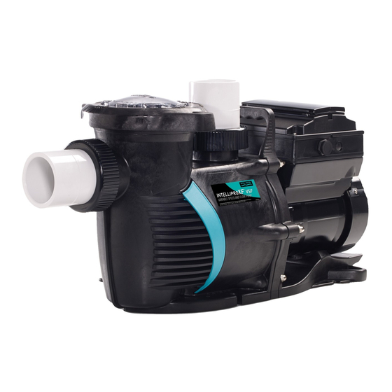
Pentair IntelliFloXF Installation And User Manual
Variable speed ultra energy efficient pump
Hide thumbs
Also See for IntelliFloXF:
- Installation and user manual (36 pages) ,
- Installation and user manual (36 pages)

Related Manuals for Pentair IntelliFloXF


Summary of Contents for Pentair IntelliFloXF
- Page 1 ™ ™ IntelliFloXF and IntelliProXF Variable Speed Ultra Energy Effi cient Pump Installation User’s Guide IMPORTANT SAFETY INSTRUCTIONS READ AND FOLLOW ALL INSTRUCTIONS SAVE THESE INSTRUCTIONS P/N 353061 Rev. A 2/2/12...
- Page 2 , are registered trademarks and/or trademarks of Pentair Water Pool and Spa, Inc. and/or its affi liated companies in the United States and/or other countries. Unless noted, names and brands of others that may be used in this document are not used to indicate an affi...
-
Page 3: Table Of Contents
Setting Speeds 1-8 in Schedule Mode Control Panel Quick Reference Guide External Control ........Features ..........Quick Clean Time Out Quick Reference Guide for the Operator Control Panel on page 35 ™ ™ IntelliFloXF and IntelliProXF Variable Speed Pump Installation and User’s Guide... -
Page 4: Important Safety Instructions
® Pentair Water Pool and Spa PUMP WARNING AND SAFETY INSTRUCTIONS For Pool and Spa Pumps (Non SVRS Pumps) (Pentair Water Pool and Spa ® , Sta-Rite ® , and Pentair Pool Products ® IMPORTANT SAFETY INSTRUCTIONS When installing and using this electrical equipment, basic safety precautions should always be... - Page 5 (Pentair Water Pool and Spa , Sta-Rite , and Pentair Pool Products Warnings and safety instructions for Pentair Water Pool and Spa ® pumps and other related products are available at: http://www.pentairpool.com/pool-owner/safety-warnings/ or call (800) 831-7133 for additional free copies of these instructions.
- Page 6 ® Pentair Water Pool and Spa PUMP WARNING AND SAFETY INSTRUCTIONS For Pool and Spa Pumps (Non SVRS Pumps) ® ® ® (Pentair Water Pool and Spa , Sta-Rite , and Pentair Pool Products THE USE OF UNAPPROVED COVERS OR ALLOWING USE OF THE POOL OR SPA WHEN COVERS ARE MISSING, CRACKED OR BROKEN CAN RESULT IN BODY OR LIMB ENTRAPMENT, HAIR ENTANGLEMENT, BODY ENTRAPMENT, EVISCERATION AND/OR DEATH.
- Page 7 ® Pentair Water Pool and Spa PUMP WARNING AND SAFETY INSTRUCTIONS For Pool and Spa Pumps (Non SVRS Pumps) ® ® ® (Pentair Water Pool and Spa , Sta-Rite , and Pentair Pool Products The Virginia Graeme Baker (VGB) Pool and Spa Safety Act creates new requirements for owners and operators of commercial swimming pools and spas.
-
Page 8: Save These Instructions
® Pentair Water Pool and Spa PUMP WARNING AND SAFETY INSTRUCTIONS For Pool and Spa Pumps (Non SVRS Pumps) ® ® ® (Pentair Water Pool and Spa , Sta-Rite , and Pentair Pool Products General Installation Information • All work must be performed by a qualifi ed pool professional, and must conform to all national, state, and local codes. -
Page 9: Pump Overview
Pump Overview ™ ™ The IntelliFloXF and IntelliProXF Variable Speed pump can be programmed to run at specifi c speeds and time intervals for maximum operating effi ciency and energy conservation for inground pools. ® ® ® The pump can communicate with IntelliTouch... -
Page 10: Installation
Installation Only a qualifi ed service person should install IntelliFloXF ™ and IntelliProXF ™ pumps. Refer to “Pump Warning And Safety Instructions” on pages ii to vi for additional installation and safety information. Location Be sure the pump location meets the following requirements: Pump inlet as close as possible to water level. -
Page 11: Electrical
6. Slide the nut over the ring and attach it to the pump. Step 3 Only install the retainer ring with the tab features pointing away from the nut. ™ ™ IntelliFloXF and IntelliProXF Variable Speed Pump Installation and User’s Guide... -
Page 12: Electrical Wiring Installation
5 feet of the inside walls of the swimming pool, spa, or hot tub. For Canada, a 6 AWG or larger solid copper bonding conductor is required. Pentair offers a selection of 1 and 2-Pole GFCI breakers which offer 6 milliamp personnel protection while meeting NEC 2008 Standards for Pool Pumps. -
Page 13: Operating The Pump
(half way up skimmer opening). If the water level falls below the skimmer opening, the pump will draw air through the skimmer, losing the prime and causing the pump to run dry, resulting in a damaged seal. ™ ™ IntelliFloXF and IntelliProXF Variable Speed Pump Installation and User’s Guide... -
Page 14: Using The Operator Control Panel
• Down arrow: Move one level down in the menu or decrease a digit when editing a setting. • Left arrow: Move cursor left one digit when editing a setting. • Right arrow: Move cursor right one digit when editing a setting. IntelliFloXF ™ and IntelliProXF ™... - Page 15 • Line 1: Key icon indicates password protect mode is active. If password protect is not enabled, no key icon is displayed. • Line 2: Displays current pump speed (RPM). • Line 3: Countdown time and watts • Line 4: Current pump status. ™ ™ IntelliFloXF and IntelliProXF Variable Speed Pump Installation and User’s Guide...
-
Page 16: Starting And Stopping The Pump
The LED above the button will turn on. 3. Press Start/Stop. The pump will quickly change to the selected preset speed. LED lit Speed Speed Speed Speed IntelliFloXF ™ and IntelliProXF ™ Variable Speed Pump Installation and User’s Guide... -
Page 17: Operator Control Panel Menu Guide
Set Speed (750 RPM - 3450 RPM) Default 1000 RPM SET SPEED 40° F - 50° F (4.4° C - 10° C) Default: 40° F (4.4° C) PUMP TEMPERATURE ™ ™ IntelliFloXF and IntelliProXF Variable Speed Pump Installation and User’s Guide... -
Page 18: Pump Settings
® can communicate only to four (1-4) pumps. ™ ™ Note: IntelliFloXF or IntelliProXF pumps cannot be connected in series with other pumps. 1. Be sure the green power LED is on and the pump is stopped. 2. Press Menu. -
Page 19: Set Temperature Unit
4. Press Select. Press Select again to highlight current language in use. 5. Press Enter to select the control panel language. To cancel any changes, press Escape to exit without saving. 6. Press Escape to exit. ™ ™ IntelliFloXF and IntelliProXF Variable Speed Pump Installation and User’s Guide... -
Page 20: Set Min/Max Speeds
6. Press the Up or Down arrows to change the minimum speed setting from 450 to 1700 RPM. 7. Press Enter to save. To cancel, press Escape to exit edit mode without saving. 8. Press Escape to exit. IntelliFloXF ™ and IntelliProXF ™... -
Page 21: Password Protection
2. To enter password, use the left and right arrows to move the cursor and the Up and Down arrow button to scroll through the digit then press the Enter button to confi rm. ™ ™ IntelliFloXF and IntelliProXF Variable Speed Pump Installation and User’s Guide... -
Page 22: Setting Speeds 1-8
MENU Pump Menu: Speeds 1-8 SPEED 1-8 Pump Operating Modes The IntelliFloXF ™ and IntelliProXF ™ Variable Speed pumps can be programmed in three different modes: Manual, Schedule, and Egg Timer. Speeds 1-4 can be programmed in all three modes. Speeds 5-8 can only be programmed in Schedule mode since there are no buttons on the control panel for Speeds 5-8. -
Page 23: Setting Speeds 1-8 In Schedule Mode
Note: When two speeds are scheduled during the same run time the pump will run the higher RPM Speed regardless of Speed # in use. Note: The most recent command, Manual or Schedule, takes priority regardless of speed number RPM. ™ ™ IntelliFloXF and IntelliProXF Variable Speed Pump Installation and User’s Guide... -
Page 24: External Control
12. Press Select to change the time. The cursor will highlight the minutes column. 13. Use Up or Down arrows to change the time from 1 minute to 10 hours. 14. Press Enter to save the time. 15. Press Escape to exit the menu. IntelliFloXF ™ and IntelliProXF ™... -
Page 25: Time Out
If there is still insuffi cient fl ow in the pump basket, the pump will try to prime at the “Maximum Speed” for the amount of time set up in the “Maximum Priming Time” menu. Continue onto the next page for Priming ™ ™ IntelliFloXF and IntelliProXF Variable Speed Pump Installation and User’s Guide... -
Page 26: Setting Priming Features
17. Use the Up or Down arrows to change from 1 second to 10 minutes. Caution: Increasing the time causes the pump to stay in the priming mode longer. 18. Press Enter to save the setting. 19. Press Escape to exit. IntelliFloXF ™ and IntelliProXF ™... -
Page 27: Disabling Priming With An Automation System
4. Once priming is disabled, reinstall the RS-485 communication cable. 1. Disable priming on automation control system. 2. Disconnect the RS-485 communication cable. 3. Disable priming on pump. 4. Reinstall the RS-485 communication cable. ™ ™ IntelliFloXF and IntelliProXF Variable Speed Pump Installation and User’s Guide... -
Page 28: Anti Freeze
40° F to 50° F (4.4° C - 10° C). 14. Press Enter to save the temperature setting. Pump Temperature Note: To cancel any changes, press Escape to exit without saving. 15. Press Escape to exit. IntelliFloXF ™ and IntelliProXF ™ Variable Speed Pump Installation and User’s Guide... -
Page 29: Connecting To An Automation System
For example, Terminal 3 and 4 in IntelliComm will correspond to External Control Program #1. (5 and 6 to Ext Ctrl #2). Use the External Control feature to program the IntelliComm power center. ™ ™ IntelliFloXF and IntelliProXF Variable Speed Pump Installation and User’s Guide... -
Page 30: Connecting To Easytouch And Intellitouch Systems
Control Panel Access Screw Control Panel Access Screw Retaining Screws Front Door (for High Voltage Cover Panel) High Voltage Cover Panel Grommet (to Low Voltage Raceway) IntelliFloXF ™ and IntelliProXF ™ Variable Speed Pump Installation and User’s Guide... - Page 31 12. Switch the power on to the load center. EasyTouch Circuit Board EasyTouch COMPORT (J20) Indoor Control Panel IntelliChlor IntelliPro RF Transceiver IntelliTouch Circuit Board IntelliTouch Personality Board COM PORT (J7/J8) ™ ™ IntelliFloXF and IntelliProXF Variable Speed Pump Installation and User’s Guide...
-
Page 32: Connecting To Suntouch Systems
Connecting the Pump to a SunTouch System ™ ™ The IntelliFloXF and IntelliProXF pumps can be controlled by a SunTouch system via the RS-485 communication cable. Switch OFF main system power to the SunTouch Power Center before making any connections. -
Page 33: Maintenance
Be sure the lid O-ring is properly placed. Seat the lid and locking ring on the pump then turn clockwise until the locking ring handles are horizontal. ™ ™ IntelliFloXF and IntelliProXF Variable Speed Pump Installation and User’s Guide... -
Page 34: Winterizing
If a motor has become wet - let it dry before operating. Do not allow the pump to operate • if it has been fl ooded. • If a motor has been damaged by water it voids the motor warranty. IntelliFloXF ™ and IntelliProXF ™ Variable Speed Pump Installation and User’s Guide... -
Page 35: Servicing
14. Place the seal plate face down on a fl at surface and press out the ceramic part of the mechanical seal. 15. Clean the seal plate, seal housing, and the motor shaft. ™ ™ IntelliFloXF and IntelliProXF Variable Speed Pump Installation and User’s Guide... -
Page 36: Pump Reassembly/Seal Replacement
The pump requires little or no service other than reasonable care. A mechanical seal may occasionally become damaged and must be replaced. Spring Half- Carbon face is Ceramic & Rubber Half- pointing outward White ceramic face is pointing outward IntelliFloXF ™ and IntelliProXF ™ Variable Speed Pump Installation and User’s Guide... -
Page 37: Drive Assembly Removal And Installation
Note: Do not remove Gasket these screws Adapter Connector Orange Motor Post Caps (QTY. 3) If restarting the pump after service or maintenance, please follow the priming instructions from page 5. ™ ™ IntelliFloXF and IntelliProXF Variable Speed Pump Installation and User’s Guide... -
Page 38: Troubleshooting
Indicates excessive supply voltage or an external water source is causing the pump and motor to rotate thereby generating an excessive voltage on the drives internal DC buss. The drive will restart 20 seconds after the over voltage condition clears. IntelliFloXF ™ and IntelliProXF ™... -
Page 39: Problems And Corrective Actions
Lowering speed below 200 RPM may resolve the Issues related to other equipment, such as issue or addition of external manual valve controls, Heat Pumps and Heaters with internal valves may resolve issue. that vibrate. ™ ™ IntelliFloXF and IntelliProXF Variable Speed Pump Installation and User’s Guide... - Page 40 Communication network inoperative. A defective device on the network can inhibit the proper operation of other network device. Devices should be disconnected sequentially until the network starts working. IntelliFloXF ™ and IntelliProXF ™ Variable Speed Pump Installation and User’s Guide...
-
Page 41: Replacement Parts
Replacement Parts Item No. Description IntelliFloXF IntelliProXF Wet End Assembly 400000 401000 Union Kit Without Tap 410020 Power End Assembly w/ Drive 400605 401605 Lid/Locking Ring Assembly 400006 401006 XF Series Replacement Basket 400007z Lid/Locking Ring O-Ring 35505-1440 Drain Plug... -
Page 42: Pump Dimensions
Pump Performance Curves Water Head Dynamic Total IntelliFloXF ™ and IntelliProXF ™ Variable Speed Pump Installation and User’s Guide... - Page 43 Pump Dimensions ™ ™ IntelliFloXF and IntelliProXF Variable Speed Pump Installation and User’s Guide...
-
Page 44: Control Panel Quick Reference Guide
DISABLED/ENABLED (Page 20) Set Speed - Default 1000 RPM SET SPEED 40° F - 50° F (4.4° C - 10° C) Default: 40° F (4.4° C) PUMP TEMPERATURE IntelliFloXF ™ and IntelliProXF ™ Variable Speed Pump Installation and User’s Guide... - Page 45 NOTES ™ ™ IntelliFloXF and IntelliProXF Variable Speed Pump Installation and User’s Guide...
- Page 46 NOTES IntelliFloXF ™ and IntelliProXF ™ Variable Speed Pump Installation and User’s Guide...
- Page 47 NOTES SAVE THESE INSTRUCTIONS...
- Page 48 *353062* LIT. PKG. P/N 353062 *353061* P/N 353061 Rev. A 2/2/12...
Need help?
Do you have a question about the IntelliFloXF and is the answer not in the manual?
Questions and answers