Table of Contents
Advertisement
Advertisement
Table of Contents

Related Manuals for Philips Showline SL NITRO 510


Summary of Contents for Philips Showline SL NITRO 510
-
Page 2: Showline Offices
Document Number: SL NITRO 510 LED STROBE Luminaires Users Version as of: 08 July 2013 SL NITRO 510 LED STROBE Luminaire Installation & User’s Manual ©2013 Philips Group. All rights reserved. -
Page 3: Important Information
SL NITRO 510 LED STROBE Luminaire Installation & User’s Manual IMPORTANT INFORMATION Warnings and Notices When using electrical equipment, basic safety precautions should always be followed including the following: a. READ AND FOLLOW ALL SAFETY INSTRUCTIONS. b. Do not use outdoors. -
Page 4: Table Of Contents
About this Manual ..................................4 Included Items..................................... 4 Accessories ....................................4 SL NITRO 510 LED STROBE Luminaire Power Input Cables (North American Models Only) ........4 SL NITRO 510 LED STROBE Luminaire Accessories..................... 4 SL NITRO 510 LED STROBE LUMINAIRE OVERVIEW SL NITRO 510 LED STROBE Luminaire Components...................... - Page 5 Installation & User’s Manual Strobe Rate DMX Timing Detail .............................. 29 Strobe Duration DMX Timing Detail ............................30 SL NITRO 510 LED STROBE Luminaire RDM Parameter IDs..................... 31 CLEANING AND CARE Special Cleaning and Care Instructions ............................ 34 Front Lens Cleaning.................................. 34 Service and Maintenance ................................
-
Page 6: Preface
Only) Part Number Description SL NITRO 510 LED STROBE Luminaire AC Power Input Cable (39 inches / 1 meter), Powercon with PC1BE Bare End* (*Note, user supplies and installs own AC input connector) SL NITRO 510 LED STROBE Luminaire AC Power Input Cable (39 inches / 1 meter), Powercon with... -
Page 7: Sl Nitro 510 Led Strobe Luminaire Overview
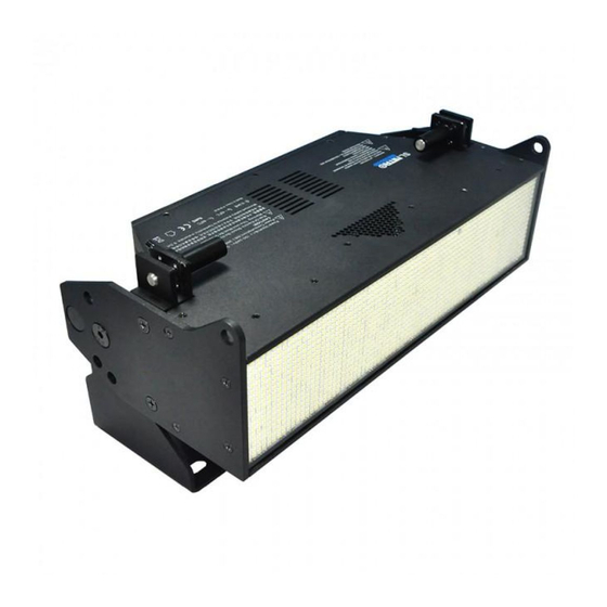
DMX512 / RDM Output RDM Input LCD Display / Menu System* (*refer to "LCD Display / Menu System" on page 6 additional information) Figure 2: SL NITRO 510 LED STROBE Luminaire Components Sh wline SL NITRO 510 LED STROBE Luminaire Components... -
Page 8: Lcd Display / Menu System
(with rotation of menu) Figure 3: LCD Display & Menu System Note: For Menu operation and programming details, refer to "LCD Display and Menu System" on page Sh wline SL NITRO 510 LED STROBE LUMINAIRE OVERVIEW... -
Page 9: Installation And Set Up
INSTALLATION AND SET UP 1. Power Requirements The SL NITRO 510 LED STROBE Luminaire operates on AC input voltages from 100 to 240 VAC. WARNING! This unit does not contain an ON/OFF switch. Always disconnect power input cable to completely remove power from unit when not in use. -
Page 10: Connecting Power
Table 2 on page 8 describes how to connect power to your SL NITRO 510 LED STROBE Luminaire. Field wiring of the SL NITRO 510 LED STROBE Luminaire is straight forward. A total of 3 wires/conductors is supplied from the unit. -
Page 11: Connecting To The Dmx512 Network
DMX connector on the first SL NITRO 510 LED STROBE Luminaire. Another cable runs from the other DMX connector on the first unit to a DMX connector on the next SL NITRO 510 LED STROBE Luminaire (or DMX512 device to be controlled). -
Page 12: Mounting Luminaire
Installation & User’s Manual 4. Mounting Luminaire SL NITRO 510 LED STROBE Luminaires are provided with the ability to hang via truss hooks, clamps, etc. (sold separately). Simply attach hook, clamp, etc. to the SL NITRO 510 LED STROBE Luminaire’s mounts in the provided M9 holes. -
Page 13: Connecting Luminaires Top-To-Bottom
WARNING! Your structure must be capable of properly supporting the weight of multiple connected fixtures. Each fixture must use an approved safety cable attached to a fixed object. Up to twenty SL NITRO 510 LED STROBE Luminaires may be supported when connected using the Quick Connect system. When connecting units together, ensure all Quick-Connect pins are in the "engaged"... -
Page 14: Connecting Luminaires Side-To-Side
Connecting Luminaires Side-to-Side Each SL NITRO 510 LED STROBE Luminaire ships with three Luminaire Connecting Pins as indicated in Figure 9. All three pins are used to connect two luminaires together linearly. Each fixture must be mounted using its own mounting hardware. -
Page 15: Connecting Combined Luminaires Top-To-Bottom
SL BAR 520, preventing the units from spreading apart in the center. • If the bottom of a configuration has two SL NITRO 510 LED STROBE Luminaires below a single SL BAR 520,... - Page 16 SL NITRO 510 LED STROBE Luminaire Installation & User’s Manual vent the spacing between the two SL NITRO 510 LED STROBE Luminaires from spreading apart at the center. Obtain and install: SL BAR 520 LED Luminaire See detail below SL NITRO 510...
-
Page 17: Connecting Combined Luminaires Side-To-Side
"Connecting Luminaires Side-to-Side" on page 12). • Each SL NITRO 510 LED STROBE Luminaire and SL BAR 520 RGBW Luminaire ships with three Luminaire Connecting Pins as indicated in Figure 9. • The three side-to-side pins must be installed per luminaire. -
Page 18: Operation And Programming
Installation & User’s Manual OPERATION AND PROGRAMMING 1. LCD Display and Menu System The SL NITRO 510 LED STROBE Luminaire’s LCD Display and Menu System provides local control for accessing the following fixture’s settings: • Presets (Standard and User Defined) •... -
Page 19: Sl Nitro 510 Led Strobe Luminaire Main Menu Options
Figure 13: LCD Display and Menu System 3. SL NITRO 510 LED STROBE Luminaire Main Menu Options Presets Presets are stored values of the luminaire's LED settings that can be recalled via the menu system or DMX. You can customize up to 31 presets via the menu system. -
Page 20: Effects
SL NITRO 510 LED STROBE Luminaire Installation & User’s Manual Step 6. Press the Check Mark button to save the preset. You will be asked to confirm your saving operation. Step 7. The preset is now saved and can be recalled via the menu or DMX. -
Page 21: Settings/General
No - all menu items are able to be restored to factory defaults. Protected • Preset & Chase - user edited Presets and Chases are not able to be restored to fac- tory defaults. Sh wline SL NITRO 510 LED STROBE Luminaire Main Menu Options... -
Page 22: Settings/Dmx
SL NITRO 510 LED STROBE Luminaire Installation & User’s Manual Table 7: Factory Default Parameters Parameter Description • No - no action. Load Factory • Yes - restore to factory default menu settings. Settings/DMX DMX configuration options are available in the DMX menu. -
Page 23: Status
Step 3. Use the Left and Right arrows to select another digit to adjust. Step 4. Press the Check Mark button to save the new DMX Start Address. Sh wline SL NITRO 510 LED STROBE Luminaire Main Menu Options... -
Page 24: Dimming Curve Selection
PL_Curve * DMX Value DMX Value *PL Curve follows the dimming curve of Philips Selecon PL series LED luminaries. S_Curve Square Curve DMX Value DMX Value Figure 14: SL NITRO 510 LED STROBE Luminaire Dimmer Curves Sh wline OPERATION AND PROGRAMMING... -
Page 25: Master / Slave Operational Mode
5. Master / Slave Operational Mode The Master / Slave Operational Mode allows one SL NITRO 510 LED STROBE Luminaire to act as the "Master" unit and all other connected units are controlled by this unit. When a unit is set to "Slave" mode, it will only listen to and follow any commands sent from a "Master"... -
Page 26: Dmx Control
1 function and other functions follow in sequence. 1. Single Channel Control Mode Table 11 provides DMX channel mapping of the DMX512 control values when the SL NITRO 510 LED STROBE Luminaire is in Single Channel DMX512 mode (as set by the luminaire’s menu system). -
Page 27: Four Channel Control Mode
Installation & User’s Manual 3. Four Channel Control Mode Table 13 provides DMX channel mapping of all DMX512 control values when the SL NITRO 510 LED STROBE Luminaire is in Four Channel DMX512 mode (as set by the luminaire’s menu system). -
Page 28: Zone Mapping Mode
5. Zone Mapping Mode Table 15 on page 27 provides DMX channel mapping of all DMX512 control values when the SL NITRO 510 LED STROBE Luminaire is in Zone Mapping DMX512 mode (as set by the luminaire’s menu system). Figure 16 indicates each Zone in relationship to the front of the luminaire. - Page 29 SL NITRO 510 LED STROBE Luminaire Installation & User’s Manual Table 15: DMX Channel Mapping (Zone Mapping Mode) Default - recom- Parameter Range DMX Range% mended console Description Channel default values Intensity - High Byte 16-bit control for the intensity of the LED settings...
- Page 30 SL NITRO 510 LED STROBE Luminaire Installation & User’s Manual Table 15: DMX Channel Mapping (Zone Mapping Mode) Zone 4 Intensity 0 - 255 0 - 100% 8-bit control of Zone 4 intensity 0 to 255 (full) Controls strobe duration for Zone 4. Refer to "Strobe Duration DMX Timing...
-
Page 31: Strobe Rate Dmx Timing Detail
6. Strobe Rate DMX Timing Detail The chart below describes the Strobe Rate DMX parameters of the SL NITRO 510 LED STROBE Luminaire. Note: Continuous ON Mode illuminates all LEDs without strobing. This feature is activated when Strobe Rate and Strobe Duration are both set to DMX value 255. -
Page 32: Strobe Duration Dmx Timing Detail
SL NITRO 510 LED STROBE Luminaire Installation & User’s Manual 7. Strobe Duration DMX Timing Detail The chart below describes the Strobe Duration DMX parameters of the SL NITRO 510 LED STROBE Luminaire. DMX Value Percent (%) DMX Value Percent (%) -
Page 33: Sl Nitro 510 Led Strobe Luminaire Rdm Parameter Ids
Installation & User’s Manual 8. SL NITRO 510 LED STROBE Luminaire RDM Parameter IDs The following tables outline and describe all the RDM parameters IDs associated with SL NITRO 510 LED STROBE Luminaires. • Table 16, “SL NITRO 510 LED STROBE Luminaire RDM Product Parameters IDs”... - Page 34 SL NITRO 510 LED STROBE Luminaire Installation & User’s Manual Table 18: SL NITRO 510 LED STROBE Luminaire RDM Parameters IDs RDM Parameter IDs Value Comment Implemented Allowed Allowed ■ PRODUCT_DETAIL_ID_LIST 0x0070 ■ ■ DEVICE_MODEL_DESCRIPTION 0x0080 ■ ■ MANUFACTURER_LABEL 0x0081 ■...
- Page 35 2010. Status ID Message Value Data Value 1 Data Value 2 Status ID Description 8100H ALL OK Table 20: SL NITRO 510 LED STROBE Luminaire RDM Manufacturer Specific PIDs for Root Device Type Length Unit Prefix Default Description Allowed Allowed Parameter IDs Category - Manufacturer Defined PIDs - Range is 0x8000-0xffdf (See ANSI E1.20-2010 Standard, Table A-3)
-
Page 36: Cleaning And Care
SL NITRO 510 LED STROBE Luminaire. These types of cleaners or solvents can permanently damage the optics or housings of the fixture. If you have any questions regarding the use or care of your SL NITRO 510 LED STROBE Luminaire, please contact Showline technical support or your local Authorized Dealer. -
Page 37: Technical Specifications
SL NITRO 510 LED STROBE Luminaire Installation & User’s Manual TECHNICAL SPECIFICATIONS 1. SL NITRO 510 LED STROBE Luminaire Operational Specifications Source: High Intensity White LED Array (x1350) Beam Angle: 120 Degrees Light Output: > 68,000 lumens Color Temperature: 6500K...
Need help?
Do you have a question about the Showline SL NITRO 510 and is the answer not in the manual?
Questions and answers