
Related Manuals for SPE EXPERT 1K-FA


Summary of Contents for SPE EXPERT 1K-FA
- Page 1 EXPERT 1K-FA 1KW SOLID STATE FULLY AUTOMATIC LINEAR AMPLIFIER USER’S MANUAL THIRD SERIES CERTIFIED CE/FCC...
- Page 2 User’s manual EXPERT 1K-FA Pag. 2 of 76...
-
Page 3: Table Of Contents
User’s manual EXPERT 1K-FA Main index IMPORTANT ..............................5 PRECAUTIONS..............................5 UNPACKING ..............................8 PANEL DESCRIPTION ........................9 Front Panel ............................9 Rear Panel............................10 GENERAL INFORMATION ......................11 Power supply ..........................11 Input / Output ..........................11 ALC / RELAY / CAT........................11 INTERCONNECTION WITH THE TRANSCEIVER ...............13 USE OF THE LINEAR AMPLIFIER ....................14 SO2R (Single Operator Two Radio) ....................15... - Page 4 18.4 Setup Options Menu........................48 18.5 SET ANTENNA Menu........................50 18.6 SET CAT Menu..........................52 18.7 SPE CAT Settings ........................54 18.8 ICOM CAT Settings ........................54 18.9 KENWOOD, ELECRAFT CAT Settings..................55 18.10 YAESU CAT Settings ........................55 18.11...
-
Page 5: Important
User’s manual EXPERT 1K-FA Congratulations for choosing the SPE EXPERT 1K-FA linear amplifier: It is small, and powerful, it covers the whole frequency range from 1.8 to 54 MHz, completely automatically. All operating conditions (frequency, antenna and tuner) may be controlled from your transceiver. - Page 6 User’s manual EXPERT 1K-FA DO NOT use an extension cord with the AC power cable, as if it is not correctly rated there is a risk of fire or electric shock. Pag. 6 of 76...
- Page 7 User’s manual EXPERT 1K-FA WARNING! DO NOT allow metallic objects or wires to enter inside the amplifier. WARNING! DO NOT obstruct the entries for cooling air at both the sides of the amplifier. Ensure that no object impedes the correct operation of the fans.
-
Page 8: Unpacking
User’s manual EXPERT 1K-FA UNPACKING Remove the packing and carefully check the contents. If you find any damage or if there are any parts missing, contact your retailer immediately. Keep the shipping cartons for future transportation if required. Accessories included in the carton a) Transport carry bag. -
Page 9: Panel Description
User’s manual EXPERT 1K-FA PANEL DESCRIPTION Front Panel Fully Automatic Linear Amplifier POWER DISPLAY TUNE OPERATE TUNE INPUT BAND BAND Expert 1K - FA 1.8 -50 MHz Solid State 1) ON 2) OFF 3) DISPLAY switches between display pages. 4) POWER switches output power from “FULL / HALF“... -
Page 10: Rear Panel
User’s manual EXPERT 1K-FA Rear Panel INPUT 1 INPUT 2 SO2R ANT 3 ANT 4 ANT 1 ANT 2 FUSE 1 FUSE 2 RELAY RELAY RS232 IN 1 IN 2 1) ANT connectors for four possible antennas. 2) SO2R connector for SO2R operations 3) INPUT connectors to connect two exciters. -
Page 11: General Information
Most modern tranceivers have CAT control. In old models often, analog or digital information are sent for changing band. The SPE Expert 1K-FA, thanks to an efficient frequency counter, constantly Pag. 11 of 76... - Page 12 User’s manual EXPERT 1K-FA controls and verifies data coming from the transceiver. Automatic management of bands, antennas and tuner can be done in the following way: In all recent transceivers through CAT connection. In the older ICOM models, through “BAND CONTROL VOLTAGE”.
-
Page 13: Interconnection With The Transceiver
User’s manual EXPERT 1K-FA INTERCONNECTION WITH THE TRANSCEIVER ANTENNAS MULTIBAND TRANSCIEVER SEE MANUAL SO2R INPUT 1 INPUT 2 ANT 1 ANT 2 ANT 3 ANT 4 RELAY FUSE 1 FUSE 2 RELAY RELAY RS232 IN 2 The diagram shows the connections with one transceiver only.To connect the second transceiver repeat the same connections using the port “IN 2“. -
Page 14: Use Of The Linear Amplifier
User’s manual EXPERT 1K-FA USE OF THE LINEAR AMPLIFIER ANT 1 ANT 2 INPUT 1 TUNER ANT 3 INPUT 2 AMPLIFIER ANT 4 SO2R IN 1 IN 2 RELAY RELAY RS 232 The position of the contacts, as shown in the diagram, is the situation of the linear amplifier in OFF state. -
Page 15: So2R (Single Operator Two Radio)
Locating the antennas at some distance from each other, and using appropriate band-pass filters will help to achieve this. SPE cannot be responsible for any damage caused to equipment by using this mode of operating. -
Page 16: External Ground Connection
User’s manual EXPERT 1K-FA EXTERNAL GROUND CONNECTION WARNING! Before connecting an external ground as described below, check with a qualified electrician that your national wiring codes permit such a connection. To reduce TVI, BCI and other RF problems it is sometimes helpful to connect the amplifier to a good RF ground. -
Page 17: Power Supply
User’s manual EXPERT 1K-FA POWER SUPPLY The power supply unit of the SPE Expert 1K-FA has two blocks with two separate power transformers. The first block has regulated and protected voltages, and powers all the electronic circuits for command and control. - Page 18 User’s manual EXPERT 1K-FA 230 VAC blue blue orange blue black black white white brown brown brown 50 W 1 KW TRANSFORMER TRANSFORMER 200 VAC 215 VAC blue blue blue blue orange blue orange blue black black black black white...
- Page 19 User’s manual EXPERT 1K-FA After checking your wiring, re-install the plastic protection, the bottom cover and make sure that, when using 115 and 100 Vac, in “Fuse 1” there is a 1A fuse and in “Fuse 2” there is a 20A fuse (included in the packaging).
-
Page 20: Tuner
User’s manual EXPERT 1K-FA TUNER The amplifier has an automatic tuner that handles load mismatches up to 3:1 VSWR (2.5:1 for 6 m). The circuit used is a PI – L network with excellent harmonic suppression. The amplifier contains a look-up table with all the permitted bands. -
Page 21: Protections / Alarms
RF on the tuner; input power; power combiner balance. Note: unlike all the other linear amplifiers that measure only the reflected power of the antenna, to guarantee a greater protection of the PA, the SPE amplifier measures also the power of harmonics reflected by the band-pass filter. Note: to guarantee the maximum efficiency with the same output power, the PA has three MRF150 push-pull amplifiers connected through a combiner. - Page 22 User’s manual EXPERT 1K-FA Note: before the temperature limits are reached, the output power will change from FULL to HALF automatically, so that transmission with the amplifier may continue with reduced power. In SSB the use of the compressor is recommended only when necessary; this strongly reduces the temperature increase.
-
Page 23: Programming
User’s manual EXPERT 1K-FA 10. PROGRAMMING The three [SET], [◄▲] and [▼►] keys, underlined with an orange line, permit programing the amplifier and they can used in the following way: [SET] Use it to open the menu page, to validate the choices and to exit from the menu page. - Page 24 Select the brand or function: - SPE No further programming is necessary, all is already programmed for the SPE transceivers. - ICOM You need to choose between “CI-V“, or “Band Control Voltage “ if you use the analog connection (read the “CAT CONNECTIONS”...
- Page 25 User’s manual EXPERT 1K-FA c) MANUAL TUNE Allows you to tune the amplifier manually. However, achieving a better setting than that obtained by automatic tuning is very unlikely. Set your exciter to transmit a continuous RTTY or CW signal. Press the [◄ L], [L ►], [◄ C], [C ►] keys until you obtain the minimum SWR.
-
Page 26: Initial Operation Of The Amplifier
User’s manual EXPERT 1K-FA 11. INITIAL OPERATION OF THE AMPLIFIER Before turning ON the amplifier, the following preliminary operations are necessary: Read this manual with care. Be sure that the amplifier is correctly set for the local mains voltage supply. - Page 27 User’s manual EXPERT 1K-FA d) Use of Automatic Tuner To complete the programming it is necessary to match the antennas to the amplifier by operating “TUNE“ (read the “TUNER“ chapter of this manual). We recommend you to select each band (with available antenna) and then program the tuner for the sub-bands within which you will operate.
-
Page 28: Operating
You need few precautions when using the amplifier thanks its high level of automation. SPE reminds you that it is better to lose a fraction of dB in transmitted power, by slightly reducing the drive power, than to over-drive the amplifier and have a poor quality transmission. - Page 29 User’s manual EXPERT 1K-FA be much less. SPE suggests you monitor your transmission to check that the “MIC GAIN” setting is correct. In case of very heavy use, it is advisable to work in “Contest” condition to take advantage of the greater efficiency of the fans.
-
Page 30: Cat Connections
For connections to the Radio connector, refer to the transceiver operating manual. 12.2 SPE In the case of SPE transceivers, it isn’t necessary to make a cable because it is supplied with the transceiver. Pag. 30 of 76... -
Page 31: Icom
User’s manual EXPERT 1K-FA 12.3 ICOM CAT CI–V Interface RX TTL RADIO CONNECTOR DB15 M This interface is standard for all the Icom models equipped with CAT, the cable always terminates to a 3,5 mm. plug BAND CONTROL VOLTAGE Interface... -
Page 32: Kenwood
User’s manual EXPERT 1K-FA 12.4 KENWOOD CAT RS232 Interface RX 232 TX 232 RX 232 (RXD) (TXD) TX 232 RADIO CONNECTOR DB15 M The Radio connector could be DB-9 or DB-25 male connector or female connector (read the specific manual). In the manual also verify if the RTS–CTS link is necessary. -
Page 33: Yaesu
User’s manual EXPERT 1K-FA 12.5 YAESU CAT RS232 Interface RX 232 TX 232 TX 232 (RXD) (TXD) RX 232 RADIO CONNECTOR DB15 M The radio connector may be a DB-9 or DB-25 male connector or female connector (read the specific manual). Verify from the manual if the RTS–CTS link is necessary. -
Page 34: Band Data Interface
User’s manual EXPERT 1K-FA BAND DATA Interface BAND A BAND A BAND B BAND B BAND C BAND C BAND D BAND D RADIO CONNECTO RADIO CONNECTOR DB15 M Without the CAT, the band is commanded by four digital signals (Band A, Band B, Band C, Band D). -
Page 35: Transceivers Of Other Brands
User’s manual EXPERT 1K-FA 12.7 TRANSCEIVERS OF OTHER BRANDS A special link is not necessary as the internal amplifier frequency counter will measure the input frequency and will control the amplifier. Pag. 35 of 76... -
Page 36: Other Connections
User’s manual EXPERT 1K-FA OTHER CONNECTIONS On the 15-pin connector, in addition to the CAT signals, the ALC and RELAY signals are repeated, REMOTE ON and TX – INH are also available. If you use this connector, in some cases, separate ALC and RELAY cables may not be necessary, or it may be possible to turn the amplifier on / off by turning on / off the transceiver (REMOTE ON). -
Page 37: Tx Inh Link
User’s manual EXPERT 1K-FA 13.3 TX INH LINK Some tranceivers have a suitable input (called TX – INHIBIT, LINEAR, MUTE, etc.) that disables transmission. To improve the receive / transmit switching efficiency it is highly recommended, but not mandatory, to connect this input with the pin 13 of the linear connector (TX –... -
Page 38: Transceiver Controlled With A Pc
If the transceiver is controlled with a PC using the CAT utility, the link with the amplifier can be made as described in the following paragraphs. Note: BEWARE, SPE assures only the direct connection between the Linear and the Transceiver. The use of external control software could create malfunctions that must be resolved by the provider of such software. -
Page 39: Rs232 Interface
User’s manual EXPERT 1K-FA 14.2 RS232 INTERFACE KENWOOD OR YAESU RADIO CONNECTOR RS232 RX 232 TX 232 RS232 PC CONNECTOR DB15 M This type of link is the same for KEWOOD, YAESU, TEN-TEC, FlexRadio and ELECRAFT On the other end of the cable it is necessary to link only GND and RX 232. -
Page 40: Ttl Yaesu Interface
User’s manual EXPERT 1K-FA 14.4 5V TTL YAESU INTERFACE YAESU RADIO CONNECTOR RX TTL TX TTL TTL INTERFACE DB15 M The links on the linear connector side are the same. On the other end of the cable it is necessary to link only GND and RX TTL. -
Page 41: Use Of The Rs-232 Port
PC with the supplied cable. On the same website there is, for programmer use, a protocol specification that permits creation of a proper software application. Note: SPE doesn't take any responsibility for these applications. Pag. 41 of 76... -
Page 42: Maintenance
EXPERT 1K-FA 16. MAINTENANCE The Expert 1K-FA linear amplifier doesn’t need internal maintenance because it has a cover without ventilation holes. No tube-type EHT is used so the high voltages present in tube amplifiers, which sometimes attract dirt, are not present. -
Page 43: Characteristics / Specifications
User’s manual EXPERT 1K-FA 17. CHARACTERISTICS / SPECIFICATIONS - The smallest in the world Built-in Power supply and Automatic Antenna Tuner. Dimension: w 28, h 14, d 32 cm. (11.02” W, 5.51” H, 12.60” D) (connectors included). Weight: approx. 20 Kg (19 Kg typ.), 44 lbs (41.8 lbs typ.). - Page 44 - Easy transportation A sturdy carry-bag is supplied for “QSY, FIELD DAY, DX’ PEDITIONS etc.“. - Certifications : CE, FCC . SPE guarantees all previous data on 14 MHz. These specifications are subject to change without notice. Pag. 44 of 76...
-
Page 45: Appendix 1
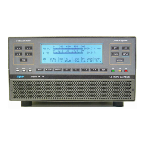
User’s manual EXPERT 1K-FA 18. APPENDIX 1 18.1 Main Display Page (STANDBY Mode). The Main Display Page, just like any other visual page handled by the system, is substantially divided into two parts: · A User Area showing some information/data which vary according to the current working status. -
Page 46: Main Display Page (Tx Exciter)
User’s manual EXPERT 1K-FA 18.2 Main Display Page (TX Exciter). When in STANDBY mode and, having a transceiver connected to one of the two inputs of the linear the TX is switched to, there is a context change and the Main Display... -
Page 47: Alarm History Display Page
User’s manual EXPERT 1K-FA 18.3 Alarm History Display Page. If, in STANDBY mode the [DISPLAY] key is pressed, the Alarm History Page report is displayed; this new page shows in reverse order (the higher numerical index is the last alarm message) all the stored alarm messages since the last stack reset . -
Page 48: Setup Options Menu
User’s manual EXPERT 1K-FA 18.4 Setup Options Menu. The Setup Options Menu can be accessed using the [SET] key while standing in the Main Display Page: [SET] A menu composed of various items which can be selected will be displayed, one item at a time, using the arrow keys ([◄▲] [▼►]);... - Page 49 User’s manual EXPERT 1K-FA The Selected input settings are used for characterizing some parameters relative to both the inputs and they are: · ANTENNA for setting the proper antenna (up to a maximum of two) for every ham band relative to the selected input.
-
Page 50: Set Antenna Menu
User’s manual EXPERT 1K-FA 18.5 SET ANTENNA Menu. [SET] [SET] The SET ANTENNA is for setting the proper antennas for every ham band relative to the two inputs; the available choiches are: · 1, 2, 3, 4 corresponding to the individual output connectors mounted on the rear panel of the amplifier (ANT1, ANT2, ANT3, ANT4). - Page 51 User’s manual EXPERT 1K-FA To edit the antenna setting for another band the arrow key ([◄▲] [▼►]) must be used to select the proper choice and, then, repeat the above described procedure. At the end of the desired setting operations, the SAVE option must be chosen and confirmed using the [SET] key in order to save all the data relative to the bands/antennas to the amplifier’s storage memory;...
-
Page 52: Set Cat Menu
User’s manual EXPERT 1K-FA 18.6 SET CAT Menu [SET] [SET] The SET CAT menu allows setting (or exclusion) of the CAT (Computer Aided Transceiver) interface. This interface, if present in the connected transceiver, allows the amplifier to read frequency and band information from the transceiver even whilst in receive mode. - Page 53 User’s manual EXPERT 1K-FA And, at the end, will be shown the menu for communication speed selection (baud-rate): When the proper choice is made (e.g. 9600 baud) and validated pressing the [SET] key, the Main Display Page will be shown and the Status Bar will be updated according to the change just made.
-
Page 54: Spe Cat Settings
User’s manual EXPERT 1K-FA 18.7 SPE CAT Settings [SET] [SET] [SET] Note: SPE CAT doesn’t need any baud-rate setting since it is internally fixed. 18.8 ICOM CAT Settings [SET] [SET] [SET] [SET] [SET] Note: when CI-V setting is made, the transceiver must be enabled in its “TRANSCEIVE ON”... -
Page 55: Kenwood, Elecraft Cat Settings
User’s manual EXPERT 1K-FA 18.9 KENWOOD, ELECRAFT CAT Settings [SET] [SET] [SET] [SET] Note: KENWOOD CAT interface doesn’t need any model setting. 18.10 YAESU CAT Settings [SET] [SET] [SET] [SET] [SET] Note usually YAESU CAT interfaces run at 4800 baud, but, to make the right choice, it’s better read the transceiver’s documentation carefully. -
Page 56: Ten-Tec Cat Settings
User’s manual EXPERT 1K-FA 18.11 TEN-TEC CAT Settings [SET] [SET] [SET] [SET] Nota: TEN-TEC transceivers come with their respective baud-rate setting fixed by default, so the baud-rate menu is not proposed since it is useless. 18.12 FLEX-RADIO CAT Settings [SET]... -
Page 57: Rs-232 Cat Settings
User’s manual EXPERT 1K-FA 18.13 RS-232 CAT Settings [SET] [SET] [SET] Note: RS-232 CAT interface is an internal link connected to the serial interface connector used for EXPERT’s remotization that has to be made using a suitable PC software. Further details concerning this kind of interface can be found by consulting the document “Communication Protocol Specifications Rev. - Page 58 User’s manual EXPERT 1K-FA When either in STANDBY or OPERATE mode, at any time a short report about the CAT settings related to the two inputs can be obtained by simply pressing the [CAT] key and keeping it held down; an info display screen with a short summary, like the following, will be shown in which it can be seen that: ·...
-
Page 59: Manual Tune Display Page
User’s manual EXPERT 1K-FA 18.15 MANUAL TUNE Display Page. [SET] [SET] This display page is for making some small adjustments to the L-C values of the automatic tuner; this “fine tune” operation could be necessary either if the user cannot reach a good match using the automatic tuning or if he simply wants to apply some manual variations to the current settings. - Page 60 User’s manual EXPERT 1K-FA When in TX mode the frequency readout and the SWR readout displayed in the Status Bar are simultaneously updated. If the applied manual changes are satisfactory, this configuration can be saved (inside the non-volatile memory related to sub-band 6) using the [TUNE] key. By pressing the [SET] key the original tuner setting can be restored instead (i.e.
-
Page 61: Backlight Display Page
User’s manual EXPERT 1K-FA 18.16 BACKLIGHT Display Page. [SET] [SET] This display page allows the backlight setting of the LCD display mounted of the front panel of the amplifier using the arrow keys ([◄▲] [▼►]). The amount set is displayed by the slider setting. -
Page 62: Contest Settings
User’s manual EXPERT 1K-FA 18.17 CONTEST Settings. [SET] This menu item allows setting of the fan’s speed. In detail: · Contest Off the three speeds are set at the following thresholds: o 40 °C (104 °F) On; 37 °C ( 98.6 °F) Off o 70 °C (158 °F) On;... -
Page 63: Beep Settings
User’s manual EXPERT 1K-FA 18.18 BEEP Settings. [SET] This menu item allows you to select if the beep is On or Off following any keystroke coming from the linear amplifier front panel keyboard. To make these changes, press the [SET] key: To leave this menu, the QUIT option has to be chosen and then confirmed using the [SET] key. -
Page 64: Start Settings
User’s manual EXPERT 1K-FA 18.19 START Settings. [SET] This menu item allows to choose, between the two possible Standby/Operate states: · Standby turns the amplifier in the Main Display Page after its power-up. From this display page the user can perform all the operations described till now. -
Page 65: Temp Settings
User’s manual EXPERT 1K-FA 18.20 TEMP Settings. [SET] This menu item allows to choose, between the two possible °C/°F (Celsius degrees, Fahrenheit degrees), the temperature readout inside the Status Bar. This value is taken from the internal heatsink. To make these changes, press the [SET] key: To leave this menu, the QUIT option has to be chosen and then confirmed using the [SET] key. -
Page 66: Operate Mode
User’s manual EXPERT 1K-FA 18.21 OPERATE Mode. In this working mode, the linear amplifier power circuitry is supplied and enabled. It can be activated, from the Main Display Page, either by pressing the [OPERATE] key located of the front panel or by previously setting, from the SETUP OPTIONS menu, the START Operate option. - Page 67 User’s manual EXPERT 1K-FA As previously written, while in OPERATE Mode two distinct display pages can be obtained and they allow to control, together with the Status Bar, the full working of the liear amplifier. To switch back and forth the two display pages, press the [DISPLAY] key.
-
Page 68: Operate Mode And Flex-Radio Cat Interface
User’s manual EXPERT 1K-FA 18.22 OPERATE Mode and FLEX-RADIO CAT interface. When FlexRadio CAT interface is set, there must be programmed the maximum power limits for the transceiver in order to avoid the EXPERT’s overdrive protection system intervention (refer to the Diagnostics section); this is a very important operation since FlexRadio transceivers don’t have any traditional ALC input. - Page 69 User’s manual EXPERT 1K-FA In the following picture can be seen, as an example, the Power Control (15%) setting relative to the same band (20 m), but using the HALF mode selection instead. Once adjusted the proper preset, go to TX mode (RTTY, CW) to verify the output power ATTENTION! It is strongly recommended to start with a low preset value (e.g.
-
Page 70: Diagnostics
User’s manual EXPERT 1K-FA 18.23 Diagnostics. During normal working, the system performs a continuous monitoring of some measurements directly acquired from certain internal test-points; among the most important there are the ones related to the power-supply unit behaviour. When a dangerous situation is going to happen, a “serious” alarm message is raised and the working mode is switched from OPERATE to STANDBY. - Page 71 User’s manual EXPERT 1K-FA While the following table shows all the dynamic warning messages that are not recorded in the Alarm History stack: MESSAGE MEANING 160 m ANTENNA NOT AVAILABLE Antenna not available for 160 m band 80 m ANTENNA NOT AVAILABLE...
-
Page 72: Table
User’s manual EXPERT 1K-FA 19. TABLE BAND TABLE, SUB-BAND, CENTRAL FREQUENCY SUB-BAND [ 0] 1785 [ 1] 1795 [ 2] 1805 [ 3] 1815 [ 4] 1825 [ 5] 1835 [ 6] 1845 [ 7] 1855 [ 8] 1865 [ 9] 1875... -
Page 73: Warranty
In order to not invalidate the warranty service, the original Purchaser must complete the warranty registration card, and send it to SPE no more than 30 days from the date of purchase. If the original Purchaser finds some defects after having received the equipment, he must immediately notify the Distrubutor/Dealer of the defects found by sending the properly filled in REPAIR FORM. - Page 74 User’s manual EXPERT 1K-FA SPE warrant aforesaid items only, and the Purchaser shall have no remedy and no claim for incidental or consequential damages. It is mandatory, when sending SPE equipment to be repaired, to enclose: Invoice of the original purchase...
-
Page 75: Space For The Repairer
User’s manual EXPERT 1K-FA REPAIR FORM MODEL ..... SERIAL NUMBER ....DATE .... - Page 76 User’s manual EXPERT 1K-FA s.r.l. Via di Monteverde, 33 00152 Rome (Italy) Tel. +390658209429 Fax. +390658209647 E-mail: info@linear-amplifier.com Website: http://www.linear-amplifier.com Pag. 76 of 76...
Need help?
Do you have a question about the EXPERT 1K-FA and is the answer not in the manual?
Questions and answers