Table of Contents
Advertisement
Advertisement
Table of Contents

Related Manuals for Freedom 458 Series COMBI

Summary of Contents for Freedom 458 Series COMBI
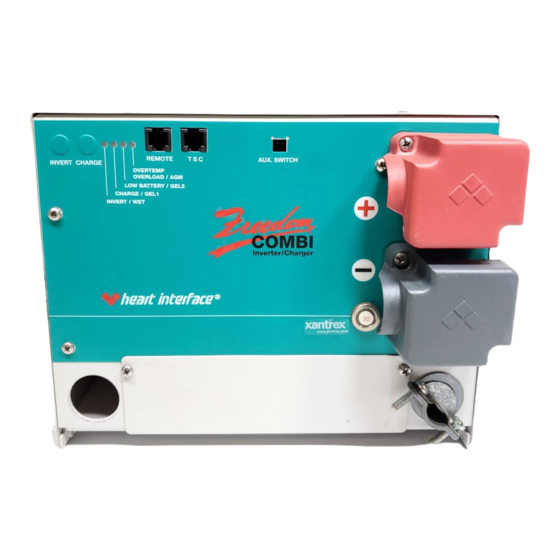
- Page 1 INVERTER/CHARGER Model 10 Model 15, 15 S/D Model 20, 20 S/D Model 25 D/D Model 30, 30 D/D *Manual includes all models of Freedom 458 Series Combi ™ Inverter/Chargers INFORMATION IN THIS MANUAL IS SUBJECT TO CHANGE WITHOUT NOTICE ®...
- Page 2 The statements, specifications and instructions in this publication are believed to be correct. No warranty is made, expressed or implied by the seller or manufac- turer with respect to any results or lack thereof from the use of information in this publication and no liability is assumed for any direct or consequential damages, personal loss or injury.
-
Page 3: Table Of Contents
Connecting Battery Banks ........ 15 Installation ..............16 Before You Install Your Freedom Inverter/Charger ........16 Installing the Freedom Inverter/Charger .... 17 Step 1: Mount the Freedom Inverter/Charger ..........18 Step 2: Connect the AC wiring ......19 Step 3: Install ground fault circuit interrupters .......... - Page 4 Installation Examples ............ 33 Installation Configurations ........33 Installation Option 1 for Freedom 10, 15, 20, 25 D/D, 30, and 30 D/D ..38 Installation Option 2 for Freedom 10, 15, 20, 25 D/D, 30, and 30 D/D ..40 Installation Option 3 for Freedom 25 D/D and 30 D/D .......
-
Page 5: Introduction
NTRODUCTION Thank you for purchasing a Heart Interface Freedom 458 Series Combi Inverter/Charger. Heart Interface takes pride in manufacturing quality products specifically designed to meet your power requirements. Freedom Inverter/Chargers provide silent, efficient and reliable AC power for a variety of applications. They feature “hands-free”... -
Page 6: Warranty
Warranty Your Heart Interface Freedom 458 Series Combi Inverter/ Charger has a 30-month limited warranty, from date of pur- chase. Terms of this warranty are detailed on the warranty registra- tion card. Please complete this card and return it to Heart Interface. -
Page 7: Automatic 3-Stage Battery Charging
Automatic 3-Stage Battery Charging The Freedom Inverter/Charger is designed to rapidly and optimally charge wet, gel, or Absorbed Glass Mat cell deep- cycle batteries. The battery charger automatically proceeds through the bulk, acceptance, and float charging stages, resulting in an efficient, complete charge. -
Page 8: Inverter Idle Circuit
This automatic, energy saving feature reduces battery power consumption when you do not have an AC load connected to the Freedom Inverter/Charger’s output. You can use the Remote Control Panel or LINK instrument to adjust the idle threshold. The factory default setting is 5 watts. -
Page 9: Remote Controls
EMOTE ONTROLS You can purchase two types of Heart Interface remote controls to use with your Freedom Inverter/Charger: 1. Remote Control Panel 2. LINK instruments Installation and operations instructions for your remote control are packed with the panel. Remote Control Panel The remote control panel has: •... - Page 10 LINK 2000 The LINK 2000 monitors two battery banks. LINK 2000R The LINK 2000R adds the ability to regulate an engine-driven alternator. The precision regulator in the LINK 2000R allows the alternator to be controlled as a 3-stage battery charging system.
-
Page 11: Batteries
ATTERIES Selecting Batteries When you choose your batteries, look for true, deep cycle batteries that are rated in amp-hours (AH) and sized to match your power requirements. Use the “Typical Power Consump- tion” chart on page 10 to help you calculate how many batter- ies you need to purchase. -
Page 12: Gel Cell Batteries
you should add distilled water. Follow the battery manufacturer’s recommendations for maintenance. • Never allow the tops of the battery plates to be exposed to air. This will contaminate the battery cells. When neces- sary, add distilled water to the battery. •... -
Page 13: Battery Discharge/Charge Cycling
Battery Discharge/Charge Cycling Deep-cycle batteries can be discharged about 80% of capacity before damage occurs. Shallow cycling will result in a longer battery life. A 50% discharge cycle is generally considered to be a good compromise between long battery life and battery bank size. -
Page 14: Typical Power Consumption
Amp-Hour Consumption Formulas (AC Amps x 10) x 1.1** x Hours of Operation = DC Amp-Hours (AC Watts/DC Voltage*) x 1.1** x Hours of Operation = DC Amp-Hours (AC Volt-Amps/DC Voltage*) x 1.1** x Hours of Operation = DC Amp-Hours *DC Voltage is 12, 24 or 32 volts, depending on your system. - Page 15 Typical Power Consumption , t l " 3 " 9 n i l " 8 l l i r . t f . t f l l u *Refrigeration is typically calculated using a 1/3-duty cycle.
-
Page 16: Connecting Batteries
Connecting Batteries In most cases, you will be using a bank of two or more batter- ies with your Freedom Inverter/Charger. Depending on your batteries’ voltage, you may connect batteries: • In series to increase the battery bank’s voltage • In parallel to increase the battery bank’s amp-hour capac- You should increase the voltage of a battery bank connected in series until it matches your system’s voltage. -
Page 17: Connecting Batteries In Series
1. Attach the battery cable to the first battery’s positive (+) terminal. 2. Attach the other end of the battery cable to the second battery’s negative (-) terminal. 3. To connect the battery bank to the Freedom Inverter/ Charger, see Installation “Step 4: Connect the battery cables” on page 23. -
Page 18: Connecting Batteries In Parallel
(+) terminal. 4. Attach the other end of the battery cable to the second battery’s positive (+) terminal. 5. To connect the battery bank to the Freedom Inverter/ Charger, see Installation “Step 4: Connect the battery cables” on page 23. -
Page 19: Connecting Battery Banks
4. Attach the other end of the battery cable to the second battery bank’s empty positive (+) terminal. 5. To connect the battery bank to the Freedom Inverter/ Charger, see Installation “Step 4: Connect the battery cables” on page 23. -
Page 20: Installation
NSTALLATION We recommend that an authorized Heart Interface technical dealer or experienced electrician install your Freedom In- verter/Charger. Consult the NEC and your local electrical codes for electrical wiring specifications. Confirm that your shipping carton contains: • Inverter/charger • Owners manual (this manual) •... -
Page 21: Installing The Freedom Inverter/Charger
Installing the Freedom Inverter/Charger Determine the appropriate installation for your model and your intended usage by referring to the “Installation Ex- amples” on pages 33-50 before you install your Freedom Inverter/Charger. To install your unit follow the steps listed below. Each step is covered in detail in the following sections. -
Page 22: Step 1: Mount The Freedom Inverter/Charger
Make sure all wiring conforms to local and national elec- trical codes. If in doubt, consult a qualified electrician. Step 1: Mount the Freedom Inverter/Charger Determine where to mount the unit Follow these guidelines when you determine where to mount the unit: 1. -
Page 23: Step 2: Connect The Ac Wiring
• Areas which require ignition-protected equipment. 2. Mount the unit as close to the battery bank as possible. The overall length of each battery cable should be less than 10 feet. 3. Make sure the unit is not in the presence of flammable fumes. - Page 24 Example of Single Input/Dual Output Model Strain Strain Relief Relief AC GROUND INPUT STRIP OUTPUT 1 OUTPUT 2 • If there is 30-amp service to the inverter/charger, additional 20-amp (15-amp in Canada) circuit breakers are required between the inverter/charger and the loads.
- Page 25 Warning Do not connect incoming AC power, from any source, to the AC output of the Freedom Inverter/Charger. This is called back- feeding. Back-feeding will damage the unit and it will void your warranty. The OVERTEMP/OVERLOAD and the LOW BATTERY LEDs will blink rapidly when the unit is improperly wired and is being back-fed.
- Page 26 • If your unit has dual AC outputs, and you are using both AC outputs, feed two AC output wire(s) through the strain relief and into the AC wiring compartment. 4. Strip 1/2 inch of insulation off each conductor. 5. Connect each wire to the unit’s AC output wires: •...
-
Page 27: Step 3: Install Ground Fault Circuit Interrupters
• Refer to GFCI manufacture’s recommendations and to the NEC requirements for proper installation. Step 4: Connect the battery cables Caution Do not connect the Freedom Inverter/Charger to the engine starter battery. Warning The Freedom Inverter/Charger is not DC reverse polarity protected. - Page 28 Other heat shrink may be used if it is UL Listed or UL Recognized, and you follow the manufacturer’s directions. Installing the battery cables 1. Attach the negative (-) battery cable to the Freedom In- verter/Charger. Follow the battery hardware stack up diagram. The negative cable may be black or yellow for...
- Page 29 Battery Cable Hardware Stackup Diagram Bolt Lock Washer Flat Washer Battery Cable with Ring Terminal Inverter/Charger 2. Tighten the battery terminal bolts to a torque value be- tween 160 inch-pounds and 180 inch-pounds. 3. Install the black battery terminal cover on the negative terminal.
-
Page 30: Step 5: Install Battery Cable Fuses
(+) cable from the unit to positive terminal of the first battery. 10. Connect the negative (-) cable from the Freedom Inverter/ Charger directly to the negative post of the house or auxiliary battery bank or the ground side of a current shunt. - Page 31 Recommended Fuses (UL Listed Class T JLLN with a DC rating) & & & & & & & & & & & & * Compression/Ring Terminal ** Ring/Ring Terminal To install the fuse and fuse holder 1. Connect the positive (+) inverter cable to the fuse holder. Assemble the nut and washers in the order shown.
-
Page 32: Step 6: Install The Optional Remote Control Panel Or Link Instrument
+ (red) 4. Install protective cover for the fuse. Step 6: Install the optional Remote Control Panel or LINK instrument 1. Route the remote cable. 2. Connect the cable to the Remote jack on the front of the Freedom Inverter/Charger. -
Page 33: Step 7: Install The Temperature Sensitive Charging (Tsc) Sensor, If You Are Using It
1. Connect the ring terminal end of the cable to the a battery post in the Freedom Inverter/Charger’s battery bank. 2. Route the TSC sensor cable to the Freedom Inverter/ Charger. 3. Plug the end of the RJ11 cable into the TSC jack on the front of the unit. - Page 34 If you are using a remote control, turn on the inverter with the button on the Remote Control Panel or LINK instru- ment. The Freedom unit will produce a slight tick-tick sound. If using a Remote Control Panel or LINK instrument the INVERT/CHARGE LEDs will illuminate and the voltage indicator will display the battery voltage.
- Page 35 Eliminating back-feed Warning Use caution when handling the AC output wires. They may have live voltage. 1. Disconnect the shore power. 2. Disconnect the AC output wires from the inverter. 3. Make sure the inverter is off. 4. Connect a voltmeter to the black and white wires that were attached to the inverter’s output.
- Page 36 Test the transfer function 1. Turn the INVERT ON; the green LED should blink. 2. Remove shore power. The inverter should automatically pick up the AC load when shore power is removed. Repeat the test for transfer and battery charger for your gen- erator, if you have one.
-
Page 37: Installation Examples
We recommend that you consult a qualified electrician for proper installation. Installation Configurations The following are the most commonly used installations involving specific Freedom Inverter/Charger models, shore power connections, optional generator power, and AC load configurations. Input/ Output... - Page 38 Input/ Output Installation Model Modes Option External AC Power Source • 15 S/D Single/ 30-amp shore power source • Dual 30-amp breaker from panel fed by 50-amp, 120-volt, single phase (3-wire) shore power source • 30-amp breaker from one leg of a 50-amp, 120/240-volt, split phase (4-wire) shore power source •...
- Page 39 Input/ Output Installation Model Modes Option External AC Power Source • 25 D/D Dual/ Two separate 30-amp shore power sources • Single Two 30-amp breakers from panel fed by 50- amp, 120-volt, single-phase (3-wire) shore power source • Two 30-amp breakers from 50-amp, 120/240- volt, split phase (4-wire) shore power source •...
- Page 40 Input/ Output Installation Model Modes Option External AC Power Source • 30 D/D Dual/ Two separate 30-amp shore power sources • Dual Two 30-amp breakers from panel fed by 50- amp, 120-volt, single-phase (3-wire) shore power source • Two 30-amp breakers from 50-amp, 120/240- volt, split phase (4-wire) shore power source •...
-
Page 42: Installation Option 1 For Freedom 10, 15, 20, 25 D/D, 30, And 30 D/D
Shares power with the AC loads. It can transfer up to 30-amps. Charger Installation Notes 1. When installing a Freedom 25 D/D or 30 D/D model, the AC Input 2 and AC Output 2 wires are not used. They must be capped off. -
Page 44: Installation Option 2 For Freedom 10, 15, 20, 25 D/D, 30, And 30 D/D
Installation Option 2 for Freedom 10, 15, 20, 25 D/D, 30, and 30 D/D Single Input/Single Output Inverter Mode • Single 30-amp shore power source External AC Power Source • 30-amp breaker from a panel fed by a 50-amp 120-volt single phase (3-wire) shore power source •... - Page 45 battery chargers, should be connected to the Main AC Panel. Power for these loads are supplied by shore or generator power that is connected to the main panel. This split load approach will help avoid problems such as overloading the inverter or rapidly discharging the battery bank.
-
Page 47: Installation Option 3 For Freedom 25 D/D And 30 D/D
Installation Option 3 for Freedom 25 D/D and 30 D/D Dual Input/Single Output Inverter Mode • Two separate 30-amp shore power sources. Both neutrals External AC Power and both “hots” must be kept separate. Source • Two 30-amp breakers from panel fed by 50-amp 120-volt, single phase (3-wire), shore power source •... - Page 48 5. The inverter’s AC Output 2 supplies a separate sub panel. The appliance and outlet loads are then supplied with power from the inverter hot and inverter neutral bus in the sub panel. 6. If a generator is installed in the system, use a break-before- make AC transfer switch to switch between shore power and generator power.
-
Page 50: Installation Option 4 For Freedom 25 D/D And 30 D/D
Installation Option 4 for Freedom 25 D/D and 30 D/D Dual Input/Dual Output Inverter Mode • Two separate 30-amp shore power sources. Both neutrals External AC Power and both “hots” must be kept separate. Source • Two 30-amp breakers from panel fed by 50-amp 120-volt, single phase (3-wire), shore power source •... - Page 51 If only AC Input 2 is supplied power, the unit will not charge. It will only transfer 30-amps through to the in- verter loads connected to AC Output 2. 4. The inverter’s AC Outputs 1 and 2 supply a separate sub panel.
-
Page 53: Installation Option 5 For Freedom 15 S/D And 20 S/D
Installation Option 5 for Freedom 15 S/D and 20 S/D Single Input/Dual Output Inverter Mode • Single 30-amp shore power source External AC Power Source • 30-amp breaker from panel fed by 50-amp 120-volt single phase (3-wire) shore power source •... - Page 54 Only lighter appliance and outlet circuits should be connected to AC Output 1 and AC Output 2. These loads are supplied power through the inverter in charge/transfer mode, or by the inverter in invert mode. The charger shares power with the inverter loads only and can transfer up to 30-amps.
-
Page 55: Operation
OVERLOAD / AGM LOW BATTERY / GEL2 CHARGE / GEL1 INVERT / WET The Freedom Inverter/Charger performs three distinct func- tions: 1. DC to AC power inverting. This provides 120-volt AC power from deep cycle DC batteries. 2. Automatic transfer switching between inverter power and incoming AC power. -
Page 56: Selecting The Battery Type
Selecting the Battery Type The selected battery type tells the Freedom Inverter/Charter what voltage settings to use. The unit remembers which type of battery you select. It will use this type each time you con- nect input power. 1. If the inverter is on, i.e., the INVERT LED is a steady green or blinking, press the INVERT button for 5 seconds. -
Page 57: Reading The Status Leds
Reading the Status LEDs For further information, refer to the “Troubleshooting LED Status” chart on page 54. State Status INVERT Solid Green Unit is in invert mode. Blinking Slowly Inverter is in standby mode, with AC power (once a second) applied, and the transfer switch engaged. -
Page 60: Power Inverting
120 volt AC power at the crystal controlled, 60 Hz frequency. Your unit is rated at: Freedom 10 1000 watts Freedom 15 & 15 S/D 1500 watts Freedom 20 & 20 S/D 2000 watts Freedom 25 D/D... -
Page 61: Battery Shutdown
Battery Shutdown Low Battery Voltage Shutdown If the battery voltage drops to 10.0 volts, the inverter will automatically shut off. Charge the batteries to 13.5 volts to automatically resume operation. High Voltage Battery Shutdown Voltage shutdown also occurs at 15.5 volts. Check all DC sources on the system to find out why you have excessive voltage, and correct the problem. -
Page 62: Battery Charging
Automatic 3-Stage Battery Charging When you connect AC power to the Freedom Inverter/ Charger input, the battery charger automatically turns on. If you are using the Remote Control Panel or the LINK instru- ment, use it to turn the charger on. - Page 63 Automatic 3-Stage Battery Charging Time vs. DC Current in Amps Time vs. DC Voltage in Volts (maintenance) (rapid) (constant voltage) Accept Float Bulk 16.0 15.0 14.0 13.0 12.0 Time IDC Out T ime (minutes) (depends on battery bank size & level of discharge) VDC Out The battery charger stages are: 1.
- Page 64 Stage 1—Bulk Charge During the bulk charge stage most of the energy that has been consumed during discharge is returned to the battery bank. The charger enters this phase as soon as you turn the charger on, i.e., as soon as you connect AC power to the appropriate AC input.
- Page 65 Acceptance to Float Transition Points Model Maximum Output Current Freedom 10 10 Amps DC Freedom 15 & 15 S/D 12 Amps DC Freedom 20 & 20 S/D 15 Amps DC Freedom 25 D/D 15 Amps DC Freedom 30 D/D...
- Page 66 Stage 3—Float Charge When the acceptance stage is completed, the charge current will shut off. The Freedom Inverter/Charger monitors the battery voltage while it drifts down from the acceptance charge voltage limit. When it reaches the float voltage set point, the float charge stage engages.
- Page 67 The battery charger remains in the float charge stage until: • You disconnect incoming AC power from the charger • You press CHARGE on the unit to turn the charger off • You turn the charger off using the Remote Control Panel or LINK instrument Battery Charger Float Voltage Settings in DC Volts F º...
-
Page 68: Optional Equalizing Charge
Optional Equalizing Charge Stage 4 - Equalizing Charge (Optional) Warning Do not equalize gel cell or AGM batteries. The equalizing charge is a controlled, over-charge cycle. During the cycle, the battery voltage will increase to the equalizing voltage. This will cause the battery bank to gas profusely. - Page 69 To equalize the batteries Equalizing is recommended only for wet cell batteries. Do not equalize gel cell or AGM batteries. 1. Do not equalize the batteries until they have completed the full 3-stage charge cycle. 2. Remove all loads from the DC system. Some DC loads may not tolerate the high charge voltage.
-
Page 70: Temperature Sensitive Charging (Tsc)
To cancel equalizing • Interrupt the AC power to the charger at any time during the cycle. Temperature Sensitive Charging (TSC) When the battery temperature sensor is connected to the unit and to the batteries, the charge voltage is controlled based on battery temperature. -
Page 71: Resetting Circuit Breakers
ESETTING IRCUIT REAKERS Your Freedom Inverter/Charger has the following supple- mental circuit breakers: • S/D models have output circuit breakers (OUT1 and OUT2) to protect the output AC circuits. These can be used for branch circuit protection. • INVERT/CHARGE breaker protects against sustained inverter/charger over current conditions. -
Page 72: Specifications
PECIFICATIONS...
Need help?
Do you have a question about the 458 Series COMBI and is the answer not in the manual?
Questions and answers