
Summary of Contents for Alpermann+Velte AV-MTD G 30 TTT
- Page 1 Operating Manual Version: 3.5 February 4, 2011 LTC generators + central units of the MTD Time-Timer-Time-Code System AV-MTD G 30 TTT...
-
Page 3: Table Of Contents
Operating Manual AV-MTD G 30 TTT TABLE OF CONTENTS Page A1 SAFETY INSTRUCTIONS A2 COPYRIGHT A3 CE-DECLARATION FUNCTIONS OVERVIEW REAR PANEL AND SPECIFICATION DESCRIPTION OF KEYS THE 8-DIGIT DISPLAY AND THE LEDS DESCRIPTION OF THE MENU LINES USER BITS MODE... -
Page 4: A1 Safety Instructions
Use a moist soft textured fabric cloth when cleaning the housing. Do not use polish or any other cleaning agents. Repairs: The AV-MTD G 30 TTT does not require any extra maintenance. There are no user serviceable parts inside the device. Repairs should be sent to an authorized service partner. -
Page 5: A3 Ce-Declaration
Operating Manual AV-MTD G 30 TTT A3 CE Declaration of Conformity Alpermann+Velte Electronic Engineering GmbH Otto-Hahn-Str. 42 D-42103 Wuppertal herewith declare under our sole responsibility that the G 30 TTT meets the intent of the following directives, standards and specifications:... -
Page 7: Functions Overview
Page 1 Functions Overview Alpermann+Velte has developed a system for Multiple Time Displays (MTD). A MTD system consists of a central generator unit, digital displays and/or analogue clocks, and user console(s). The central generator unit outputs a special LTC format. This LTC will henceforth denoted as LTC(MTD). -
Page 8: Rear Panel And Specification
Operating Manual AV-MTD G 30 TTT Page 2 Rear Panel and Specification BNC insul./SMA 75Ohm DSUB9M DSUB9F DSUB9F XLR3M XLR3F XLR4M Antenna Loop DC In LTC Out LTC In (optional) on/off Option Data Out: Power In: LTC Out: DCF77/GPS DCF77/GPS... -
Page 9: Description Of Keys
Operating Manual AV-MTD G 30 TTT Page 3 Description of Keys real-time The time information of the LTC is generated identical to the “real-time“. “Real- time“ is an internal clock, which is regulated by the built-in or external DCF77 or GPS receiver, or by external operation (MTD user console). -
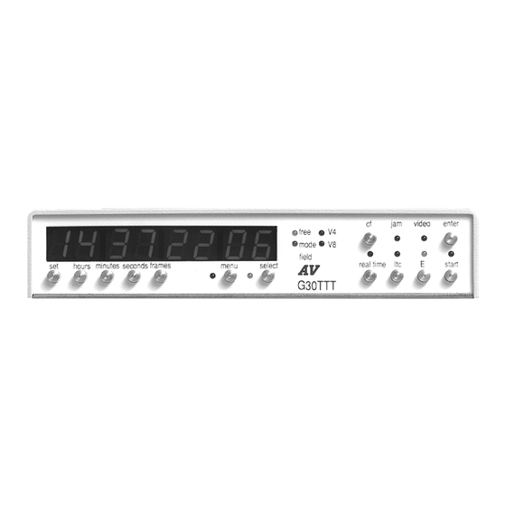
Page 10: The 8-Digit Display And The Leds
Operating Manual AV-MTD G 30 TTT Page 4 The 8-Digit Display and the LEDs The 8-digit display generally displays the time information of the generated LTC as “hours minutes seconds frames“. With the operating mode “time E“ (E key) one frame will be added to the generated value. -
Page 11: Description Of The Menu Lines
Operating Manual AV-MTD G 30 TTT Page 5 Description of the Menu Lines Pressing the menu key switches the menu lines on or off. After power-on the last selected menu line is displayed (the menu LED lights up). A menu line serves to indicate actual settings or executable functions. - Page 12 Operating Manual AV-MTD G 30 TTT Page 6 F reset Pressing the enter key the factory settings will be stored in the backup memory and in the actual area. Attention: This action will restart the G 30 TTT just like a power-on! REAL on (off) Pressing the enter key will switch between on and off.
-
Page 13: User Bits Mode
Operating Manual AV-MTD G 30 TTT Page 7 User Bits Mode Basically G30TTT generates the LTC(MTD), i.e. the user bits carry data for the use of the MTD system. But it is also provided to switch the user bits mode. In principle three basic modes can be defined: •... -
Page 14: Offset To Reference Time Input
Operating Manual AV-MTD G 30 TTT Page 8 Offset to Reference Time Input The reference time comes from an external or built-in GPS or DCF77 receiver. Now it is possible to create a time zone selecting a full hours offset. -
Page 15: Stored Data And Factory Settings
Operating Manual AV-MTD G 30 TTT Page 9 Stored Data and Factory Settings Settings which have been made via G 30 TTT or via a MTD user console will be stored. In detail these settings are as follows: Settings via G 30 TTT Factory settings •... - Page 16 Operating Manual AV-MTD G 30 TTT Page 10 1. After power-on “S“ will be transferred to “W“ if all data in “S“ are reasonable. 2. In case of a storage failure “S“ will be overwritten with “F“, then continued as in 1.
-
Page 17: After Power-On
Operating Manual AV-MTD G 30 TTT Page 11 After Power-On After power-on the last stored data will be tested. In case of a storage failure a “reset“ is made, with the display indicating reset. After that, or in case of valid data, status reports are indicated in two steps, and all status LED’s are lit up. -
Page 18: Receiving "Real-Time" Via Dcf77 Or Gps
Operating Manual AV-MTD G 30 TTT Page 12 Receiving “Real-Time“ via DCF77 or GPS There are two standard configurations: • G 30 TTT with built-in DCF77 receiver. The antenna has to be connected at the insulated BNC socket at the rear panel. Three LED’s at the front of G 30 TTT indicate the status of the built-in receiver: LED free (red) = free-run mode. -
Page 19: Option: Vitc Generator
Operating Manual AV-MTD G 30 TTT Page 13 “Real-time“ in the MTD timer system: The “real-time“ is encoded in the user data of the LTC(MTD) and may be displayed on the displays of the MTD system. This time is synchronised every second to the receiver clock. If there is no receiver built-in or connected to the G 30 TTT, “real-time“... -
Page 20: Option: Receiving "Real-Time" Via Ltc Input
Operating Manual AV-MTD G 30 TTT Page 14 Option: Receiving “Real-Time“ via LTC Input With this special feature G30TTT receives “real-time” (time and date) via a separate LTC input: 75Ohm DSUB9F XLR3F DSUB9F XLR4M XLR3M XLR3F Loop DC In LTC Out... - Page 21 Operating Manual AV-MTD G 30 TTT Page 15 SW1=ON Date according to EBU Technical Information I29-1995 (BBC format): Digit 1 (BG1) reserved bits = 0. Digit 2 (BG2) units of the day 4 bits, LSB = bit 12 Digit 3 (BG3)
Need help?
Do you have a question about the AV-MTD G 30 TTT and is the answer not in the manual?
Questions and answers