Table of Contents
Advertisement
AM/FM Receiver, CD/MP3/WMA Player with
USB Port, Aux In, & Detachable Face
• AM/FM MPX STEREO
• MP3 / WMA WITH ID3 DISPLAY
• ASPS MEMORY CONTROL
• AUTO SEEK UP / DOWN
• FM STEREO / MONO
• 30 PRESET MEMORY
• MIX BAS / TRE / BAL / FAD SWITCH
• AUTO CD PLAY / RADIO
• AUTO POWER LOADING
• LOUDNESS CONTROL
• MUTE SOUND CONTROL
• USB CONTROL FOR MP3 / WMA
VRCD400-SDU
OWNER'S MANUAL
• WIRE HARNESS ON PLUG
• DIGITAL LCD DISPLAY
• DUAL CHANNEL LEVEL METER
• TIME CLOCK DISPLAY
• PRESET EQ (POP, ROCK,
FLAT, CLASSIC)
• BUILT IN NOISE FILTER
• BUILT IN RCA OUTPUT
• SUBWOOFER OUTPUT
• AUXILIARY INPUT
• AUTO ANTENNA ACTIVATOR
• INFRA RED REMOTE CONTROL
Advertisement
Table of Contents

Related Manuals for Virtual Reality VRCD400-SDU


Summary of Contents for Virtual Reality VRCD400-SDU
- Page 1 VRCD400-SDU OWNER’S MANUAL AM/FM Receiver, CD/MP3/WMA Player with USB Port, Aux In, & Detachable Face • AM/FM MPX STEREO • WIRE HARNESS ON PLUG • MP3 / WMA WITH ID3 DISPLAY • DIGITAL LCD DISPLAY • ASPS MEMORY CONTROL • DUAL CHANNEL LEVEL METER •...
-
Page 2: Table Of Contents
In the rare event that your VRCD400-SDU Compact Disc Player and AM/FM Stereo Receiver with USB Port and AUX In contains a damaged or missing item, does not... -
Page 3: Precautions
Precautions • This unit will only play the following discs. Type of disc Label on the disc Recorded material Size of disc CD, MP3, & WMA Audio only 12 cm • Do not attempt to modify the unit. • Do not operate in extremely high or •... -
Page 4: Notes On Installation
Notes on Installation • Disconnect negative battery terminal before starting installation. Consult the vehicle’s owner’s manual for proper instruction. • The unit is designed for a 12Volt DC negative ground operation system only. Before installing the unit, make sure your vehicle is a 12Volt DC negative ground system. •... -
Page 5: Before You Install
1-800-445-1797 and our in-house technical service team will answer your installation questions. Contact the vehicle's manufacturer for vehicle specific instructions, or consider having the VRCD400-SDU professionally installed. IMPORTANT: Remove the two transport screws from the top of the unit before installing. -
Page 6: Installation (Din Front Mount)
INSTALLATION DIN FRONT-MOUNT (Method A) After inserting the Mounting Sleeve Bend the tabs into the dashboard, select tabs on 1. Dashboard to secure the top, bottom, and sides, then bend Mounting Sleeve in the dashboard. them to secure the mounting sleeve in the dash board.(Fig. -
Page 7: Installation (Vehicle's Brackets)
INSTALLATION DIN REAR-MOUNT (Method B) Installation using the screw holes on the both sides of the unit. 1. Screw holes on the side of the unit. 2. Screws. Use either truss screws (5 x 8mm) or flush surface screws (4 x 8mm), depending on the shape of the screw holes in the bracket. -
Page 8: Wiring Connections
INSTALLATION WIRING CONNECTIONS... -
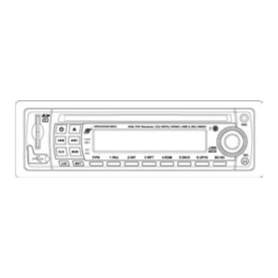
Page 9: Location Of The Controls
Location of the Controls 1. SD Card Slot 14. 4/Random 2. Previous Track/Change Frequency 15. 3/Repeat 3. Power 16. 2/Introduction 4. Eject Disc 17. 1/Pause 5. Next Track/Change Frequency 18. F/PS 6. Disc Slot 19. Mode 7. Liquid Crystal Display 20. -
Page 10: Remote Control
REMOTE CONTROL This unit comes with a full remote control system. The CR-2025 Lithium battery is an included item with the remote control Operating the remote control Aim at the face panel of the CD Receiver, the maximum distance at which signals can be received is about 6M. -
Page 11: Basic Operation
Basic Operation 1. Tuning the Unit On / Off speakers. Press the any button to turn the unit on, the 10. Subwoofer Control display will show a message WELCOME Press and hold the SEL button until LCD to indicate it is ready for use. Press and hold display “DSP OFF”. -
Page 12: Radio Operation
Radio Operation 1. Choose Radio Frequency band. There are 5 bands and 30 available Choose American or European Frequency preset stations slot. 3 FM bands, F1, F2, by selecting the A/E switch. A is for and F3 making a total of 18 preset stations American Frequencies (87.7, 87.9, etc) and in FM band. -
Page 13: Cd Operation
CD Operation 1. Insert/Eject CD 5. Scanning Tracks Insert a disc into CD slot with label side On the Remote or Head Unit, press the up. The disc will be automatically loaded No.2/INT Button to play the first 10 sec- into the unit, even when it is off or at radio onds of each track. -
Page 14: Mp3/Wma Operation (Cd)
MP3/WMA Operation 1. Insert/Eject CD Button is released. On the Remote Control, Insert a disc with MP3 and or WMA files use the |<< or >>| Buttons. into the CD slot with label side up. The disc will be automatically loaded into the 4. - Page 15 MP3/WMA Operation B. Track Search change the character. Press the SEL button Press the F/PS Button and the display will once to confirm the character entered and show “TRK SCH”. Press the SEL Button so advance to the next character. After you that “TRK"...
-
Page 16: Usb Operation
USB Flash Memory Operation To play MP3 / WMA files from a USB Flash files in USB drive in random order. “RDM Memory Drive, remove the cover from the ON” will appear on the display. Press this USB port, insert the USB Flash Memory button again to stop random play. -
Page 17: Sd Memory Card Operation
SD Memory Card Operation 3. Repeat To play MP3 / WMA files from a SD Mem- ory Card, fully insert the SD Memory Card Press the No.3/RPT Button to repeat the into the SD Memory Card slot until you same files continuously. “RPT ON.” will hear and feel a click. -
Page 18: Aux In, Rca, & Subwoofer Control
AUX IN, RCA OUT, & SUBWOOFER 1. Auxiliary Input Button until you see "SUB OFF", then use The Auxiliary Input Jack is on the front of the volume control to choose "SUB ON" or the unit on the right side. Insert the supplied "SUB OFF". -
Page 19: Simple Troubleshooting Guide
Simple Troubleshooting Guide CAUSE/SOLUTION PROBLEM Check wiring connections. No Power Check and make sure the fuse is not blown. Replace with the proper rating/size fuse. Press the RESET Button (21). Some errors occur in the LCD or nothing functions when buttons are pressed. -
Page 20: Specifications
Specifications GENERAL Operating Power ............12 Volts DC, Negative Ground Output Wiring ..........Designed for using four speakers only RCA line out ..............low-level outputs - 500MV Output Impedance ..........Compatible 4 to 8 Ohm Speakers Fuses ..................1 amp and 5 amp Dimensions ..........178mm(W) x 178mm(D) x 51mm (H) Weight ...................... -
Page 21: Limited Warranty
3. Please include a detailed explanation of the problem you are having. 4. If your product is found by VIRTUAL REALITY SOUND LABS® to have a defect in material or workmanship, within the warranty period, it will be repaired or replaced at no charge and returned to you prepaid. Where permitted by Iaw VIRTUAL REALITY SOUND LABS®... - Page 22 BACK COVER ©2006 Virtual Reality Sound Labs® All designs, logos and images are the exclusive property of Virtual Reality Sound Labs® and/or it’s affiliates. All rights reserved. 012006 Printed in China 00000...
Need help?
Do you have a question about the VRCD400-SDU and is the answer not in the manual?
Questions and answers