Table of Contents
Advertisement
Advertisement
Table of Contents

Related Manuals for Abit SG-72


Summary of Contents for Abit SG-72
- Page 1 SG-72 Socket 478 System Board User’s Manual 4200-0396-01 Rev. 1.00...
- Page 2 No part of this manual may be reproduced, transmitted or transcribed without the expressed written permission of the manufacturer and authors of this manual. If you do not properly set the motherboard settings, causing the motherboard to malfunction or fail, we cannot guarantee any responsibility. SG-72...
-
Page 3: Table Of Contents
Table Of Contents 快速安裝指引 .................... 2 クイックインストールガイド..............4 Schnellinstallationsanleitung..............6 Guide d’Installation Rapide ..............8 Краткое руководство по установке ........... 10 Guida all’installazione veloce ..............12 Chapter 1. Introduction ................1-1 1-1. Features & Specifications ................1-1 1-2. Layout Diagram ..................1-3 Chapter 2. - Page 4 Load Optimized Defaults ...............3-16 3-11. Set Password ..................3-16 3-12. Save & Exit Setup ..................3-16 3-13. Exit Without Saving................3-16 Chapter 4. Driver Installation ..............4-1 4-1. Setup Items....................4-2 Appendix A. Troubleshooting (Need Assistance?)..........A-1 Appendix B. How to Get Technical Support ............B-1 SG-72...
- Page 5 User’s Manual User’s Manual...
-
Page 6: 快速安裝指引
快速安裝指引 快速安裝指引 安裝處理器的散熱片以及風扇組件 (Zero Insertion Force, ZIF) ® ® Socket 478 Intel Pentium 4 CPU ® Pentium 4 Socket 478 Socket 478 ® 注意: Pentium 注意: SG-72... - Page 7 快速安裝指引 將主機板安裝到機殼上 安裝記憶體模組 DIMM DIMM DIMM DIMM DIMM DIMM DIMM DIMM DIMM DIMM 注意: 連接器、連接頭以及附加卡的安裝 SCSI 將電源供應器的電源線連接頭與主機板上的 ATX12V 電源接頭連接起來 ATX12V BIOS 的設定 BIOS User’s Manual...
-
Page 8: クイックインストールガイド
クイックインストールガイド クイックインストールガイド ZIF ( ® ® ) Socket 478 Intel Pentium ® Pentium Socket 478 ® 注意:Pentium SG-72... - Page 9 クイックインストールガイド 注意: DIMM 2. DIMM DIMM DIMM 5. DIMM 注意 : SCSI ATX12V 出 ATX12V 奥 着 BIOS ハ ウ 了 BIOS Setup 移 User’s Manual...
-
Page 10: Schnellinstallationsanleitung
5. Drücken Sie den Halteclip auf beiden Seiten von Lüfter und Haltemechanismuseinheit nieder, bis er in die Basis des Haltemoduls einschnappt. 6. Lüfter und Haltemechanismus-Einheit und die Basis des Haltemoduls sollten nun fest miteinander verriegelt sein und das Kühlblech sich in ihrem Innern befinden.. SG-72... - Page 11 Schnellinstallationsanleitung Achtung: Vergessen Sie nicht, die korrekte Busfrequenz und -Multiplikator für Ihren Prozessor einzustellen. Installieren der Hauptplatine im Gehäuse Nach der Installation des Prozessors können Sie anfangen die Hauptplatine im Computergehäuse zu befestigen. Die meisten Gehäuse haben eine Bodenplatte, auf der sich eine Reihe von Befestigungslöcher befinden, mit deren Hilfe Sie die Hauptplatine sicher verankern können und zugleich Kurzschlüsse verhindern.
-
Page 12: Guide D'installation Rapide
Ventilateur et du Mécanisme de Retient pour verrouiller ensemble avec la Base du Module de Retient. 6. Le Ventilateur, le Mécanisme de Retient et la Base du Module de Retient doivent maintenant être verrouillés l’un sur l’autre avec le dissipateur de chaleur à l’intérieur. SG-72... - Page 13 Guide d’Installation Rapide Attention: N’oubliez pas de programmer la fréquence de bus correcte et le multiple pour votre processeur. Installer la Carte Mre dans le Châssis Une fois que vous aurez installé le processeur sur la carte mère, vous pourrez commencer à fixer la carte mère sur le châssis.
-
Page 14: Краткое Руководство По Установке
фиксатора вентилятора и фиксирующего механизма вошли в предназначенные отверстия и защелкнулись. 5. Зафиксируйте вентилятор на основании радиатора, опустив рычажки, расположенные с обеих сторон фиксирующего механизма. 6. Вентилятор, фиксирующий механизм и основание радиатора должны быть надежно закреплены вместе с вентилятором. SG-72... - Page 15 Краткое руководство по установке Внимание: Установите соответствующие частоту и кратность шины процессора. Установка материнской платы в корпус После установки процессора на материнскую плату можно начинать установку материнской платы в корпус. Большая часть корпусов оборудована основанием, в котором проделаны монтажные отверстия, которые позволяют надежно закрепить материнскую плату и предотвратить короткие...
-
Page 16: Guida All'installazione Veloce
6. La ventolina, il gruppo del meccanismo di trattenimento e la base del modulo di trattenimento ora dovrebbero essere fissati gli uni agli altri trattenendo al loro interno il dispersore di calore. SG-72... - Page 17 Guida all’installazione veloce Attenzione: Non dimenticare di impostare la corretta frequenza multipla e BUS per il processore. Installazione della scheda madre sul telaio Dopo avere installato il processore sulla scheda madre si può iniziare a fissare la scheda madre sul telaio. Innanzi tutto è...
- Page 18 SG-72...
-
Page 19: Chapter 1. Introduction
Introduction Chapter 1. Introduction 1-1. Features & Specifications 1. CPU • Supports Intel Pentium 4 Socket 478 processor with 800/533/400MHz FSB • Supports Intel Hyper-Threading Technology 2. Chipset • SIS 661FX/964L • SIS MuTIOL 1G technology supports 1GB/s Multithread I/O Link •... - Page 20 Hardware Monitoring - Including Fan speed, Voltages, CPU and System temperature • Keyboard and Mouse Power On The Switching Power Supply must meet ATX 2.03 specification with ATX12V and AUX Power connectors. Specifications and information contained herein are subject to change without notice. SG-72...
-
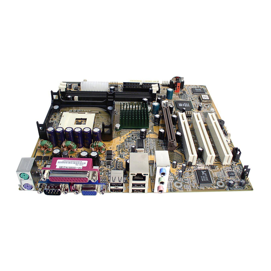
Page 21: Layout Diagram
Introduction 1-2. Layout Diagram User’s Manual... - Page 22 Chapter 1 Chapter 1 SG-72 SG-72...
-
Page 23: Chapter 2. Hardware Setup
Hardware Setup Chapter 2. Hardware Setup Before the Installation: Turn off the power supply switch (fully turn off the +5V standby power), or disconnect the power cord before installing or unplugging any connectors or add-on cards. Failing to do so may cause the motherboard components or add-on cards to malfunction or damaged. 2-1. -
Page 24: Install Pentium ® 4 Cpu And Heatsink Supporting-Base
Retention Module Base. 6. The Fan and Retention Mechanism Assembly and Retention Module Base should now firmly lock up with each other with the heatsink inside. ATTENTION: Do not forget to set the correct bus frequency and multiple for your processor. SG-72... -
Page 25: Install System Memory
Hardware Setup 2-3. Install System Memory This motherboard provides two 184-pin DDR DIMM slots for maximum memory expansion up to 2GB. Table 2-1. Valid Memory Configurations Bank Memory Module Total Memory Bank 0, 1 (DIMM1) 128, 256, 512MB, 1GB 128MB ~ 1GB Bank 2, 3 (DIMM2) 128, 256, 512MB, 1GB 128MB ~ 1GB... -
Page 26: Connectors, Headers And Switches
Failing to so may cause severe damage to your motherboard and/or peripherals. Plug in the AC power cord only after you have carefully checked everything. (1). ATX Power Input Connectors This motherboard provides two power connectors to connect to an ATX12V power supply. SG-72... -
Page 27: Fan Connectors
Hardware Setup (2). FAN Connectors These 3-pin connectors each provide power to the cooling fans installed in your system. The CPU must be kept cool by using a powerful fan with heatsink. The system is capable of monitoring the speed of the CPU fan. •... -
Page 28: Cmos Memory Clearing Header
CMOS memory, disconnect all the power cables from the motherboard and then move the jumper cap into the CLEAR setting for a few seconds. • Pin 1-2 shorted (default): Normal operation. • Pin 2-3 shorted: Clear CMOS memory. SG-72... -
Page 29: Bios Protection Header
Hardware Setup (4). BIOS Protection Header This jumper enables you to prevent the BIOS from being updated (flashed). Set the jumper to Write Protect Disabled setting if you are going to update your BIOS. After updating the BIOS, return it to the default Write Protect Enabled setting. -
Page 30: Front Panel Switches & Indicators Header
The switch should maintain contact for at least 50 ms to signal the power supply to switch on or off. The time requirement is due to internal de-bounce circuitry. After receiving a power on/off signal, at least two seconds elapses before the power supply recognizes another on/off signal. SG-72... -
Page 31: Floppy Disk Drive Connector
Hardware Setup (6). Floppy Disk Drive Connector This connector supports two standard floppy disk drives via a 34-pin 34-conductor ribbon cable. Connecting the Floppy Disk Drive Cable: 1. Install one end of the ribbon cable into the FDC1 connector. The colored edge of the ribbon cable should be aligned with pin-1 of FDC1 connector. -
Page 32: Ide Connectors
“Primary Slave”. The first drive connected to IDE2 is referred to as “Secondary Master” and the second drive as “Secondary Slave”. Keep away from connecting one legacy slow speed drive, like CD-ROM, together with another hard drive on the same IDE channel; this will drop your integral system performance. SG-72... -
Page 33: Internal Audio Connectors
Hardware Setup 2-11 (8). Internal Audio Connectors These connectors connect to the audio output of internal CD-ROM drive or add-on card. (9). Accelerated Graphics Port Slot This slot supports an optional AGP graphics card up to 4X/8X mode. ATTENTION: This motherboard does not support 3.3V AGP cards. Use only 1.5V or 0.8V AGP cards. User’s Manual... -
Page 34: Additional Usb Port Headers
Besides the onboard USB ports (USB1/USB2) at the rear edge I/O port array, you can add two additional USB ports by connecting extension cables to these headers (USB3/USB4). Pin Assignment Pin Assignment Data0 - Data1 - Data0 + Data1 + Ground Ground SG-72... -
Page 35: Additional Com2 Port Header
Hardware Setup 2-13 (11). Additional COM2 Port Header Besides the onboard serial port (COM1) at the rear edge I/O port array, you can add a second serial port by connecting a serial port extension bracket to this header. User’s Manual... -
Page 36: Front Panel Audio Connection Header
To use the audio connector at rear panel, disconnect the extension cable, attach the jumpers back at pin 5-6, and pin 9-10 (default setting). Pin Assignment Pin Assignment Audio Mic. Ground Audio Mic. Bias Speaker Out Right Speaker Out Right Channel Channel Return Speaker Out Left Speaker Out Left Channel Channel Return SG-72... -
Page 37: Chassis Speaker Connection Header
Hardware Setup 2-15 (13). Chassis Speaker Connection Header This header connects to the computer case’s built-in speaker. Pin Assignment Signal Ground User’s Manual... -
Page 38: Back Panel Connectors
Line Out: Connects to the front left and front right channel in the 5.1-channel or regular 2-channel audio system. • Mic In: Connects to the plug from external microphone. • LAN: Connects to Local Area Network. • USB1/USB2: Connects to USB devices such as scanner, digital speakers, monitor, mouse, keyboard, hub, digital camera, joystick etc. SG-72... -
Page 39: Chapter 3. Bios Setup
BIOS Setup Chapter 3. BIOS Setup This motherboard provides a programmable EEPROM that you can update the BIOS utility. The BIOS (Basic Input/Output System) is a program that deals with the basic level of communication between processor and peripherals. Use the BIOS Setup program only when installing motherboard, reconfiguring system, or prompted to “Run Setup”. -
Page 40: Standard Cmos Features
When set to [Auto], the BIOS will automatically check what kind of IDE drive you are using. If you want to define your own drive by yourself, set it to [Manual] and make sure you fully understand the meaning of the parameters. Please refer to the instruction manual provided by the device’s manufacturer to get the setting right. SG-72... - Page 41 BIOS Setup Access Mode: This item selects the mode to access your IDE devices. Leave this item to its default [Auto] setting to detect the access mode of your HDD automatically. Capacity: This item displays the approximate capacity of the disk drive. Usually the size is slightly greater than the size of a formatted disk given by a disk-checking program.
-
Page 42: Advanced Bios Features
This item is used to enable the L3 cache (default setting) and appears only for certain CPU (Intel Pentium 4 processor with HT Technology Extreme Edition) that possesses L3 cache. Hyper-Threading Technology This item is used to enable the functionality of the processor with Hyper-Threading Technology and will appear only when using such processor. SG-72... - Page 43 BIOS Setup The Hyper-Threading Technology helps your PC work more efficiently by maximizing processor resources and enabling a single processor to run two separate threads of software simultaneously, bringing forth greater performance and system responsiveness when running multiple applications at once.
-
Page 44: Advanced Chipset Features
DRAM installed. Do not change the values in this field unless you change specifications of the installed DRAM or the installed CPU. CAS Latency Time This item controls the timing delay (in clock cycles) before the DRAM starts a read command after receiving it. SG-72... - Page 45 BIOS Setup RAS Active Time (tRAS) This item allows you to set the amount of time a RAS can be kept open for multiple accesses. High figures will improve performance. RAS Precharge Time (tRP) This is the duration of the time interval during which the Row Address Strobe signal to a DRAM is held low during normal Read and Write Cycles.
-
Page 46: Integrated Peripherals
This item allows the system to be cached in memory for faster execution. Enable this item for better performance. Video RAM Cacheable: These items allow the video BIOS and RAM to be cached in memory for faster execution. Enable these items for better performance. 3-4. Integrated Peripherals SG-72... - Page 47 BIOS Setup OnChip IDE Device: Click <Enter> key to enter its submenu: Internal PCI/IDE: Use these items to enable or disable the internal PCI IDE channels that are integrated on the motherboard. IDE Bus Master: This option enables or disables the IDE bus mastering capability under the DOS environment. IDE Burst Mode: This option, when enabled will instruct the system to send every write transaction to the write buffer.
- Page 48 This option is used to assign the I/O address and interrupt request (IRQ) for onboard serial port 2 (COM2). Onboard Parallel Port: This option is used to assign the I/O address and interrupt request (IRQ) for the onboard parallel port. SG-72...
- Page 49 BIOS Setup 3-11 Parallel Port Mode: Enables you to set the data transfer protocol for your parallel port. There are four options: SPP (Standard Parallel Port), EPP (Enhanced Parallel Port), ECP (Extended Capabilities Port) and ECP+EPP. SPP allows data output only. Extended Capabilities Port (ECP) and Enhanced Parallel Port (EPP) are bi-directional modes, allowing both data input and output.
-
Page 50: Power Management Setup
If the system’s power is off when AC power failure occurs, it will remain off when power returns. If the system’s power is on when AC power failure occurs, the system will power-on when power returns. SG-72... - Page 51 BIOS Setup 3-13 PM Wakeup Events: Click <Enter> key to enter its submenu: Wakeup by Ring: An input signal on the serial Ring Indicator (RI) line (in other words, an incoming call on the modem) awakens the system from a soft off state. Wakeup by PME# of PCI: This item specifies whether the system will be awakened from power saving modes when activity or input signal of the specified hardware peripheral or component is detected.
-
Page 52: Pnp/Pci Configurations
Back to PnP/PCI Configurations Setup Menu: PCI/VGA Palette Snoop: This item determines whether the MPEG ISA/VESA VGA cards can work with PCI/VGA or not. [Enabled]: MPEG ISA/VESA VGA cards work with PCI/VGA. [Disabled]: MPEG ISA/VESA VGA cards do not work with PCI/VGA. SG-72... -
Page 53: Pc Health Status
BIOS Setup 3-15 PIRQ_0 Use IRQ No. ~ PIRQ_7 Use IRQ No.: This item specifies the IRQ number manually or automatically for the devices installed on PCI slots. 3-7. PC Health Status CPU Shutdown Temperature: This item sets the temperature that would shutdown the system automatically in order to prevent system overheats. -
Page 54: Frequency/Voltage Control
This option protects the BIOS configuration or restricts access to the computer itself. 3-12. Save & Exit Setup This option saves your selections and exits the BIOS setup menu. 3-13. Exit Without Saving This option exits the BIOS setup menu without saving any change. SG-72... -
Page 55: Chapter 4. Driver Installation
Driver Installation Chapter 4. Driver Installation All the necessary drivers are included within the Drivers & Utilities CD that came packaged with your board. The display shown in the following figure should appear after inserting this CD into your CD-ROM drive, if not, enter [My Computer] [CD-ROM] Drive double... -
Page 56: Setup Items
View the user’s manual in PDF file. • Utility Click to enter a sub-screen for installing Acrobat Reader, DirectX, and Award BIOS Flash Utility software. • Browse CD Browse the contents of this CD-ROM. • Close Exit the CD setup items. SG-72... -
Page 57: Appendix A. Troubleshooting (Need Assistance
Troubleshooting (Need Assistance?) Appendix A. Troubleshooting (Need Assistance?) Q & A: Q: Do I need to clear the CMOS before I use a new motherboard to assemble my new computer system? A: Yes, we highly recommend that you clear the CMOS before installing a new motherboard. Please move the CMOS jumper from its default 1-2 position to 2-3 for a few seconds, and then back. - Page 58 Sound Card Driver. Write down the Sound Card model, motherboard model, BIOS identification number on the technical support file (refer to main instructions), and describe the problem in the space provided. We will show you how to fill the “Technical Support Form”. SG-72...
- Page 59 To fill in this “Technical Support Form”, refer to the step-by-step instructions given below: . MODEL: Note the model number given in your user’s manual. Example: SG-72 . Motherboard model number (REV): Note the motherboard model number labeled on the motherboard as “REV:*.**”.
-
Page 60: Technical Support Form
Appendix A Technical Support Form Company Name: Phone Number: Contact Person: Fax Number: E-mail Address: Model BIOS ID # Motherboard Model No. DRIVER REV OS/Application Hardware Name Brand Specifications IDE1 IDE2 IDE1 CD-ROM-Drive IDE2 System Memory ADD-ON CARD Problem Description: SG-72... -
Page 61: Appendix B. How To Get Technical Support
Also please make sure you have the latest drivers from your peripheral cards makers! 3. Check the ABIT Technical Terms Guide and FAQ on our Website. We are trying to expand and make the FAQs more helpful and information rich. Let us know if you have any suggestions. - Page 62 They should have reasonable return or refund policies. How they serve you is also a good reference for your next purchase. 6. Contacting ABIT. If you feel that you need to contact ABIT directly you can send email to the ABIT technical support department. First, please contact the support team for the branch office closest to you.
- Page 63 How to Get Technical Support North America and South America: Japan: ABIT Computer (U.S.A.) Corporation ABIT Computer (Japan) Co. Ltd. 45531 Northport Loop West, Fax: 81-3-5396-5110 Fremont, California 94538, U.S.A. http://www.abit4u.jp Tel: 1-510-623-0500 Fax: 1-510-623-1092 Shanghai: sales@abit-usa.com ABIT Computer (Shanghai) Co. Ltd.
- Page 64 Please contact the reseller from whom you bought the product. You should be able to get RMA service there. 8. Reporting Compatibility Problems to ABIT. Because of tremendous number of email messages we receive every day, we are forced to give greater weight to certain types of messages than to others.
Need help?
Do you have a question about the SG-72 and is the answer not in the manual?
Questions and answers