HP BladeSystem c7000 Setup And Installation Manual
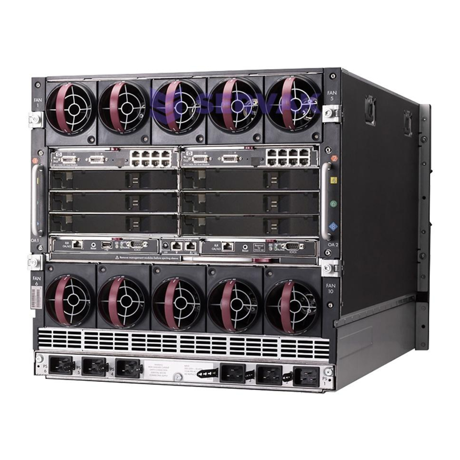
Bladesystem c7000 carrier-grade enclosure
Hide thumbs
Also See for BladeSystem c7000:
- Setup and installation manual (103 pages) ,
- Maintenance and service manual (80 pages) ,
- Quickspecs (43 pages)

Related Manuals for HP BladeSystem c7000


Summary of Contents for HP BladeSystem c7000
- Page 1 HP BladeSystem c7000 Carrier-Grade Enclosure Setup and Installation Guide Abstract This document contains specific information that is intended for users of this HP product. HP Part Number: 5900-2654 Published: February 2013 Edition: 3...
- Page 2 © Copyright 2007 – 2013 Hewlett-Packard Development Company, L.P. The information contained herein is subject to change without notice. The only warranties for HP products and services are set forth in the express warranty statements accompanying such products and services. Nothing herein should be construed as constituting an additional warranty. HP shall not be liable for technical or editorial errors or omissions contained herein.
-
Page 3: Table Of Contents
Contents 1 Overview....................6 This manual supplements other manuals..................6 HP BladeSystem c7000 Carrier-Grade Enclosure................6 HP BladeSystem c7000 Carrier-Grade Enclosure components............6 Seismic rack..........................6 Seismic rack components......................6 Seismic rack options......................7 Rackable elements.......................7 2 Component and LED identification..............8 Full-height Device Bay numbering....................8 Half-height Device Bay numbering....................8 DC Input Module components....................9... - Page 4 Installing the breaker panel brackets................37 Installing the breaker panel into the rack................37 DC Input Module.......................37 DC Power Supply.......................38 HP Seismic Rack Mounting Kit for the MSA2324 CG..............38 5 Cabling and powering the enclosure............42 Cabling the enclosure......................42 Cabling the DC input module....................42 Cabling the Breaker Panel.......................44...
- Page 5 Typographic conventions......................64 A Alternate-sized site cables.................66 Required documentation......................66 Recommended site power cables....................66 Recommended grounding cables....................66 Requirements for using alternate-sized site power or ground cables..........66 B Acronyms and abbreviations..............68 Index......................69 Contents...
-
Page 6: Overview
In this document, the word “rack” and “cabinet” are used interchangeably. There are now two versions of racks for seismic systems: the original seismic rack and seismic rack R2. The original seismic rack has a rectangular HP logo. The seismic rack R2 is black and has a round HP logo. -
Page 7: Seismic Rack Options
Seismic rack options In addition to the standard racks, HP also provides rack options to complement or complete your rack solution. Some of these options are necessary for full NEBS compliance. Part Number (Seismic Rack Option Name Product Number Part Number (Seismic Rack) -
Page 8: Component And Led Identification
2 Component and LED identification Full-height Device Bay numbering Half-height Device Bay numbering Component and LED identification... -
Page 9: Dc Input Module Components
DC Input Module components Terminal block Ground stud (4x) Case screw (4x) -48V (Power) Captive screw (3x) RTN (Return) Terminal block numbering Power Supply Bay numbering DC Input Module components... -
Page 10: Power Supply Leds
Power Supply LEDs Power LED 1 (green) Fault LED 2 (amber) Condition Power supply DC output on and OK DC present/standby output on Power supply failure No DC power to power supply Component and LED identification... -
Page 11: Site Preparation Guidelines
System cabling Power and I/O cables can enter the server from either the top or the bottom of the cabinets, depending on how the cabinets are ordered from HP and the routing of the power feeds at the site: Cabinets are optimized for top-down cabling. -
Page 12: Cooling Airflow Direction
These requirements must be investigated by the customer or the customer’s installation provider. The customer assumes all risk in using the seismic rack on a raised floor. For your site’s floor system, consult with your HP site preparation specialist or an appropriate floor system engineer. -
Page 13: Operational Space
These requirements provide reasonable protection against interference with radio and television communications. Installing and using the system in strict accordance with HP instructions minimizes the chances that the system will cause radio or television interference. However, HP does not guarantee that the system will not interfere with radio and television reception. -
Page 14: Electrostatic Discharge
Ensure that all cable connector screws are firmly tightened. Use only HP supported peripheral devices. Ensure that all panels and cover plates are in place and secure before system operation. Electrostatic discharge Preventing electrostatic discharge To prevent damaging the system, be aware of the precautions you must follow to set up the system or handle parts. -
Page 15: Installation
The HP BladeSystem c7000 Carrier-Grade Enclosure is intended for installation into a Central Office or similar telecommunications environment. The HP DC Power Supply, cable management system, and seismic brace are intended for use in the HP BladeSystem c7000 Enclosure and HP Carrier-Grade rack. -
Page 16: Marking The Position Of The Anchor Holes
Safety goggles Ear plugs or other ear protection Rubber bulb (ear syringe available from any pharmacy) Try square Standard screw driver #2 Phillips screwdriver 3/4 inch hammer drill (Hilti Model No. TE10, TE12S, TE52 or equivalent) 18 mm (3/4 inch) high-speed drill bit (Hilti part number TC-F- 1 8/34 or equivalent) For seismic rack: ◦... -
Page 17: Preparing The Rack Floor Anchors
Load the drill bit: Unlock the chuck on the rotary hammer drill. Insert the concrete drill bit in the chuck. Lock the chuck. Set the depth gauge on the hammer drill for 102 mm (4 inches). M12 anchor hole depth must be 102 mm (4 in.) Move the side handle of the hammer drill to a convenient position and tighten in a clockwise direction. -
Page 18: Removing The Rack Door
Using heavy-freight-handling equipment, move the shipping pallet as close as possible to the planned installation area. Unscrew the screws in the base. Unfasten the metal clips and dispose of them. Remove the side and top panels. Removing the rack door To provide access to all sides of the rack while you are installing the various components, first remove the rack doors. -
Page 19: Removing The Side Panels
For the seismic rack: Pull down on the spring-loaded handles on the hinge assembly at the top of the door so that the small pin securing the door to the hinge retracts. Move the top of the door away from the rack so that the spring-loaded pin is free of the hinge assembly. -
Page 20: Removing The Kickplate
Removing the kickplate Remove the kickplates from the front and rear base of the rack to access the rack anchor bolts. To remove a kickplate: For the seismic rack: Turn the quarter-turn fasteners securing the kickplate. Pull the kickplate away from the base of the rack. For the seismic rack R2: Use a T30 torx screwdriver to unscrew the six screws securing the kickplate. -
Page 21: Moving The Seismic Rack Off The Pallet
• For the seismic rack: Using a 9/16-inch socket and 1/2-inch ratchet, unscrew the eight screws (four on each side of the rack) securing the rack to the pallet. The screws are located next to the rack leveling pads. For the seismic rack R2: Using a 17-mm socket wrench, unscrew the four bolts securing the rack to the pallet. - Page 22 NOTE: For sites that are not equipped with overhead hoists, installing casters onto the racks is required to move the racks off the pallets or around the room. The casters are designed for short-distance moves over a smooth, hard surface or short-pile carpeting. Using the caster kit items and the rack rail, add four casters to the bottom of the rack frame: For the seismic rack: Retrieve the appropriate caster unit (left or right) from the caster kit:...
- Page 23 10. Using the 3/4-inch wrench, raise the rack on the casters by turning the caster jack screws clockwise, a little at a time, until the rack is high enough above the pallet to allow you to slide the pallet out from under it. WARNING! Do not raise the rack more than necessary.
- Page 24 Installation...
-
Page 25: Positioning The Seismic Rack
Install caster wheel and thread block into caster arm using two hexhead bolts. WARNING! When moving the cabinet with the casters installed, the cabinet must be raised no higher than two inches from the floor to maintain stability. When transferring cabinet between casters and pallet, the caster legs should be raised/lowered in unison to maintain stability. -
Page 26: Removing The Casters
Ensure the eight leveling feet are as high as they will go. They should be shipped from the factory in the fully raised position. If necessary, adjust them using a 5/16 inch Allen key wrench. Roll the rack into position over the drilled holes for the rack. Align the base of the racks with the chalk line and anchor hole locations and ensure that the rack location in the lineup is correct with respect to the floor plan drawings. - Page 27 For the seismic rack only: Place the anchor rod assembly and washer kit into the anchor holes. Figure 1 (page 27) for proper stackup. For the seismic rack R2 only: Place the concrete anchor bolt with washer kit into the anchor holes.
-
Page 28: Bolting The Seismic Rack To A Raised Floor
These requirements must be investigated by the customer or the customer’s installation provider. The customer assumes all risk in using the seismic rack on a raised floor. For your site’s floor system, consult with your HP site preparation specialist or an appropriate floor system engineer. -
Page 29: Join Adjacent Cabinets Together (Optional)
Figure 2 Anchor Rod Assembly For Raised Floor Socket head bolt cap Raised floor Spring washer Saddle nut Flat washer Raised floor channel Nylon bushing Concrete floor Drip plate (included in rack Access floor pedestal accessory kit) Rack leveling foot Rack base Thread the saddle nut onto the bottom of the bolt and drop the saddle nut into the site’s u-channel under the raised floor. - Page 30 To join two cabinets together, you need two brackets, 12 round washers, and four 5/8-inch bolts. Cabinets are joined at the top at two anchor positions. For each anchor position: For the seismic rack: For information on how to orient the bracket when connecting a seismic rack to other seismic racks, see Figure 3 (page 30).
-
Page 31: Enclosure Installation
Install the heaviest item first, and continue to populate the rack from the bottom to the top. IMPORTANT: Install all cage nuts for the enclosure, seismic brace, and cable management system before installing the enclosure. Cage nuts can not be installed post-installation of a c7000 CG enclosure. NOTE: The following procedures are for installing a c7000 Carrier-Grade enclosure into the center of the rack. -
Page 32: Rack Mount Bracket Installation
Rack mount bracket installation Use a Torx screwdriver to screw the rack mount brackets into the top and middle holes of U1 and U2 (U12 and U13). Install one cage nut into the top hole of U4 and the middle hole of U9 (U15 and U20) in the front mounting rails. -
Page 33: Cable Management System Installation
Cable management system installation Install one cage nut into the bottom holes of U5 or U9 (U16 and U20) in the rear mounting rails. Attach the cable management system to each rear rail, making sure to attach it to the cage nut. -
Page 34: Hp Bladesystem Cable Management Tray Installation
HP BladeSystem Cable Management Tray installation The HP BladeSystem Cable Management Tray enables you to pass cables from the front of the enclosure through the tray to the back of the rack. If you do not install the cable management tray, you must still reserve 2U of space for the cable management tray before installing the second enclosure. -
Page 35: Component Installation
Secure the rail bracket to the rack with the screws provided. Align the cable management tray with the end of the rail brackets. Slide the tray into the brackets until it reaches the back of the rack. TIP: If you have any difficulty sliding the cable management tray into the rail brackets, loosen the screws that hold the rail bracket to the rack while sliding the tray in. -
Page 36: Breaker Panel
Component Location U position First (lower) seismic brace (1U total) Above the first enclosure U1 1 First (lower) enclosure (10U total) Bottom of the seismic rack U1–U10 Item Description First enclosure Seismic brace Cable management tray Second enclosure Seismic brace Cable management tray Second (lower) breaker panel First (upper) breaker panel... -
Page 37: Installing The Sheet Metal Grommet
Installing the sheet metal grommet The sheet metal grommet protects the cables that run through the opening on the top of the rack. From the rear of the rack, unscrew the two top plate nuts, and then remove the rack top. Discard the plate and nuts. -
Page 38: Dc Power Supply
Six power supplies: All bays Install power supply blanks in any unused power supply bays. To install a power supply: Slide the HP BladeSystem Insight Display to the right or left to gain access to all power supply bays. Open the power supply bracket. - Page 39 Attach the single-hole ground cable lug between the front right mounting ear (top hole) and the rack with a lock washer and screw. HP Seismic Rack Mounting Kit for the MSA2324 CG...
- Page 40 Item Description Lock washer Screw Flat washer Bolt Ground cable lug. Position between ear and rail (cable not shown) Loosely attach the rear brackets to the rear bracket assemblies. Attach the loose end of the ground cable to the front rack ground rail. Installation...
- Page 41 10. Verify that the MSA2324 CG is evenly spaced between the right and left rack rails, and then tighten the front and rear bracket screws. HP Seismic Rack Mounting Kit for the MSA2324 CG...
-
Page 42: Cabling And Powering The Enclosure
5 Cabling and powering the enclosure Cabling the enclosure After all system hardware is installed, cable the components. See the HP ProLiant BladeSystem c-Class Site Planning Guide on the Documentation CD or the HP website (http://www.hp.com) for additional cabling and site planning requirements. - Page 43 Item Description DC module cover DC cover screw (4x) -48V (power) To correctly use separate conductors, you must size the conductor to handle any fault current up to the limit of the circuit protection device feeding power to the equipment bay. You must connect any conductor that is #6 AWG or larger using a listed two-hole compression type connector per GR- 1 089, R9-25 and TR-295.
-
Page 44: Cabling The Breaker Panel
Complete the connections to the outer DC input module connections and then move to the middle. Place star washers on the DC input module connections. Place the two-hole lug on the DC input module connections, and then secure the lug with a lock washer and nut, observing the markings on the on the DC input module for the -48VDC and RTN locations. -
Page 45: Installing Breaker Panel Site Input Power Cables
Installing Breaker Panel site input power cables WARNING! A qualified electrician must determine the cabling requirements for the input power of the breaker panel. You must verify that the correct size cables are installed into side A and side B of the breaker panel. WARNING! You must disconnect the input cables from the site power or battery before connecting the breaker panel input cables. -
Page 46: Connecting The Breaker Panel To The Power Supplies
Connecting the Breaker Panel to the power supplies The HP BladeSystem Breaker Panel contains six red source -48 DC volt cables and six black return cables. The ends of each cable are labeled with the location, which describe where to connect the cable to the breaker panel and to the DC input module. - Page 47 Cable Breaker Panel End (90° Lug) Input Module End (45° Lug) Red source -48 DC or Black return BP-B2 BP-B2 (E-PS5) (E-PS5) Red source -48 DC or Black return BP-B3 BP-B3 (E-PS6) (E-PS6) Use the following DC cable connection configuration table to connect the DC power cables to the breaker panel and to the DC input module.
-
Page 48: Cable Management
Cable management CAUTION: Gigabit Ethernet ports (intrabuilding ports) of the HP BladeSystem c7000 Carrier-Grade system require the use of shielded Cat5e cables grounded at both ends. The intrabuilding ports of the equipment are suitable for connection only to intrabuilding, unexposed wiring, or cabling. Do not connect the intrabuilding ports of the equipment metallically to interfaces that connect to the outside plant or its wiring. -
Page 49: Securing Cables
Item Description U14.5 U14.5 Route signal and power cables through the top of the rack, directly above the signal and power routing areas. Route left cables out of the top left of the rack. Route right cables out of the top right of the rack. - Page 50 Unscrew and remove each guide. Install a wire tie for copper wire or a hook-and-loop strap for fiber cable. Ties or fasteners cannot exceed 1.3 cm (0.5 in) wide or 12.7 cm (5.0 in) long. Cabling and powering the enclosure...
-
Page 51: Cable Repair
Secure each guide to the cable management system frame. You can also use hook-and-loop straps to fasten cables to the rack. Cable repair If there is fiber cable that is not easily removed from the system: Disconnect both of the cable ends and cut cable several inches away from each connector Route new cable over the top of the old fiber cable, observing all routing rules in “Cabling the enclosure”... -
Page 52: Powering The Enclosure
Powering the enclosure Grounding the rack Intracabinet grounding for Seismic Racks Each seismic rack has two grounding rails at the rear of the cabinet in front of the mounting rails. Grounding rails are covered by metal foil in the seismic rack and conductive paint in the R2 rack. Ground cables are green with a yellow stripe and are used to connect an enclosure to the cabinet grounding rail. -
Page 53: Enclosure To Rack
of the rack (front and rear). Site ground can also be connected to the vertical grounding rails in the front and rear of the rack. Each location is designated with the following ground symbol: ai046 For the seismic rack: Connecting to each of the locations follows the same process: Using two self-tapping hex-head screws and two M6 star washers (all provided with the rack), secure the site ground lug (not provided) to the rack. -
Page 54: Module To Rack
Using the green hex screws in the rack hardware kit, attach the other end of the harness to the rack ground rail. Tighten the hex screw to 40 in-lb (4.5 Nm). Module to rack Modules with two power connections have the power connected to the left power rail and right power rail, as viewed from the rear. - Page 55 Remove the DC input module cover. Locate the grounding studs in the right and left corners of the module. Remove the nuts from the grounding studs using a 3/8-inch socket. Place star washers on the DC input module ground connections. Place the 4 AWG grounding harness on the ground connections, and secure it to the input module with a two-hole lug.
-
Page 56: Grounding The Breaker Panel
Tighten the hex screws to 40 in-lb (4.5 Nm). Grounding the breaker panel Item Description Breaker Panel Double-hole Lug with Nuts Single-hole Lug and Self-threading Screw Ground Rail To ground the breaker panel: Remove the breaker panel rear cover to expose the grounding studs common to the breaker panel. - Page 57 Route the grounding cable, and connect the single-hole lug of the grounding cable to the ground rail. Install a star lock washer between the ground rail and the lug using an M6x16mm, self-threading screw. Powering the enclosure...
-
Page 58: Troubleshooting
To obtain the guide, refer to any of the following sources and then select the HP ProLiant Servers Troubleshooting Guide: The server-specific Documentation CD The Business Support Center on the HP website: http://www.hp.com/go/bizsupport. -
Page 59: Warnings And Cautions
Insight display errors NOTE: This guide only covers Insight Display errors regarding the power supply. Refer to HP BladeSystem c7000 Enclosure Setup and Installation Guide for more Insight Display errors at start-up. -
Page 60: Power Errors
Power errors Power errors can occur because of insufficient power to an enclosure. Power errors can occur on server blades, storage blades, or interconnect modules. To correct a power error: Use the arrow buttons to navigate to Fix This, and press OK. Review and complete the corrective action suggested by the Insight Display. -
Page 61: Specifications
7 Specifications Environmental specifications Specification Value Temperature range Operating 5°C to 40°C (41°F to 104°F) Non operating -30°C to 60°C (-22°F to 140°F) Short-term -5°C to 50°C (23°F to 122°F) Wet bulb temperature Operating 28ºC (82.4ºF) Non operating 38.7ºC (101.7ºF) Relative humidity (noncondensing) Operating 20% to 80%... -
Page 62: Enclosure Specifications
Unpacking area: When moving the cabinet off the shipping pallet, you need approximately 9 feet (2.74 meters) on one side of the cabinet to allow you to slide the pallet out from under the cabinet after the cabinet has been raised on the casters. Enclosure specifications Specification Value... -
Page 63: Support And Other Resources
(http://welcome.hp.com/country/ us/en/wwcontact.html.) In other locations, see the Contact HP worldwide (in English) webpage: http://welcome.hp.com/country/us/en/wwcontact.html. For HP technical support: In the United States, for contact options see the Contact HP United States webpage: (http:// welcome.hp.com/country/us/en/contact_us.html) To contact HP by phone: ◦... -
Page 64: Installing Hp Insight Remote Support Software
HP strongly recommends that you install HP Insight Remote Support software to complete the installation or upgrade of your product and to enable improved delivery of your HP Warranty, HP Care Pack Service or HP contractual support agreement. HP Insight Remote Support supplements... - Page 65 NOTE: A note contains additional information to emphasize or supplement important points of the main text. Typographic conventions...
-
Page 66: A Alternate-Sized Site Cables
This appendix provides information for customers who plan to use alternate-sized site power input cables and lugs to connect site power. The alternate-sized cables and lugs must be provided by the customer or the installation provider for the customer. HP does not provide these items to the customer. - Page 67 NEBS 40°C environment. NOTE: Alternate-sized cables and lugs must be provided by the customer or the customer’s installation provider. HP does not provide these items to the customer. Requirements for using alternate-sized site power or ground cables...
-
Page 68: B Acronyms And Abbreviations
B Acronyms and abbreviations American Wire Gauge Canadian Standards Association electrostatic discharge Federal Communications Commission International Electrotechnical Commission NEMA National Electrical Manufacturers Association NFPA National Fire Protection Association network interface controller NEBS Network Equipment–Building system power distribution unit serial attached SCSI unit identification unshielded twisted-pair Acronyms and abbreviations... -
Page 69: Index
DC Input Module rack, installation, rack mount brackets document installation, related documentation, Raised floors, requirements for, documentation Receiving and unpacking, HP website, related documentation, Dust and microscopic particles, safety information, Electrostatic discharge, warnings and cautions, enclosure seismic brace cabling, installation,... - Page 70 websites product manuals, Weight calculation, Zinc, cadmium, or tin particulates, Index...
Need help?
Do you have a question about the BladeSystem c7000 and is the answer not in the manual?
Questions and answers