Advertisement
Table of Contents
- 1 Features
- 2 Startup
- 3 Fan Switch
- 4 Current Set Temperature/Setting New Temperature
- 5 Filter Monitor/Span Setting
- 6 Operation
- 7 Installation
- 8 Mount Wallplate and Thermostat
- 9 Connect Wires and Mount Thermostat to Wallplate
- 10 Xno Connection
- 11 Wiring Diagrams
- 12 Troubleshooting
- Download this manual
Digital Thermostat
Owners Manual
Mode:CP1717
Your new thermostat will provide years of reliable service. Using this digital thermostat will provide more uniform comfort in your home through
the seasons. Thank you for buying the product!
Please read this manual for complete instructions on installing and operating your thermostat. If you require further assistance, please feel free to contact us.
IMPORTANT INFORMATION
1. This thermostat is designed to work on the following systems:
Ÿ Gas – Standing Pilot
Ÿ Gas – Electronic Ignition
Ÿ Gas – Fired Boilers
Ÿ Gas – Milivolt Systems
Ÿ Oil – Fired Boilers
This thermostat will NOT control multistage heat pumps or 110/220V baseboard electric heating systems.
2. Temperature Range
This thermostat can be set between 45˚F and 95˚F (7˚C and 35˚C). However, it will display room temperatures from 30˚F to 99˚F (0˚C and 37˚C). "HI" will be displayed
if the temperature is higher than 99˚F (37˚C), and "LO" will be displayed if the temperature is lower than 30˚F (0˚C).
This thermostat will automatically cutoff in Heat mode if the temperature rises above 95˚F (35˚C), and automatically cutoff in Cool mode if the temperature drops below
45˚F (7˚C).
3. Compressor Protection
This thermostat provides a 4 minute delay after shutting off the compressor before it can be restarted. This feature will prevent damage to your compressor caused by
rapid cycling. It does not prevent a rapid compressor restart due to short power outages.
4. Battery Warning
Two fresh AA alkaline batteries should provide well over one year of service. However, when the batteries become drained the Low Battery Indicator will flash on the
display. When this message occurs, install new alkaline batteries. You have approximately 1 minute to change the batteries and keep the thermostat's settings. Once
the batteries have become too low to ensure proper operation, your system will be turned off, and the display will be cleared except for flashing Low Battery Indicator
on the LCD display.
CAUTION: When only the battery icon flashes on the display, the thermostat is shut down, and your system will no longer operate. In this condition, there is no
temperature control of your dwelling.
NOTE: The backlight will not function when the thermostat is in low battery condition.
NOTE: If you plan to be away from the premises over 30 days, we recommend that you replace the old batteries with new alkaline batteries prior to leaving.
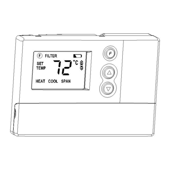
FEATURES
Structure of thermostat and explanation for the keypads
Ÿ Oil – Fired Furnace
Ÿ Single Stage Heat Pumps – with no
auxiliary heat
Ÿ Electric Furnace
Ÿ Electric Air Conditioning
Advertisement
Table of Contents

Related Manuals for Comfort Stat CP1717


Summary of Contents for Comfort Stat CP1717
-
Page 1: Features
Digital Thermostat Owners Manual Mode:CP1717 Your new thermostat will provide years of reliable service. Using this digital thermostat will provide more uniform comfort in your home through the seasons. Thank you for buying the product! Please read this manual for complete instructions on installing and operating your thermostat. If you require further assistance, please feel free to contact us. IMPORTANT INFORMATION 1. This thermostat is designed to work on the following systems: Ÿ Gas – Standing Pilot Ÿ Oil – Fired Furnace Ÿ Gas – Electronic Ignition Ÿ Single Stage Heat Pumps – with no Ÿ Gas – Fired Boilers auxiliary heat Ÿ Gas – Milivolt Systems Ÿ Electric Furnace Ÿ Oil – Fired Boilers Ÿ Electric Air Conditioning This thermostat will NOT control multistage heat pumps or 110/220V baseboard electric heating systems. 2. Temperature Range This thermostat can be set between 45˚F and 95˚F (7˚C and 35˚C). However, it will display room temperatures from 30˚F to 99˚F (0˚C and 37˚C). “HI” will be displayed if the temperature is higher than 99˚F (37˚C), and “LO” will be displayed if the temperature is lower than 30˚F (0˚C). This thermostat will automatically cutoff in Heat mode if the temperature rises above 95˚F (35˚C), and automatically cutoff in Cool mode if the temperature drops below 45˚F (7˚C). 3. Compressor Protection This thermostat provides a 4 minute delay after shutting off the compressor before it can be restarted. This feature will prevent damage to your compressor caused by rapid cycling. It does not prevent a rapid compressor restart due to short power outages. 4. Battery Warning Two fresh AA alkaline batteries should provide well over one year of service. However, when the batteries become drained the Low Battery Indicator will flash on the display. When this message occurs, install new alkaline batteries. You have approximately 1 minute to change the batteries and keep the thermostat’s settings. Once the batteries have become too low to ensure proper operation, your system will be turned off, and the display will be cleared except for flashing Low Battery Indicator on the LCD display. CAUTION: When only the battery icon flashes on the display, the thermostat is shut down, and your system will no longer operate. In this condition, there is no ... -
Page 2: Startup
LCD Display: Shows Room Light:Backlight Low Battery Temperature,Set display Indicator: Filter Change Front Door: Temperature,and automatically Flashes when Indicator:Flashes Battery cover other feature with each key batteries need when filter needs Open with one information as press for easy to be replaced. to be checked. finger from top. required. viewing. Filter Key: Resets the filter change counter to zero. Up and Down Keys: System Keys for changing Switch: the Temperature Selector setting. Also used switch for for adjusting the Heat,Cool, Span. ... -
Page 3: Installation
When batteries are installed in the thermostat, the Span is reset back to setting 2. Backlighting Your thermostat has an electroluminescent lamp that backlights the display for easy viewing in the dark. When any key is pressed, the display is illuminated. The display will remain illuminated for 7 seconds after the last key is pressed. This allows the light to stay on if you need to operate several keys. Note: If the thermostat is in Low Battery warning condition, the backlight will not operate. Replace with 2 new AA alkaline batteries to restore the Backlight function. Low Battery Warning Your thermostat has a twostage lower battery warning system. When the batteries are first detected to be weak, the first stage low battery warning is indicated by battery symbol flashing on the LCD display. At your earliest convenience, you need to replace the batteries with 2 new AA alkaline batteries. When ... -
Page 4: Mount Wallplate And Thermostat
Figure 1 Wiring Labeling Ÿ Each wire coming from the wall to the existing thermostat is connected to a terminal point on that thermostat. Each of these terminal points is usually marked with a code latter as shown in Table A below. Ÿ Note that this thermostat has multiple function terminals that allow SingleStage Heat Pump capability. Standard systems use: Rh, Rc, G, Y, W. [SingleStage Heat Pumps use: R, Y, G, and O or B.] Table A below shows the multiple functions of the terminals. Use the terminals that match your system. Ÿ The number of wires in your system can be as few as two (for heat only systems), as many as eight, or any number in between. If you follow the labeling procedures correctly, you do not have to be concerned about how many wires there are. Ÿ There is often no terminal marking on the existing thermostat of two wire, heat only systems. Just connect either of the wires to the RH terminal, then connect the other wire to the W terminal to complete the circuit. Ÿ IMPORTANT! BEFORE DISCONNECTING ANY WIRES, APPLY THE SELFADHESIVE LABELS PROVIDED TO THE WIRE AS SHOWN IN TABLE A BELOW. (For example, attach the label marked W to the wire that toes to the W or H terminal on your existing thermostat.) IGNORE THE COLOR OF THE WIRES since these do not always comply with the standard. Ÿ After labeling wires, disconnect them from the existing thermostat. Ÿ Remove existing wallplate. To make sure wires do not fall back into wall opening, you may want to tape them to the wall. Ÿ If hole in wall is larger than necessary for wires, seal this hole with insulating material so that no hot or cold air can enter the back of the thermostat from the wall. This air could cause a false thermostat reading. Table A If the code letter on then mark the wire and connect to your existing ... -
Page 5: Connect Wires And Mount Thermostat To Wallplate
Figure 2 Ÿ Position wallplate on wall and pull existing wires through large opening. Then level for appearance. Mark holes for plastic anchors provided, if your existing holes do not line up with those on the wallplate. Ÿ Drill holes with 3/16” bit and gently tap anchors into the holes until flush with wall. Ÿ Reposition wallplate to wall, pulling wires through large opening. Insert mounting screws provided into wall anchor and tighten. See Figure 3. R Figure 3 NOTE: 5 Wire Systems If your thermostat has one wire marked R or Rh (2, 3, or 4wire system), then leave the jumper wire between the Rh and Rc terminals on the wallplate. Otherwise, if you have separate Rh and Rc wires (5wire system), then remove the jumper wire between the Rh and Rc terminals. Connect Wires and Mount Thermostat to wallplate Ÿ Match and connect the labeled wires to the appropriate coded terminal screws on the wallplate. (See Figure 4, 5.) Ignore any wires which may be present, but which were note connected to the old thermostat. Figure 4 Figure 5 Ÿ Refer to the Wiring Diagrams below to be sure your system is wired correctly. Ÿ If your system is a single stage heat pump and uses an O or B wire, you must move the System Selector switch inside the thermostat to the Heat Pump position. If you have a normal furnace or electric system, leave the switch in the Standard position. Refer to the System Selector section on the back for more information on this switch. Ÿ Be sure to tighten the terminal screws securely, otherwise a loose wire could cause operational problems with your system or thermostat. Ÿ Push excess wire back into the hole to prevent interference when installing the thermostat to the wallplate. Ÿ Make sure the System Switch is set to OFF, and the Fan Switch is set to AUTO. ... -
Page 6: Xno Connection
ŸInsert the tabs on top of the thermostat body into the slots at the top of the wallplate. Press the bottom of the thermostat body into the snap on the bottom of the wallplate. Refer to Figure 2. (NOTE: Do not force the thermostat onto the wallplate, as the terminal pins may be damaged. If it does not snap properly, the thermostat may not work.) Ÿ Insert the two AA size alkaline batteries, observing the polarity marked inside the battery compartment. Ÿ Switch on the main power at the panel or furnace. Wiring Diagrams 4Wire Heat/Cool System System STD Wallplate Jumper Selector Terminals HP R G W Y Rh/B Rc/O Fan Heat Relay Cool Heat/Cool Relay or Valve Contactor 24V Supply 5Wire/Heat Cool System System STD Wallplate ... -
Page 7: Troubleshooting
The factory position for this switch is in the STD position. Leave it in this position if you have ANY system that uses gas, oil, electric, or hot water heating. If you have a singlestage Heat Pump (no auxiliary or emergency heat source), then slide the switch to the HP position. Be sure the reversing valve wire is connected to the correct terminal for your heat pump (Rc/O) or (Rh/B). Ÿ F˚ / C˚ selector (Fahrenheit / Celsius) Your thermostat is set for F˚ mode from the factory. In order to change to C˚ mode, slide the switch to C˚ and hold any key about 2 seconds without the battery, then place the battery again. NOTE: Unless press any key about 2 seconds without the battery, then place the battery again. Te mp era tur e Di spla y JP 2 S ystem S e lecto r FA HRE NHE IT CE NTIG RA DE S TD HP K3 HG F an Op tion HE ...
Need help?
Do you have a question about the CP1717 and is the answer not in the manual?
Questions and answers