Table of Contents
Advertisement
Quick Links
- 1 Auto Glide Key Pad Installation
- 2 Auto Glide Mechanical Installation
- 3 Auto Glide Control Box Installation
- 4 Auto Glide Control Box Harnesses Overview
- 5 Auto Glide Electrical Installation
- 6 Auto Glide Control Box Harness Installation
- 7 Auto Glide Test Mode
- Download this manual
See also:
Owner's Manual
TM
TM
Auto Glide
Auto Glide
Boat Control System
Boat Control System
Owner's Manual A
Owner's Manual A
Installation & Setup
Installation & Setup
Procedures
Procedures
Please visit our website to view up-to-date information and various
videos which may be beneficial to you. www.lencoautoglide.com
3-10-11
Advertisement
Table of Contents

Related Manuals for LENCO Auto Glide

Summary of Contents for LENCO Auto Glide
- Page 1 Auto Glide Auto Glide Boat Control System Boat Control System Owner’s Manual A Owner’s Manual A Installation & Setup Installation & Setup Procedures Procedures Please visit our website to view up-to-date information and various videos which may be beneficial to you. www.lencoautoglide.com...
-
Page 2: Table Of Contents
2.2 Replacing Existing 123 LED Indicator / 124 Standard Key Pad ...5 ...6 2.3 Auto Glide Control Box Installation ...6 2.4 Optional Auto Glide Control Box Mounting Bracket Installation 2.5 Replacing Existing 123 / 123DR LED Indicator / 124 Standard Control Box ...6 ...7-11 AUTO GLIDE ELECTRICAL INSTALLATION ...7... -
Page 3: Product Overview
CONGRATULATIONS! You have just purchased the most advanced automatic trim tab control system. Welcome to the future! The Auto Glide Boat Control System is the first genuine fully automatic trim tab control system in the world. The Auto Glide System uses unsurpassed technology to monitor the boats speed and position, and automatically adjusts the trim tabs position to accommodate any boating condition to provide a smoother, more comfortable ride. -
Page 4: System Requirements
1.0 PRODUCT OVERVIEW WARNING CAUTION CAUTION IMPORTANT INSTRUCTIONS AND FACTS ABOUT YOUR NEW AUTO GLIDE BOAT CONTROL SYSTEM ** PLEASE READ ALL OF THE INSTALLATION INSTRUCTIONS IN THIS MANUAL BEFORE PROCEEDING. YOU WILL NEED TO PRINT OUT YOUR APPLICABLE WIRING SCHEMATIC / DRAWING / PARTS LIST FROM OUR WEBSITE BEFORE YOU BEGIN THE INSTALLATION PROCESS. -
Page 5: Auto Glide Mechanical Installation
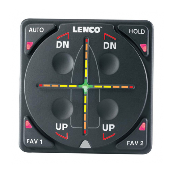
From the top side of the helm, remove existing key pad. Install the Auto Glide key pad by simply dropping it into the existing 2” (5.08cm) hole and screw the large white key pad nut onto the back of the key pad. Make sure the key pad is securely installed. -
Page 6: Auto Glide Control Box Installation
- Install level. A 15 (+/-) tolerance in all directions is allowed. (See Figure 2.3.1) - Install within 4’ (1.21m) of the Auto Glide Key Pad. (If key pad must be installed further than 4’ use a CANBUS Extension Cable 30260-XXX Series. See price list for different lengths.) - Control box mounting hardware to be supplied by customer. -
Page 7: Auto Glide Electrical Installation
- Dual Actuator Auto Glide Control Box Harness for systems with four actuators (See Figure 3.1.2) Each Auto Glide Control Box Harness has 6 sets of electrical connections coming out of the 30 pin Cinch connector. Single Actuator Control Box Harness Figure 3.1.1... -
Page 8: Auto Glide Control Box Harness Installation
If your Lenco Trim Tab system is OEM - wired with a power harness, simply connect to the wires as shown in your drawing. If you must run power to the system, you should purchase a power pigtail to plug into the Auto Glide main harness and complete the wiring installation. -
Page 9: Battery Switch Requirements
Lenco Marine recommends that the Auto Glide's main power input be connected to a battery switch to prevent unnecessary drain on your battery while the Auto Glide is in STANDBY MODE. The Auto Glide Control Box and Key Pad draw a very small amount of power (35mA) when it is in STANDBY MODE, but this small current draw will still drain your battery over time. - Page 10 Auto Glide is receiving GPS data from the GPS antenna before you physically attach the antenna to the boat. Please review section 4.3 of this manual to learn how to verify that the Auto Glide is receiving GPS data from the GPS antenna.
-
Page 11: Optional Auto Glide Gps Mounting Bracket
3.6 Auto Glide Second Station Kit Installation Lenco Marine offers 2nd Station Auto Glide kits ranging in lengths of 10' to 50'. These kits allow you to add a 2nd Key Pad to your Auto Glide system and control the tabs automatically or manually from either station. Each Dual Station Kit includes a 2nd Station Key Pad, CANBUS Splitter Connector Hub and extension harness ranging from 10' to 50'. -
Page 12: Auto Glide Installation Verification
Now that the Auto Glide has been installed and the engine and GPS data sources are connected, Lenco recommends that you verify that the trim tab actuators are operating properly and that the Auto Glide is receiving the CANBUS engine and GPS data it needs to make automatic leveling decisions. -
Page 13: Canbus Data Verification
4.3 CANBUS Data Verification While the Auto Glide is in TEST MODE, you can activate DATA VERIFICATION MODE to confirm that the Auto Glide is receiving the required Engine and GPS data, by pressing FAV 1 or FAV 2 (See Figure 4.3.1). This is a very important step to perform because the Auto Glide cannot make automatic leveling decisions without specific Engine and GPS data. -
Page 14: Exiting Test Mode
Once you exit TEST MODE, the Auto Glide key pad is non-functional in STANDBY MODE. The Auto Glide control box will not activate the key pad until the engine is started and the Auto Glide sees 400 RPM or greater over the CANBUS. Once the Auto... -
Page 15: Home Roll And Home Pitch Setup Instructions
5.0 HOME ROLL AND PITCH SETUP INSTRUCTIONS 5.1 Home Roll and Pitch Overview In order for the Auto Glide to automatically control the Roll and Pitch attitudes of a boat, the boat operator must first set two default HOME POSITIONS: 1. - Page 16 5.2 Home Roll Setup (Continued) Once the Auto Glide sees that the boat's engine(s) are running at 400 RPM or greater, the Auto Glide will check to make sure it is receiving the required GPS data, flash a series of LED indicators on the Key Pad and immediately default to HOME ROLL CALIBRATION MODE.
-
Page 17: Home Pitch Setup
POSITION, the Auto Glide will convert to LIMP HOME MODE (manual Trim Tab control only). Once the Auto Glide is in LIMP HOME MODE, you will have to shut the boat engine(s) off and back on again before the Auto Glide will revert back to HOME PITCH CALIBRATION MODE. - Page 18 CALIBRATION PROCESS SECS SECS TAB ARE FULLY TAB ARE FULLY RETRACTED AT TABS ARE EXTENDED IN SHORT BURSTS EVERY 6 EXTENDED AT THE START OF CALIBRATION SECONDS THROUGHOUT THE CALIBRATION PROCESS END OF THE CALIBRATION PROCESS PROCESS AUTO GLIDE Rev 03-10-11...
- Page 19 HOME PITCH DEFAULT POSITION. The Auto Glide will then immediately default to AUTO MODE and begin leveling the boat based on these HOME ROLL DEFAULT POSITION and the HOME PITCH DEFAULT POSITION.
-
Page 20: Resetting Home Pitch Only
Once TEST MODE is activated, the LEDS on the key pad run through a sequence of flashes to notify the operator that the Auto Glide is in TEST MODE. The following illustrations outline this sequence of LED flashes signifying the... -
Page 21: Resetting Home Roll And Home Pitch Default Positions
RESET HOME PITCH DEFAULT POSITION: Restart your motor(s) and the Auto Glide will default to HOME PITCH CALIBRATION MODE. The VERTICAL CROSSHAIR LED INDICATORS will scroll up and down to indicate the Auto Glide is ready to reset a new HOME PITCH DEFAULT POSITION. - Page 22 RESET HOME PITCH DEFAULT POSITION: Restart your motor(s) and the Auto Glide will default to HOME PITCH CALIBRATION MODE. The VERTICAL CROSSHAIR LED INDICATORS will scroll up and down to indicate the Auto Glide is ready to reset a new HOME PITCH DEFAULT POSITION.
Need help?
Do you have a question about the Auto Glide and is the answer not in the manual?
Questions and answers