Table of Contents
Advertisement
Understanding and Using
Your moogerfooger
®
MF-105M MIDI MuRF
®
TABLE OF CONTENTS
Getting Started............................................3
Frequencies and Filters...............................5
The MIDI MuRF's Filters...........................7
Envelope Generators.................................10
Sequencers and Pattern Generation..........10
The MIDI MuRF's Animation..................11
The MIDI MuRF's Tap/Step Input..........13
Audio Level Controls and Mixing............14
Using Both Outputs Together..................14
Using MIDI with the MIDI MuRF...........16
Some Typical Setups.................................24
Technical Information...............................23
Appendix A - the MuRF's Patterns...........28
Chart.........................................................32
Appendix C - Warranty Information........33
Appendix D - MF-105 Specifications.......34
Advertisement
Table of Contents

Related Manuals for Moog MIDI MuRF MF-105M


Summary of Contents for Moog MIDI MuRF MF-105M
-
Page 1: Table Of Contents
Understanding and Using Your moogerfooger ® MF-105M MIDI MuRF ® TABLE OF CONTENTS Getting Started..........3 Frequencies and Filters.......5 The MIDI MuRF’s Filters......7 Envelope Generators.........10 Sequencers and Pattern Generation..10 The MIDI MuRF’s Animation....11 The MIDI MuRF’s Tap/Step Input..13 Audio Level Controls and Mixing....14 Using Both Outputs Together....14 Expression Pedals and Voltage Control..15 Using MIDI with the MIDI MuRF...16... - Page 2 Its great sound and jaw-dropping effects come from state-of-the-art analog circuitry, designed and built by the team at Moog Music in Asheville, North Carolina. The MF-105M is full of the very same analog goodness that Bob Moog designed into the original award-winning MF-105 MuRF and the MF-105B Bass MuRF.
-
Page 3: Getting Started
GETTING STARTED Here are some simple instructions on how to plug in and try out your MF-105M before you have read through the entire manual. 1. Unpack your MF-105M. Place it on a table while you become familiar with its controls and connections. Gently pat the wooden side pieces of your new moogerfooger to let it know that it has found its new home and that it will be well cared for. - Page 4 5. Connect a MIDI Cable from the MF-105M’s MIDI In to the MIDI Out on a MIDI Controller of your choice: MIDI sequencer, Drum Machine, a MIDI foot controller like the MP-201 Multi-pedal, or a MIDI keyboard. The MIDI MURF defaults to MIDI Channel One so make sure that the MIDI controller is transmitting on MIDI Channel 1.
-
Page 5: Frequencies And Filters
MIDI controller. Try sending CC1 messages to the MIDI MuRF. This will modify the ENVELOPE control. If you have downloaded the MIDI MuRF controller software from the Moog Music website, you can control the parameters of the MIDI MuRF and program new patterns. - Page 6 In general, bright sounds have lots of strong overtones, while darker, mellower sounds have fewer (and weaker) overtones. A filter is a signal-modifying device that colors a sound by emphasizing some parts of the audio spectrum and attenuating (cutting down) other parts. In general, a filter has a quality of its own which is superimposed on the tone color of the original sound.
-
Page 7: The Midi Murf's Filters
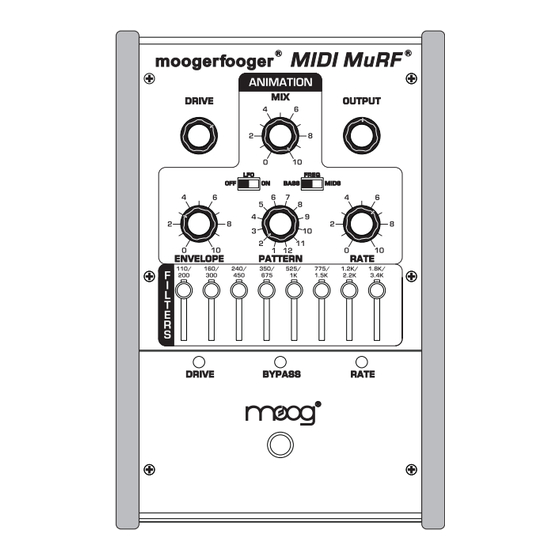
The MIDI MuRF’s FILTERS The MIDI MuRF contains 8 filters that can be configured for bass or mid-frequency voicing by the FREQ slide switch on the front panel. In the BASS voicing, the lowest filter acts as a lowpass filter with a cutoff frequency of 110 Hz. - Page 8 can hear the effect of just the filters. 3) Make sure the effect is on, and MIX is at 4) Connect just the "left/mono" output to your amplification. You may want to experiment with the panel controls and switches as we discuss each of the parameters.
- Page 9 LFO slider switch. When the slider is in the "OFF" position, the filters’ center frequencies can be shifted by an expression pedal (such as the Moog EP-2) or CV plugged into the LFO/SWEEP Jack. To hear how this works, return to the basic setup described in Figure 5.
-
Page 10: Envelope Generators
ENVELOPE GENERATORS Now that we have explained the MIDI MuRF’s filters, let’s proceed with some more definitions to explain the Animation function. The term "Envelope" is used to describe the changes that occur to a musical sound, from its start to its end. A musical sound can have a rapid onset, like the plucking of a string or the striking of a drum. -
Page 11: The Midi Murf's Animation
well. Vintage sequencers were typically designed so there were a certain number of "steps". The term "step" refers to the individual components of a pattern. For instance in a bar of music in 4/4 you have four quarter notes. If the rhythmic activity is no more complicated than quarter notes, this would correspond to four steps. - Page 12 individual filters. Illustrations of all the Patterns are in Appendix A, page Return to the basic setting shown in figure 2, which features pattern 2. As you play your instrument through the MIDI MuRF, pay attention to the sound of the effect and how it Figure 10 - MIDS Pattern 2 corresponds to figure 10.
-
Page 13: The Midi Murf's Tap/Step Input
THE MuRF’S TAP/STEP INPUT The MIDI MuRF’s Animation can be synced to the tempo of the music using a Moog FS-1 footswitch plugged into the TAP/STEP input. Tapping three times activates the tap tempo feature of the MIDI MuRF. The MF-105M calculates the time in between taps and translates this into the rate for the pattern. -
Page 14: Audio Level Controls And Mixing
THE AUDIO LEVEL CONTROLS AND MIXING The DRIVE control adjusts the signal level at the MIDI MuRF’s circuit input. With this control you can set the right input level for virtually any instrument or line-level signal source. Turn this control counterclockwise for strong input signals, and clockwise for weaker sound sources. -
Page 15: Expression Pedals And Voltage Control
of the left and right outputs when both the left and right output jacks are used. Note that the odd-numbered filters are sent to the left channel, and the even-numbered filters are sent to the right channel. This allows for spreading a sound’s frequencies between two speakers. -
Page 16: Using Midi With The Midi Murf
position increases that value, pulling back to heel position decreases the value. The expression pedal inputs can also be used as control signal inputs. This enables you to use your MF-105M with virtually any control signal source: modular analog synthesizers, MIDI-to-CV converters, etc. You will find information on interfacing your MF-105M with external control signal sources in the Technical Information section on page 23. - Page 17 setting, and 13-24 are accessed by the PATTERN switch in the MIDS voicing setting. Using MIDI Program Change Messages values 0-23 accesses the MuRF patterns 1-24. This has no impact on the position of the FREQ switch, so that using MIDI, you can use any of the 24 patterns with either voicing, overriding the front panel PATTERN and FREQ switch positions.
- Page 18 MIX: CC8. When the MF-105M receives a CC8 message on the MIDI channel that is assigned, the value of the CC8 message overrides the setting of the front panel MIX control and any steady voltage at the MIX control input. Moving the front panel MIX control or modifying a voltage at the MIX control input restores this parameter to its front panel state.
- Page 19 setting (i.e. the switch in the ON position, and the MIDI CC85 value received is 0). Moving the front panel LFO switch restores this parameter to its front panel state. FREQ BASS/MIDS: CC86; Values 0-63=BASS; 64-127=MIDS. When the MF-105M receives a CC86 message on the MIDI channel that is assigned, the value of the CC86 message overrides the setting of the front panel FREQ switch if it is in the range of values that is opposite the current setting (i.e.
- Page 20 clock and returns the MIDI MuRF’s filters to control by the EGRs triggered by the current Pattern. If the Pattern selected has no Animation (i.e. factory default pattern 1) then upon receiving one of these CC messages, the corresponding filter level is set by that CC value, while all other filter levels are set to ON (before the sliders).
- Page 21 1/8 note (CC Values 084-089), Clock messages: 12 Dotted 1/16 (CC Values 090-096), Clock messages: 9 1/16 note (CC Values 097-102), Clock messages: 6 Dotted 1/32 (CC Values 103-108), Clock messages: 4 1/32 note(CC Values 109-115), Clock messages: 3 Dotted 1/64 (CC Values 116-121), Clock messages: 2 1/64 note (CC Values 122-127), Clock messages: 1 A MIDI Clock Stop Message will stop the Pattern’s playback until a MIDI Clock start message is received, a MIDI Clock Continue message...
- Page 22 that is assigned, the MIDI MuRF pattern clock stops running, and that filter’s EGR is fired. If a Note On is held until the EGR goes through its complete attack/decay cycle, a new Note On message is required to retrigger the EGR. An EGR is retriggered from the last point in the EGR cycle if retriggered before the Decay segment reaches the end of its cycle.
- Page 23 The MIDI MuRF can respond to three types of System Exclusive data: individual patterns, a complete set of 24 patterns, and firmware. The details of the MIDI MuRF System Exclusive implementation is published on the Moog website: www.moogmusic.com. page 23...
-
Page 24: Some Typical Setups
SOME TYPICAL SETUPS UPWARD STAIRCASE WITH RHYTHMIC VARIATION Here is a variation on the basic setting of figure 2 that shows off the ability of the MuRF to create rhythmic variations within the patterns. This is really nice with sustained chords or slowly arpeggiated playing. -
Page 25: Technical Information
TECHNICAL INFORMATION NOTE: The following information is intended for use by people who understand analog electronic circuitry and have enough practical experience to interconnect sophisticated electronic equipment correctly. FIRMWARE UPDATE VIA MIDI: The MF-105M can be enabled to receive MIDI SysEx data containing the Operating Firmware for the MIDI MuRF by powering up in what is called "Bootloader Mode". - Page 26 PEDAL INPUTS: All pedal control input jacks are 1/4" tip- ring-sleeve (stereo) phone jacks. The sleeves are grounded and the ring terminals are supplied with +5 volts which is current-limited. Figure 14 - EP-2 compatible wiring, The tip terminals receive the variable voltages from the pedals.
- Page 27 voltages to the tips of the pedal control input jacks. The LFO/SWEEP jack can also receive 0 to +5 Volt programming voltages. AUDIO PATH: The bypassed signal goes to the LEFT/ MONO output jack. Thus, when the MIDI MuRF is bypassed, the signal at the LEFT/ MONO output jack is the same as what your instrument is producing, and there is no signal at the right output jack.
-
Page 28: Appendix A: The Murf's Patterns
APPENDIX A: THE MuRF’s PATTERNS BASS FILTER VOICING 1) No Animation 2) Downward Staircase 3) Upward Cascade 4) DoubleX 5) Perpetual Motion 6) Stereo Pyramid page 28... - Page 29 7) Double Dip 8) Inverted Rhythmicon 9) Prime Number Rhythmicon 10) Folded Rhythmicon 11) Breakbeat 12) Big Beat page 29...
- Page 30 MIDS FILTER VOICING 1) No Animation 2) Upward Staircase 3) Downward Cascade 4) Criss Cross 5) Brownian Motion 6) Random-like page 30...
- Page 31 7) Downward Band Expansion 8) Down and Up 9) Pulsar 10) Growing and Shrinking Band 11) Double Cascade 12) Rhythmicon page 31...
-
Page 32: Appendix B: Midi Implementation Chart
APPENDIX B: MIDI Implementation Chart MF-105M MIDI MuRF MIDI Implementation Chart Date: 08/24/09 version: 1.4 Transmitted Recognized Remarks Function Basic Default Channel Changed 1-16 Default ********** * MIDI CC102 Mode Messages ********** ********** recognized as Mode Altered ********** ********** 1 (all channels) Note *see page 21 of Number True voice... -
Page 33: Appendix C: Warranty Information
APPENDIX C: WARRANTY INFORMATION LIMITED WARRANTY Moog Music warrants that its products will be free from defects in materials or workmanship, and shall conform to specifications current at the time of shipment, for a period of one year from date of purchase. -
Page 34: Appendix D - Mf-105 Specifications
Appendix D: MF-105M SPECIFICATIONS DESCRIPTION: Analog effects module incorporating two functions: 8 – band Resonant Filter Bank and 24-Pattern Sequencer triggering Volume Envelopes for 8 Filters with CV and MIDI control. FRONT PANEL FEATURES: DRIVE rotary control - adjusts the gain of the audio input to the effect. OUTPUT rotary control - balances the level of MuRF’s signal when the effect is on with the bypassed signal when the effect is off. -
Page 35: General Specifications
POWER REQUIREMENTS: 120 volt, 5W. 220 volt power adaptor available on special order Moog®, Moogerfooger®, and MuRF® are registered trademarks of Moog Music Inc. ©2009 Moog Music Inc. MOOG MUSIC Inc. 2004E RIVERSIDE DRIVE ASHEVILLE, NC 28804 Phone: (828) 251-0090 Email: info@moogmusic.com...
Need help?
Do you have a question about the MIDI MuRF MF-105M and is the answer not in the manual?
Questions and answers