Motorola ASTRO XTS 5000 User Manual
Digital portable radio model ii
Hide thumbs
Also See for ASTRO XTS 5000:
- Detailed service manual (374 pages) ,
- User manual (164 pages) ,
- Basic service manual (128 pages)
Table of Contents
Advertisement
Quick Links
Advertisement
Table of Contents

Related Manuals for Motorola ASTRO XTS 5000


Summary of Contents for Motorola ASTRO XTS 5000
- Page 1 ® ASTRO ™ XTS 5000 Digital Portable Radio Model I I User Guide...
-
Page 2: Computer Software Copyrights
Also, be sure to retain this publication for future reference. Computer Software Copyrights The Motorola products described in this manual may include copyrighted Motorola computer programs stored in semiconductor memories or other media. Laws in the United States and other... - Page 3 ™ Radio On/Off ASTRO Digital XTS 5000 ® When acknowledgment is received, you hear four beeps; alarm ends; radio exits emer- On - On/Off/Volume knob clockwise. Model II Radio gency. Off - On/Off/Volume knob counterclockwise. Quick Reference Card Send Emergency Call Zones/Channels Radio on and press Emergency button.
-
Page 4: Menu Navigation
Display Status Symbols Menu Entries (Use With Menu Navigation) Entry Menu Selection Page Receiving an individual call Entry Menu Selection Page TX Power Level Smart Battery BATT The radio is in the view or program mode; Reprogram Request RPGM On Steady = view mode; Flashing = Private Call CALL program mode... -
Page 5: Table Of Contents
Menu Select Buttons ..............7 Menu Entry Features ..............8 Home Button ................8 , Motorola, ASTRO, ASTRO 25, XTS 5000, Private Conversation, and SmartZone are trademarks of Motorola, Inc. P25 radios contain technology patented by Digital Voice Systems, Inc. - Page 6 Contents Alpha Button ................8 4-Way Navigation Button ............8 LED Indicators ...................9 Alert Tones ..................10 Standard Accessories ..............13 Battery ..................13 Smart Battery Condition ............15 Antenna ..................16 Belt Clip ..................17 Universal Connector Cover ............18 Radio On and Off ................19 Turn the Radio On ..............19 Turn the Radio Off ..............19 Zones and Channels ...............20 Select a Zone ................20...
- Page 7 Contents Lists ....................37 View a List ................37 Scan List Empty ................ 37 Edit a Scan List ................. 38 Scan ....................43 Types of Scan Lists ..............43 Types of Scanning ..............43 Turn Scan On or Off ..............44 Delete a Nuisance Channel ............
- Page 8 Contents PTT ID .....................66 Receive ..................66 Transmit ..................66 View Your Radio’s ID Number ............67 Dynamic Regrouping (ASTRO 25 Trunking Only) ......68 Reprogram Request ..............68 Select Enable / Disable .............70 Trunking System Controls ...............71 Failsoft ..................71 Out-of-Range ................71 Site Lock ...................72 Site Trunking ................73 Site View and Change ..............74 Time and Date .................75...
- Page 9 Contents Ear Microphones (Require Radio Interface Module) ....90 Radio Interface Modules for Ear Microphones ......90 Remote Speaker and Public Safety Microphones ....90 Vehicular Adapters ................90 Accessories ................90 Allied Models ................91 Glossary ........93 Commercial Warranty .
- Page 10 Contents Notes...
-
Page 11: User Safety, Training, And General Information
Compliance with RF Energy Exposure Standards Your Motorola two-way radio is designed and tested to comply with a number of national and international standards and guidelines (listed below) regarding human exposure to radio frequency electromagnetic energy. This radio complies with the IEEE (FCC) and ICNIRP... -
Page 12: Operational Instructions And Training Guidelines
(2.5 to 5 cm) away from the lips. Body-worn operation • Always place the radio in a Motorola approved clip, holder, holster, case, or body harness for this product. Use of non- Motorola-approved accessories may exceed FCC RF exposure guidelines. -
Page 13: Electromagnetic Interference/Compatibility
Motorola approved replacement batteries. Use of non- Motorola-approved antennas or batteries may exceed FCC RF exposure guidelines. Approved Accessories • For a list of Motorola approved accessories see the appendix of this user manual or visit the following website which lists approved accessories: http://www.motorola.com/cgiss/portables/xts5000.shtml... -
Page 14: Medical Devices
User Safety, Training, and General Information Medical Devices Pacemakers The Advanced Medical Technology Association (AdvaMed) recommends that a minimum separation of 6 inches (15 centimeters) be maintained between a handheld wireless radio and a pacemaker. These recommendations are consistent with those of the U.S. Food and Drug Administration. -
Page 15: Operational Warnings
User Safety, Training, and General Information Operational Warnings For Vehicles With an Air Bag Do not place a portable radio in the area over an air bag or in the air bag deployment area. Air bags W A R N I N G inflate with great force. -
Page 16: Operational Cautions
User Safety, Training, and General Information Operational Cautions Antennas Do not use any portable radio that has a damaged antenna. If a damaged antenna comes into contact C a u t i o n with your skin, a minor burn can result. Batteries All batteries can cause property damage and/or bodily injury such as burns if a conductive material such as... - Page 17 User Safety, Training, and General Information FMRC Approval labels are attached to the radio to identify the unit as being FM Approved for specified hazardous atmospheres. This label specifies the APPROVED hazardous Class/Division/Group along with the part number of the battery that must be used. Depending on the design of the portable unit, this FM label can be found on the back or the bottom of the radio housing.
- Page 18 Product unit in any way that exposes the internal electrical circuits of the unit. Radios must ship from the Motorola manufacturing facility with the hazardous atmosphere capability and FM Approval labeling. Radios will not be “upgraded” to this capability and labeled in the field.
-
Page 19: Repair Of Fmrc Approved Products
Repair of FMRC Approved Products REPAIRS FOR MOTOROLA PRODUCTS WITH FMRC APPROVAL ARE THE RESPONSIBILITY OF THE USER. You should not repair or relabel any Motorola-manufactured communication equipment bearing the FMRC Approval label (“FMRC Approved Product”) unless you are familiar with the current FMRC Approval standard for repairs and service (“Class Number 3605”). - Page 20 This FM Approved portable and battery combination must be strictly observed. There must be no substitution of items, even if the substitute has been previously Approved with a different Motorola communications equipment unit. Approved configurations are listed in the FM Approval Guide published by FMRC, or in the product FM Supplement.
- Page 21 User Safety, Training, and General Information Guide, or the Approval Standard Class Number 3605 document for repairs and service, can be ordered directly from Factory Mutual Research Corporation located in Norwood, Massachusetts. xvii ASTRO Digital XTS 5000 Model II...
- Page 22 User Safety, Training, and General Information Notes xviii...
-
Page 23: General Radio Operation
General Radio Operation Notations Used in This Manual Throughout the text in this publication, you will notice the use of WARNINGS, Cautions, and Notes. These notations are used to emphasize that safety hazards exist, and the care that must be taken or observed. -
Page 24: Your Xts 5000 Model Ii Radio
General Radio Operation Your XTS 5000 Model II Radio MAEPF-27192-A... -
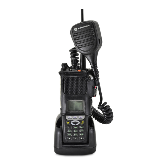
Page 25: Physical Features Of The Xts 5000 Model Ii Radio
General Radio Operation Physical Features of the XTS 5000 Model II Radio Table 1: Physical Features No. Feature Page No. Feature Page Antenna Home Button On/Off/Volume Control Battery Knob 10 Alpha Button Microphone 11 Display PTT (Push-to-Talk) 12 Speaker Button Menu Select Buttons 13 Universal Connector 4-Way Navigation... -
Page 26: Display
General Radio Operation Table 2: Programmable Features Feature Page Feature Page Feature Page Call Alert Phone Site Lock/Unlock Call Response PL Defeat Site Search Channel Private Call Smart Battery Dynamic Priority Repeater/Direct Status Emergency Reprogram TX Power Level Request Keypad Mute Scan List Volume Set Programming... -
Page 27: Backlight
General Radio Operation Backlight If poor light conditions make the display, keypad, or channel numbers (around the 16-Position Select knob) difficult to read, turn on the radio’s backlights by pressing the preprogrammed Light button. These lights will remain on for a preprogrammed time before they turn off automatically, or you can turn them off immediately by pressing the Light button again. - Page 28 General Radio Operation Table 3: Status Symbols (Continued) Symbol Indication Page No. Talkaround • On = you are talking directly to another radio, not through a repeater, 62-63 during conventional operation only • Off = you are talking through a repeater Monitor (Carrier Squelch) 25, 30,...
-
Page 29: Text
General Radio Operation Text Depending on the information being shown, the display can have several rows of text. Menu Entry (Softkey) The bottom row of the display contains one to three menu entries (also known as softkeys). The menu entries allow you to select one of several menus to access the radio’s features. -
Page 30: Menu Entry Features
General Radio Operation Menu Entry Features Table 4: Menu Entries Menu Menu Feature Page Feature Page Selection Selection Smart Battery TX Power Level BATT Private Call Reprogram CALL RPGM Request Channel Selection Scan On/Off CHAN SCAN Time and Date Site Lock/ CLCK SITE Unlock... -
Page 31: Led Indicators
General Radio Operation LED Indicators The LED on top of the radio indicates the radio’s operating status: Table 5: LED Indicators LED Indicator What it Means Radio transmitting Flashing red • Channel busy, or • Low battery (while transmitting) Double flashing red Receiving encrypted audio Flashing green Receiving an individual call... -
Page 32: Alert Tones
General Radio Operation Alert Tones An alert tone is a sound or group of sounds. Your radio uses alert tones to inform you of your radio’s conditions. The following table lists these tones and when they occur. Table 6: Alert Tones You Hear Tone Name Heard... - Page 33 General Radio Operation Table 6: Alert Tones (Continued) You Hear Tone Name Heard Valid Key-Press when correct key is pressed Radio Self-Test when radio passes its power-up Pass self test Clear Voice at beginning of a non-coded communication Short, Medium- Priority when activity on a priority channel Pitched...
- Page 34 General Radio Operation Table 6: Alert Tones (Continued) You Hear Tone Name Heard Fast Ringing when system is searching for target of Private Conversation call Enhanced Call when waiting for target of Private Ringing Sent Conversation call to answer the call Phone Call when a land-to-mobile phone call is Received...
-
Page 35: Standard Accessories
Prior to using a new battery, charge it for a minimum of 16 hours to ensure optimum capacity and performance. For a list of Motorola-authorized batteries available for use with your XTS 5000 radio, see “Batteries” on page 87. Note: When charging a battery attached to a radio, turn the radio off to ensure a full charge. - Page 36 General Radio Operation Attach the Battery With the radio turned off, insert the top edge of the battery into the radio’s frame as shown. Rotate the battery toward the radio and press down until the battery clicks into place. Remove the Battery With the radio turned off, press the release button on the bottom of the battery until...
-
Page 37: Smart Battery Condition
General Radio Operation Smart Battery Condition This feature lets you view the condition of your Smart Battery. Use the Menu Press u to find BATT. BATT Press D, E, or F CAPACITY directly below BATT. INIT 10/01 EST CHGS Note: If a Smart Battery is not SMART BATT powering your radio. -
Page 38: Antenna
General Radio Operation Antenna For information regarding available antennas, see page 85. Attach the Antenna With the radio turned off, turn the antenna clockwise to attach it to the radio. Remove the Antenna With the radio turned off, turn the antenna counter-clockwise to remove it from the radio. -
Page 39: Belt Clip
General Radio Operation Belt Clip Attach the Belt Clip Align the grooves of the belt Grooves clip with those of the battery. Slots Battery Battery Press the belt clip downward until you clear a click. Slots Battery Battery Remove the Belt Clip Use a flat-bladed object to press the belt clip tab away Metal... -
Page 40: Universal Connector Cover
General Radio Operation Universal Connector Cover The universal connector is located on the antenna side of the radio. It is used to connect accessories to the radio. Note: To prevent damage to the connector, shield it with the connector cover when not in use. Remove the Connector Cover Insert a flat-bladed screwdriver into the area... -
Page 41: Radio On And Off
General Radio Operation Radio On and Off Turn the Radio On Turn the On/Off/Volume Control knob clockwise. Note: If the power-up test is SELF TEST successful, you briefly see SELF TEST, then the home display. Note: If the power-up test is ERROR XX/YY unsuccessful, you see ERROR XX/YY. -
Page 42: Zones And Channels
General Radio Operation Zones and Channels A zone is a grouping of channels. A channel is a group of radio characteristics, such as transmit/receive frequency pairs. Before you use your radio to receive or send messages, you should select the zone and channel. Select a Zone Use the Menu Press u to find ZONE. -
Page 43: Select A Channel
General Radio Operation Note: If the zone you selected FIRE UNPROGRAMMED DISP NW is unprogrammed, repeat step 1. Press h to confirm the FIRE DISP NW displayed zone and channel. Select a Channel Consult a qualified radio technician for the right choice between the following methods: Method 1: Use the Preprogrammed 16-Position Select Knob After the zone you want is... - Page 44 General Radio Operation Press h to confirm the DISP SE displayed zone and channel. Press the PTT button to transmit on the displayed zone/channel.
-
Page 45: Receive / Transmit
General Radio Operation Receive / Transmit Radio users who switch from analog to digital radios often assume that the lack of static on a digital channel is an indication that the radio is not working properly. This is not the case. Digital technology quiets the transmission by removing the “noise”... -
Page 46: Use The Preprogrammed Monitor Button
General Radio Operation Adjust the Volume Control knob if necessary. Adjust Level Release the Volume Set button. Press and hold the PTT button to transmit. The LED lights RED while transmitting. Release the PTT button to receive (listen). Use the Preprogrammed Monitor Button Turn the radio on and select the desired zone and channel. -
Page 47: Conventional Mode Operation
General Radio Operation Conventional Mode Operation Your radio may be programmed to receive Private-Line® (PL) calls: Momentarily press the Monitor button to listen for activity. The Carrier Squelch indicator is displayed. Press and hold the Monitor button to set continuous monitor operation. - Page 48 General Radio Operation Notes...
-
Page 49: Common Radio Features
Common Radio Features Selectable Power Level This feature lets you select the power level at which your radio will transmit. The radio will always turn on to the default setting. This feature must be preprogrammed by a qualified radio technician. •... -
Page 50: Use The Preprogrammed Transmit Power Level Switch
Common Radio Features Use the Preprogrammed Transmit Power Level Switch Move the TX Power Level switch to the Low Power position. The power level is set to Low. Move the TX Power Level switch to the HIgh Power position. The power level is set to High. -
Page 51: Mute Or Unmute Keypad Tones
Common Radio Features Mute or Unmute Keypad Tones You can turn the keypad tones on or off. Use the Menu Press u to find MUTE. MUTE Press D, E, or F TONES OFF directly below MUTE. The current state is shown. TONES ON Press D, E, or F directly below OFF or ON. -
Page 52: Conventional Squelch Operation
Common Radio Features Conventional Squelch Operation Analog Options Tone Private Line (PL), Digital Private-Line (DPL), and carrier squelch can be available (preprogrammed) per channel. When in This condition occurs Carrier squelch (C) You hear all traffic on a channel. PL, or DPL The radio responds only to your messages. -
Page 53: Pl Defeat
Common Radio Features PL Defeat With this feature, you can override any coded squelch (DPL or PL) that might be preprogrammed to a channel. Place the preprogrammed PL Defeat switch in the PL Defeat position. You can now hear any activity on the chan- nel. -
Page 54: Time-Out Timer
Common Radio Features Time-out Timer The time-out timer turns off your radio’s transmitter. The timer is set for 60 seconds at shipment, but it can be programmed from 0 to 7.75 minutes (465 seconds) by a qualified radio technician. Hold down the PTT button •... -
Page 55: Emergency
Common Radio Features Emergency If the top (orange) button is programmed to send an emergency signal, then this signal overrides any other communication over the selected channel. Your radio can be programmed for the following: • Emergency Alarm • Emergency Call •... -
Page 56: Send An Emergency Call
Common Radio Features When you receive the ACK RECEIVED dispatcher’s acknowledgment, you see • Four tones ACK RECEIVED, four tones • Alarm ends sound, the alarm ends, and • Radio exits emergency the radio exits the emergency mode. If no acknowledgement is NO ACKNOWLDG received, you see NO ACKNOWLDG, the alarm ends,... -
Page 57: Send A Silent Emergency Alarm
Common Radio Features Note: To exit emergency at any time, press and hold the Emergency button. Press and hold the PTT button and announce your emergency into the microphone. Release the PTT button to end the transmission and wait for a response from the dispatcher. -
Page 58: Emergency Keep-Alive
Common Radio Features Note: For ALL Emergency signals, when changing channels: • If the new channel is also programmed for Emergency, you can change channels while in Emergency operation. The emergency alarm or call continues on the new channel. • If the new channel is NOT programmed for Emergency, you hear an invalid tone until you exit the Emergency state or change to a channel programmed for emergency. -
Page 59: Lists
Common Radio Features Lists You can use lists to store frequently used numbers and associate them with names. There are four list types: • Call • Page • Phone • Scan View a List Press u to find VIEW: VIEW Press D, E, or F directly below VIEW. -
Page 60: Edit A Scan List
Common Radio Features Edit a Scan List This feature lets you change scan list members and priorities. Use the Menu Press u to find PROG. PROG Press D, E, or F SCAN directly below PROG. You see SCAN. Press D, E, or F FIRE DISP NW p directly below SCAN. - Page 61 Common Radio Features Press v or u to select more channels to be added or deleted. Use the 16-Position Select knob to select additional channels to be added or deleted. Press h to exit scan list programming and return to the home display.
- Page 62 Common Radio Features = this channel is in the scan list. = this channel is in the scan list as the priority 2 channel. (dot flashing) = this channel is in the scan list as the priority 1 channel. = the channel is removed from the scan list. Press v or u to select more scan list members whose scan status you want to...
- Page 63 Common Radio Features SEL = add the currently displayed channel to the scan list. DEL = delete the currently displayed channel from the scan list. RCL = view the next member of the scan list. When adding a priority chan- nel, press D, E, or F below SEL additional times to = this channel is in the scan list.
- Page 64 Common Radio Features Change the Scan List Status Only Move the Scan List FIRE DISP NW p Programming switch to the Programming position. You see the first list member. p (flashing) indicates the programming mode. Press v or u to find the member you want to change.
-
Page 65: Scan
Common Radio Features Scan The scan feature allows you to monitor traffic on different channels by scanning a preprogrammed list of channels. Your radio can have up to 32 different scan lists. These lists must be preprogrammed by a qualified radio technician. •... -
Page 66: Turn Scan On Or Off
Common Radio Features Automatic Scanning When selected, a channel with autoscan (Autoscan) automatically begins scanning its associated scan list. The radio continues auto scanning until you select a channel without autoscan enabled. Operator-Selectable Scan can be programmed by a qualified Scan radio technician to be selected by either a menu or a preprogrammed Scan switch. -
Page 67: Delete A Nuisance Channel
Common Radio Features Delete a Nuisance Channel When the radio scans to a channel that you do not wish to hear (nuisance channel), you can temporarily delete the channel from the scan list. When the radio is locked onto the channel to be deleted, press the preprogrammed Nuisance Delete button. -
Page 68: Conventional Scan Only
Common Radio Features Conventional Scan Only Make a Dynamic Priority Change While the radio is scanning, the dynamic priority change feature lets you temporarily change any channel in a scan list (except the priority- one channel) to the priority-two channel. The replaced priority-two channel becomes a non-priority channel. -
Page 69: Telephone Calls (Astro 25 Trunking Only)
Common Radio Features Telephone Calls (ASTRO 25 Trunking Only) Use your radio to make calls similar to standard phone calls. A landline phone can be used to call a radio, or a radio can be used to call a landline phone. Quick Access (One-Touch) If your radio is preprogrammed for Quick Access (One-Touch) Phone Call, you can make a call to one preprogrammed phone number... -
Page 70: Answer A Phone Call
Common Radio Features Answer a Phone Call Use the preprogrammed Call Response button to answer a call. When a phone call is • Telephone-type ringing received, you hear a • Flashing GREEN LED telephone-type ringing, the PHONE CALL LED flashes GREEN, the call received symbol ( ) flashes, and PHONE CALL is displayed. -
Page 71: Select A Phone Number
Common Radio Features Select a Phone Number Press u to find the phone POLICE number you want. 555-8523 LNUM Note: Press LNUM to go to the last number dialed. Go to “Make a Phone Call”, below. Make a Phone Call Press and release the PTT button to dial the phone number. - Page 72 Common Radio Features Table 7: Phone Call Display and Alert Prompts When you press the PTT button NO PHONE and the phone system is not available, you hear a long tone. • A long tone Press h to hang up. The radio returns to the home display.
-
Page 73: Enhanced Private Conversation Calls (Astro 25 Trunking Only)
Common Radio Features Enhanced Private Conversation Calls (ASTRO 25 Trunking Only) These one-to-one calls between two radios are not heard by others in the current talkgroup. The calling radio automatically verifies that the receiving radio is active on the system and can display the caller’s ID. Quick Access (One-Touch) If your radio is preprogrammed for Quick Access (One-Touch) Private Call, you can make a call to one preprogrammed ID number without... -
Page 74: Answer A Private Call
Common Radio Features Answer a Private Call Use the preprogrammed Call Response button to answer a call. When a Private Call is • Two tones received, you hear two alert • Flashing GREEN LED tones, the LED flashes CALL RECEIVD GREEN, the call received symbol ( ) flashes, and CALL... -
Page 75: Initiate A Private Call
Common Radio Features Initiate a Private Call Press u to find CALL. CALL Press D, E, or F ID: 00722588 directly below CALL. You see LIST the last transmitted or received ID number. Go to “Select an ID Number”, below. Go to “Make a Private Call”... -
Page 76: Make A Private Call
Common Radio Features Make a Private Call Press the PTT button to start the Private Call. The called ID is momentarily FIRE CHIEF displayed, then you see ID: 00825682 PLEASE WAIT. ID: 00722588 PLEASE WAIT When you are connected, FIRE CHIEF you see the called ID. -
Page 77: Call Alert Paging (Astro 25 Trunking Only)
Common Radio Features Call Alert Paging (ASTRO 25 Trunking Only) Call Alert allows your radio to work like a pager. Even if other users are away from their radios, or if they are unable to hear their radios, you can still send them a Call Alert page. You can also verify if a radio is active on the system. -
Page 78: Answer A Call Alert Page
Common Radio Features Answer a Call Alert Page When a Call Alert Page is • Four repeating alert tones received, you hear four • Flashing GREEN LED repeating alert tones, the PAGE RECEIVD LED flashes GREEN, the call received symbol ( ) flashes, and PAGE RECEIVD is displayed. -
Page 79: Send A Call Alert Page
Common Radio Features Send a Call Alert Page Press the PTT button to send PLEASE WAIT the Call Alert to the displayed number. You see PLEASE WAIT. When you are connected, you see the home display. Press and hold the PTT button to talk;... -
Page 80: Conventional Talkgroup Calls (Conventional Operation Only)
Common Radio Features Conventional Talkgroup Calls (Conventional Operation Only) Talkgroup Call lets you define a group of conventional system users so that they can share the use of a conventional channel. Encryption keys are slaved to talkgroups. When talkgroups are enabled, encryption keys are changed by changing the active talkgroup. - Page 81 Common Radio Features Press h or the PTT button, or turn the 16-Position Select knob to exit. ASTRO Digital XTS 5000 Model II...
-
Page 82: Status Calls (Astro 25 Trunking Only)
Common Radio Features Status Calls (ASTRO 25 Trunking Only) You can send data calls to the dispatcher about a predefined status. Each status can have a up to a 12-character name. A maximum of eight status conditions is possible. Send a Status Call Use the Menu Press u to find STS. - Page 83 Common Radio Features Note: No traffic is heard on trunked channels while Status Calls is selected. If the radio detects no Status Call activity for six seconds, an alert tone sounds until the PTT button is pressed. Use the Preprogrammed Status Button Press the Status button.
-
Page 84: Repeater Or Direct Operation
Common Radio Features Repeater or Direct Operation Also known as “talkaround operation,” DIRECT lets you bypass the repeater and connect directly to another radio. The transmit and receive frequencies are the same. REPEATER operation increases radio’s range by connecting with other radios through a repeater. - Page 85 Common Radio Features Use the Preprogrammed Repeater/Direct Switch Place the Repeater/Direct switch in either the Repeater or the Direct position. If DIR is selected, the display shows ASTRO Digital XTS 5000 Model II...
-
Page 86: Smart Ptt (Conventional Only)
Common Radio Features Smart PTT (Conventional Only) Smart PTT is a per-channel, programmable feature used in conventional radio systems to keep radio users from talking over other radio conversations. When smart PTT is enabled in your radio, you will not be able to transmit on an active channel. -
Page 87: Special Radio Features
Secure radio operation provides the highest commercially available level of voice security on both trunked and conventional channels. Unlike other forms of security, Motorola digital encryption provides signaling that makes it virtually impossible for others to decode any part of an encrypted message. -
Page 88: Ptt Id
Special Radio Features PTT ID Receive This feature allows you to see the radio ID number of the radio you are currently receiving. This ID can be a maximum of eight characters and can be viewed by both the receiving radio and the dispatcher. Transmit Your radio’s ID number is automatically sent every time the PTT button is pressed. -
Page 89: View Your Radio's Id Number
Special Radio Features View Your Radio’s ID Number Use the Menu Press u to find CALL or PAGE. CALL or PAGE Press D, E, or F directly below CALL or PAGE. Press v . MY ID: 12345678 Use the Preprogrammed Call or Page Button Press the Call or Page button. -
Page 90: Dynamic Regrouping (Astro 25 Trunking Only)
Special Radio Features Dynamic Regrouping (ASTRO 25 Trunking Only) The dynamic regrouping feature lets the dispatcher temporarily reassign selected radios to a single special channel so they can communicate with each other. This feature is typically used during special operations and is enabled by a qualified radio technician. You will not notice whether your radio has this feature enabled until a dynamic regrouping command is sent by the dispatcher. - Page 91 Special Radio Features If you hear one beep • One beep - Press the PTT button to send the reprogram request again. - Press h to cancel and return to the home display. If you hear five beeps, the • Five beeps reprogram request was acknowledged by the dis-...
-
Page 92: Select Enable / Disable
Special Radio Features If you hear one beep - Press the PTT button to send the reprogram request again - Press h to hang up and return to the home display. If you hear five beeps, the reprogram request was acknowledged by the dis- patcher. -
Page 93: Trunking System Controls
Special Radio Features Trunking System Controls Failsoft The Failsoft system ensures continuous radio communications during a trunked system failure. If a trunking system fails completely, the radio goes into failsoft operation and automatically switches to its failsoft channel. During failsoft operation: Your radio transmits and receives FAILSOFT in conventional operation on a... -
Page 94: Site Lock
Special Radio Features Site Lock This feature allows your radio to lock onto a specific site and not roam among wide-area talkgroup sites. This feature should be used with caution, since it inhibits roaming to another site in a wide-area system. -
Page 95: Site Trunking
Special Radio Features Press and hold the Site Lock/ Unlock button to find the desired lock state, SITE UNLOCKD or SITE LOCKED. Site Trunking If the zone controller loses communication with any site, that site reverts to site trunking. You see the currently selected SITE TRUNKNG zone/channel combination and SITE TRUNKNG. -
Page 96: Site View And Change
Special Radio Features Site View and Change You can view the number of the current site or force your radio to change to a new one. View the Current Site Press the preprogrammed Site Search button. SITE 2 The display momentarily shows the name of the current site and its corresponding received signal strength indica-... -
Page 97: Time And Date
Special Radio Features Time and Date Using this special feature, you can program the time and date as you might with other electronic devices. The clock display is enabled by a qualified radio technician. The default time setting is a 12-hour 12HR 00:00AM clock. - Page 98 Special Radio Features Press x or y to change the 24HR 03:54 selected item. MDY 03/07/01 SAVE Note: Press h at any time to return to the home display without saving your changes. Press u one or more times to 12HR 03:54AM move to an item you wish to MDY 03/07/01...
- Page 99 Special Radio Features When you have made all your changes, press D, E, or F directly below SAVE to save your changes and return to the home display. Note: When you have made all your changes, press D, E, or F directly below SAVE to save your changes and return to the home display.
- Page 100 Special Radio Features Notes...
-
Page 101: Helpful Tips
Helpful Tips Radio Care Things to Avoid • The XTS 5000 radio casting has two vent ports that allow for pressure equalization in the radio. Never poke these vents with any objects, such as needles, tweezers, or screwdrivers. This C a u t i o n could create leak paths into the radio and the radio’s submergibility will be lost. -
Page 102: Cleaning
Helpful Tips Cleaning To clean the external surfaces of your radio: Combine one teaspoon of mild dishwashing detergent to one gallon of water (0.5% solution). Apply the solution sparingly with a stiff, non-metallic, short- bristled brush, making sure excess detergent does not get entrapped near the connectors, controls or crevices. -
Page 103: Service
Helpful Tips Service Proper repair and maintenance procedures will assure efficient operation and long life for this product. A Motorola maintenance agreement will provide expert service to keep this and all other communication equipment in perfect operating condition. A nationwide service organization is provided by Motorola to support maintenance services. -
Page 104: Battery
25% discharge, will last even longer. Charging the Battery Motorola batteries are designed specifically to be used with a Motorola charger and vice-versa. Charging in non-Motorola equipment may lead to battery damage and void the battery warranty. -
Page 105: Battery Recycling And Disposal
Contact your local waste management agency for specific requirements and information in your area. Motorola fully endorses and encourages the recycling of NiCd batteries. In the U.S. and Canada, Motorola participates in the ASTRO Digital XTS 5000 Model II... - Page 106 Helpful Tips nationwide Rechargeable Battery Recycling Corporation (RBRC) program for NiCd battery collection and recycling. Many retailers and dealers participate in this program. For the location of the drop-off facility closest to you, access RBRC’s Internet web site at www.rbrc.com or call 1-800-8-BATTERY. This internet site and telephone number also provide other useful information concerning recycling options for consumers, businesses, and governmental agencies.
-
Page 107: Antenna
Helpful Tips Antenna Radio Operating Frequencies Before installing the antenna, 800 MHz make sure it matches your Whip 800 MHz radio’s operating frequency. Stubby Antennas are frequency sensitive and are color coded Helical according to their frequency range. The color code indicator is located in the center of the antenna’s base. - Page 108 Helpful Tips Notes...
-
Page 109: Accessories
Accessories Motorola provides the following approved accessories to improve the productivity of your XTS 5000 portable two-way radio. Antennas NAF5037 800 MHz Whip, Halfwave (806-870 MHz) NAF5042 800 MHz Stubby, Quarterwave (806-870 MHz) NAF5080 700/800 MHz Whip (764-870 MHz) Batteries... -
Page 110: Carry Accessories
Accessories Carry Accessories Belt Clips NTN8266 Belt Clip Kit (Compatible with Clamshell Batteries) Belt Loops NTN8040 Belt Loop, Swivel, Leather, 3.0”, High-Activity (For use only with the high-activity leather swivel snap carry cases.) Carry Cases NTN8381 Leather High Activity, 3.0”, Swivel Belt Loop, Model II and III Radios Chargers NTN1873... -
Page 111: Enhanced And Multi-Unit Line Cords
Accessories NTN1669 Single-Unit, Tri-Chemistry, Rapid Rate, 230 V (3- prong UK Plug) NTN4796 Multi-Unit, Tri-Chemistry, Rapid Rate,110 V NTN9176 Vehicular, Tri-Chemistry and compatible with PAC•RT WPLN4111 Impres™ Single-Unit, Tri-Chemistry,110 V Enhanced and Multi-Unit Line Cords NTN7373 110 V Interchangeable Line NTN7374 220 V Interchangeable Line (2 prong Euro plug) NTN7375... -
Page 112: Ear Microphones (Require Radio Interface Module)
Accessories NMN6259 Medium Weight, Behind-the-Head with In-Line PTT Switch RMN4049 Temple Transducer Ear Microphones (Require Radio Interface Module) BDN6677 Ear Mic, Standard — 95 dB (Black) BDN6678 Ear Mic, Standard — 95 dB (Beige) Radio Interface Modules for Ear Microphones BDN6671 Voice-activated Interface Module BDN6708... -
Page 113: Allied Models
Accessories NTN8560 Vehicular Adapter, Mini-U, Open Faced NTN8561 Vehicular Adapter, Mini-U, Closed Faced NTN9176 Vehicular Charger, XTS PLN7737 Handheld Control Head Allied Models N1799 Vehicular Adapter, Mini-U, Closed Faced N2001 Vehicular Adapter, Mini-U, Open Face N2002 Vehicular Adapter, BNC, Open Face N2003 Vehicular Adapter, BNC, Closed Face ASTRO Digital XTS 5000 Model II... - Page 114 Accessories Notes...
-
Page 115: Glossary
Glossary This is a list of specialized terms used in this manual. Acknowledgment of communication. Active Channel A channel that has traffic on it. Analog Signal An RF signal that has a continuous nature rather than a pulsed or discrete nature. Call Alert Privately page an individual by sending an audible tone. - Page 116 Glossary Deadlock Displayed by the radio after three failed attempts to unlock the radio.The radio must be powered off and on prior to another attempt. Digital Private Line A type of coded squelch using data bursts. (DPL) Similar to PL except a digital code is used instead of a tone.
- Page 117 Glossary Network Access Network Access Code (NAC) operates on Code digital channels to reduce voice channel interference between adjacent systems and sites. NiCd Nickel-cadmium. NiMH Nickel-metal-hydride. Non-tactical/Revert The user will talk on a preprogrammed emergency channel. The emergency alarm is sent out on this same channel. Page A one-way alert, with audio and/or display messages.
- Page 118 Glossary Selective Switch Any digital P25 traffic having the correct Network Access Code and the correct talkgroup. Squelch Special electronic circuitry, added to the receiver of a radio, that reduces, or cuts off, unwanted signals before they are heard in the speaker.
-
Page 119: Commercial Warranty
Product Accessories One (1) Year Motorola, at its option, will at no charge either repair the Product (with new or reconditioned parts), replace it (with a new or reconditioned Product), or refund the purchase price of the Product during the warranty period provided it is returned in accordance with the terms of this warranty. - Page 120 Product item serial number) in order to receive warranty service and, also, deliver or send the Product item, transportation and insurance prepaid, to an authorized warranty service location. Warranty service will be provided by Motorola through one of its authorized warranty service locations. If you first contact the company...
- Page 121 Commercial Warranty which sold you the Product, it can facilitate your obtaining warranty service. You can also call Motorola at 1-888-567-7347 US/Canada. V. WHAT THIS WARRANTY DOES NOT COVER: A) Defects or damage resulting from use of the Product in other than its normal and customary manner.
- Page 122 A) that MOTOROLA will be notified promptly in writing by such purchaser of any notice of such claim; B) that MOTOROLA will have sole control of the defense of such suit and all negotiations for its settlement or compromise; and C) should the Product or parts become, or in MOTOROLA’s...
- Page 123 Commercial Warranty the use of ancillary equipment or software not furnished by MOTOROLA which is attached to or used in connection with the Product. The foregoing states the entire liability of MOTOROLA with respect to infringement of patents by the Product or any parts thereof.
- Page 124 Commercial Warranty Notes...
-
Page 125: Index
Index Numerics carry accessories belt clips ........88 4-way navigation button ....8 belt loops ......... 88 carry cases ......88 chargers accessories .........87 enhanced and multi-unit line alert tones ........10 cords ........89 alpha button ........8 charging the battery ....13 antenna common radio features .... - Page 126 Index failsoft ..........71 notations used in this manual ..1 general radio operation ....1 operational warnings ....xi glossary ........93 out-of-range ........ 71 headset / surveillance accessories phone call display and alert ear microphones ......90 prompts ....... 49, 50 earpieces ........89 physical features of the XTS 5000 headset accessories ....89 model II radio ......
- Page 127 Index the universal connector cover .18 trunking ........73 repeater or direct operation ..62 view and change reprogram request change the current site ..74 use the menu ......68 view the current site .... 74 use the preprogrammed smart reprogram request button ..69 battery condition request a new dynamic regrouping, use the menu ......
- Page 128 Index allied models ......91 view your radio’s ID number use the menu ......67 use the preprogrammed call or page button ......67 warranty ........97 your XTS 5000 model II radio ..2 zones and channels ....20...
- Page 130 Motorola, Inc. 8000 West Sunrise Boulevard Ft. Lauderdale, FL 33322 *6881094C26* 68P81094C26-A...