Table of Contents
Advertisement
Advertisement
Table of Contents

Related Manuals for DigiDesign D-Command


Summary of Contents for DigiDesign D-Command
- Page 1 D-Command ™ Version 7.0...
- Page 2 Safety Statement This equipment has been tested to comply with USA and Canadian safety © 2006 Digidesign, a division of Avid Technology, Inc. All rights reserved. This certification in accordance with the specifications of UL Standards: UL60065 7th guide may not be duplicated in whole or in part without the express written /IEC 60065 7th and Canadian CAN/CSA C22.2 60065:03.
- Page 3 SPECIAL WARNING REGARDING AMBIENT TEMPERATURE: Before powering on the D-Command unit, be sure to allow it to reach room temperature. The unit includes some components that are senstive to cold temperatures, so it is recommended that you unpack the unit and allow it to acclimate before turning it on for the first time.
-
Page 5: Table Of Contents
D-Command System Components........ - Page 6 Setting D-Command Meters for Different Reference Levels........
-
Page 7: Part I Introduction
Part I: Introduction... -
Page 9: Chapter 1. Introduction To D-Command
System Expansion Options commands and scrub/shuttle capability An additional 16-channel Fader Module can be added to D-Command, for a total of 24 faders. For details on D-Com- Monitoring Features mand expansion and customization options, visit the Digide- • 6-channel control room monitoring system supports mono sign Web site (www.digidesign.com). -
Page 10: Operational Requirements
An expanded Pro Tools|HD system is required for higher track Cleaning and Maintenance counts. If you need to clean the D-Command top surface, apply a For complete system requirements, visit the Digidesign Web non-chlorine bleach based cleaning solution to a cloth or pa- site (www.digidesign.com). -
Page 11: Chapter 2. D-Command Overview
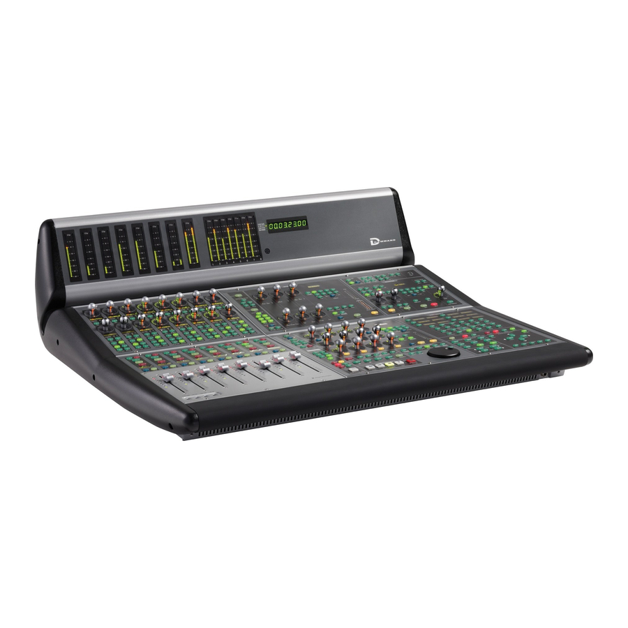
Soft Keys EQ Section section Session Management section Channel faders Zoom/Navigation Transport section Section Modifier keys Global Automation Mode Custom Fader Window Nudge/Bank controls controls controls Management section section Figure 1. D-Command Main Unit top panel Chapter 2: D-Command Overview 5... - Page 12 Meter Display Soft Keys Section The Meter display on the D-Command Main Unit can be set The Soft Keys section on the D-Command Main Unit provides to show the output levels, or levels associated with a track or access to a wide range of Pro Tools commands directly from plug-in.
- Page 13 Ethernet Connector The AC Power connector accepts a standard AC power cable. The Ethernet connector on the back panel of the D-Command The D-Command Main Unit is auto power-selecting (100V to Main Unit provides communication to Pro Tools. See “Ether- 240V) and automatically works with a standard modular net Connections”...
-
Page 14: D-Command Fader Module
The Power switch applies power to the Fader Module. Modifier Keys Ethernet Connector Each D-Command Fader Module has a set of four switches in its lower left corner that duplicate the function of the The Ethernet connector on the back panel of the D-Command Pro Tools computer keyboard modifiers. -
Page 15: D-Command Xmon Interface
D-Command XMON Interface D-Command monitoring is based on the XMON analog interface, which is remotely controlled from the D-Command monitoring section. XMON Front Panel XMON XMON Power switch Mute MIDI Receive indicator indicator Mute button Figure 4. XMON front panel... - Page 16 XMON Back Panel The back panel of the XMON interface includes connectors for all external analog audio inputs and outputs for D-Command. See “Audio Connections” on page 17. Cue Inputs Main Inputs Surround Inputs Stereo Inputs Cue Outputs Main Outputs...
-
Page 17: Part Ii Installation
Part II: Installation... -
Page 19: Chapter 3. Setting Up The Fader Module
Assembling an Expanded System • (10) 10-32 x 3/4-inch socket cap screw The D-Command Main Unit can be attached to the D-Com- • (4) 6-32 x 3/8-inch Philips pan head screw mand Fader Module, using the front, middle, and rear brack- ets included with the D-Command Fader Module. -
Page 20: Attaching The Units
Attaching the Units To attach the D-Command Fader Module to the Main Unit: Remove the plastic end cap from the left end of the Main Unit. Place the Fader Module to the left of the Main Unit, and press the D-Command units together. -
Page 21: Chapter 4. Connecting D-Command
D-Command units require power and Ethernet connections to operate with Pro Tools. An optional footswitch connection is also available on the Main Unit. The connectors on the back panel of the D-Command Main Unit are shown in Figure 5. Be sure to make all connections with your D-Command units and computer turned off. - Page 22 You can connect two SPST (single-pole, single-throw) foot- that can simultaneously support D-Command over 10-BaseT switch units to the D-Command Main Unit to control any of and other network traffic over 100-BaseT. This will let you use the following functions: D-Command over a local area network.
-
Page 23: Audio Connections
Figure 6. XMON back panel XMON Monitoring System Connection D-Command connects to XMON with a single 15-pin XMON cable. A 50-foot (15.25 m) cable is included with the D-Command Main Unit. The system supports up to an 80-foot (24.5 m) cable. -
Page 24: Control Room Monitoring Connections
• Listen Mic 2 (external), mic level (XMON provides 18V phantom power) Outputs • Main Control Room Outputs (6 channels), balanced or unbalanced, +4 dBu • Alt Control Room Outputs (6 channels), balanced or unbalanced, +4 dBu • Mini Control Room Outputs (2 channels), balanced or unbalanced, +4 dBu D-Command Guide... - Page 25 • External Talkback Mic, mic level (XMON provides 18V phantom power) Outputs • Cue 1 (2 channels), +4 dBu • Cue 2 (2 channels), +4 dBu • Headphone (2 channels), to internal headphone jack • Studio Loudspeaker (2 channels) • Talkback/Slate Output (1 channel) Chapter 4: Connecting D-Command 19...
- Page 26 D-Command Guide...
-
Page 27: Chapter 5. Configuring D-Command
Starting Up and Shutting Down the Software Configuration System All D-Command software is included when Pro Tools software is installed. The Pro Tools software installer places the D-Com- Your D-Command-based system must be started up and shut mand Personality folder on the system drive. -
Page 28: Setting D-Command Preferences
Naming D-Command Units in Pro Tools Press the Operation Console Prefs Soft Key switch twice to exit. You can set the names for D-Command units from Pro Tools. Custom Fader Justification To name D-Command units in Pro Tools: Choose Setup > Peripherals, and click Ethernet Controllers. - Page 29 Press the Operation Console Prefs Soft Key switch to exit. Faders On/Off The Faders On/Off preference lets you temporarily turn off D-Command faders to prevent fader movement when moni- toring a mix. To toggle D-Command faders on and off: Press the Operation switch in the Console Prefs Soft Keys section twice.
- Page 30 Insert or Send on-screen makes its track and off. Send levels are displayed on the LED rings surround- the focused track on the D-Command Main Unit. For details ing the D-Command rotary encoders. This metering follows on focusing a track on D-Command, see “Focusing a Track”...
-
Page 31: System Calibration
The Meters Pre/Post Fader preference toggles channel meter- ing between pre- and post-fader modes. Recalibrating D-Command Faders If a fader on a D-Command Unit shows response problems, To toggle channel meters between pre- and post-fader metering: you can recalibrate the faders with the Recal command in Press the Meters switch in the Console Prefs Soft Keys sec- Utility mode. - Page 32 D-Command Guide...
-
Page 33: Part Iii Reference
Part III: Reference... -
Page 35: Chapter 6. Channel Strip Controls
Rotary Encoder Section Channel Strips Each channel strip has two touch-sensitive rotary encoders The D-Command Main Unit has 8 channel strips, and the with LED ring, alphanumeric display, mode switches, and sta- D-Command Fader Module has 16 channel strips. Each chan- tus indicators. - Page 36 When assigning a send, the encoder Select switch is used to confirm the selection of the following: • Send type (interface or bus) • Send assignment When viewing a send, the encoder adjusts level. In Send Pan mode, the fader adjusts level and the encoder adjusts Pan. D-Command Guide...
- Page 37 When you press the Sends switch, you enter Sends mode, and the send names for the first two sends on that channel strip To open a plug-in window from any channel on D-Command: are displayed on the encoder displays. If there are additional Hold Start (Windows) or Control (Mac) and press the Select ■...
- Page 38 Channel Select switch MIDI Controls on Instrument Tracks Solo switch The Instruments View in Pro Tools contains MIDI controls Solo that can be displayed on the encoders of D-Command chan- Mute switch nel strips. Mute Channel display To display MIDI controls: Hold the Inserts switch and press the Sends switch in the ■...
- Page 39 Pro Tools Operation preference for latched operation. Fader Section Solo Safe Mode To solo safe a track from D-Command, hold Control (Windows) or Command (Mac) and press the track’s Solo switch. Mute Switch Automation Mode indicators The Mute switch toggles mute status for the channel.
- Page 40 Modifier Key Switches The touch-sensitive faders on D-Command channel strips Each D-Command Main Unit and Fader Module has a set of control channel volume in Normal mode, and a wide range of four switches in its lower left corner that duplicate the func- parameters in Flip mode or the Custom Fader modes.
-
Page 41: Global Controls Section
The two yellow Flip switches in the Global Controls section The Global Controls section (Figure 2) is a set of channel-re- correspond to the two rotary encoders on the D-Command lated controls in the center of the D-Command Main Unit. channel strips. Flip Mode... - Page 42 Send Pan Switch The Current switch writes a snapshot of the current parameter The Send Pan switch enables and suspends writing of send value to the currently displayed automation parameter. pan automation on all tracks in the session. D-Command Guide...
- Page 43 Show Values Switch multiple tracks in a Pro Tools session, and to change the dis- play mode of multiple channel strips on D-Command. The Show Values switch can follow toggling or momentary behavior. If pressed briefly, it toggles the encoder display be- The Do To All and Do To Selected switches can follow latching tween parameter name and parameter value.
- Page 44 Custom Fader mode). sion: • Channel Mute switch To change the display mode of D-Command channel strips: • Channel Solo switch Press the Do To All or the Do To Selected switch. • Channel Solo Safe: Control (Windows) or Command...
- Page 45 Bank/Cycle switch Press Set to Default + the Compare switch for the plug-in. ■ Bank / Cycle (The Compare switch appears in the D-Command Dynamics and EQ sections, and in Custom Fader Expanded Plug-in Custom Fader controls mode.) Focus Channel Display...
- Page 46 Automation Touch Automation Read the Custom Fader channels. Mode switch Mode switch Touch Read The Map switch has no effect on other D-Command channels Automation Latch Automation Off switch in Normal mode. Mode switch Latch Lock Switch Automation Mode controls The Lock switch applies to Custom Fader Plug-in mode only.
-
Page 47: Miscellaneous Controls
Touch Read when the selections are linked. Latch Edit/Timeline Switch and Indicators The Edit/Timeline switch toggles the D-Command transport Talkback switch function between the edit selection and the timeline selec- Talkback Dbl Press to Latch tion. The indicators above the switch light to show which is displayed. - Page 48 The Assign controls are used to assign inputs, outputs, inserts, channel encoders shows the sends on a channel. and sends to channels. Each switch puts D-Command into a temporary Assign mode in which elements are assigned or re- When assigning a send, the encoder Select switch is used to moved from channels.
- Page 49 To assign an input, output, send or insert: To assign a MIDI Input or Output on an Instrument track: Press an Assign switch to enter the corresponding Assign Press the Assign Inputs or Assign Outputs switch to enter mode. the corresponding Assign mode. Encoder row #1 shows MIDI inputs/outputs.
- Page 50 Safe button in the track’s on-screen output window. Plug-in Automation controls Press the Bypass/Mute/Pre switch for the plug-ins or sends for which you want to toggle automation safe status. Press the Automation Safe switch again to exit Automation Safe mode. D-Command Guide...
-
Page 51: Chapter 7. Plug-In Controls
first level of With D-Command, you can display, edit, and link specific menu choices. channels of multi-mono dynamics and EQ plug-ins directly... - Page 52 A plug-in is focused when its controls are mapped to the knobs, There are several ways to open plug-in windows on-screen switches or faders on D-Command. Its parameters can then be from D-Command. edited and automated from the control surface. D-Command...
- Page 53 Managing Multiple Plug-in Windows Making Plug-ins Inactive or Active D-Command lets you open and swap multiple plug-in win- You can toggle the active/inactive status of a plug-in directly dows on-screen. This makes it possible keep multiple plug-in from a channel strip without putting D-Command into Make windows open while focusing on different tracks (for exam- Inactive mode.
- Page 54 When plug-in names are displayed in top-level view on a Select the tracks containing the plug-ins you want to enable D-Command channel strip, you can quickly enable all param- for automation. eters of a plug-in for automation.
-
Page 55: Dynamics Section
Dynamics processing plug-ins may have widely varying con- The D-Command Dynamics section automatically focuses the trols, depending on their applications. The D-Command Dy- first dynamics plug-in on the channel displayed in the Focus namics Section provides dedicated knobs and switches to ac- Channel section on the Main Unit. - Page 56 The Auto indicator under the encoder knob lights when the displayed parameter is enabled for automation. D-Command Guide...
- Page 57 Gain/Hold and Threshold Controls Gain/Hold/Input Control The top encoder in this section controls the gain (make-up gain), the hold value for the current plug-in page, or the input gain for the current plug-in, depending on which indicator is Gain/Hold lit. The Auto indicator under the encoder knob lights when control the displayed parameter is enabled for automation.
- Page 58 Dynamics section, even flashes while the Save Settings dialog is open. when a different track is focused on D-Command. This switch lights when the plug-in focus is locked. Type a name for the plug-in setting.
- Page 59 • LFE havior. A maximum of six channels (5.1 surround) may be in use at In Select mode, if the D-Command Channel Window Display any time. preference is set to Yes, the Channel Select switches also change the channel display in the plug-in window.
- Page 60 The Compare switch toggles the Compare button in the plug-in window, which alternates between the currently Press the Automation switch again to exit Automation saved plug-in setting and any changes you have made. mode. D-Command Guide...
- Page 61 Cycle Switch Dynamics Gain Controls and Meters The Cycle switch steps through all available Dynamics plug-ins on the focused channel. Clip Indicator Master Bypass Switch The Master Bypass switch bypasses the plug-in. Page Switch Output meter With plug-ins that have more than one page of controls, the Page switch lights.
-
Page 62: Eq Section
Displaying EQ Plug-ins EQ processing plug-ins may have widely varying controls, de- The D-Command EQ section automatically displays the first pending on their applications. The D-Command EQ section EQ plug-in on the channel that is focused in the Focus Chan- uses paging to accommodate the widest range of plug-ins pos- nel section on the Main Unit. - Page 63 Low Filter and High-Pass Filter Controls Low-Mid Filter and Mid Filter Controls Q encoder Q encoder Notch/Shape switch Notch indicator Shelf indicator Frequency encoder Frequency encoder Low Filter High-Pass Filter Low-Mid Filter Mid Filter indicator indicator indicator indicator Gain Gain encoder encoder Filter In switch...
- Page 64 The bottom encoder controls the gain for each band. The Auto indicator under the encoder knob lights when the pa- rameter is enabled for automation. Filter In Switch The Filter In switch lets you engage or bypass the correspond- ing EQ band in the plug-in. D-Command Guide...
- Page 65 EQ section, even when a different When you are working with a multi-mono plug-in, the con- track is focused on D-Command. This switch lights when the trols for the channels are usually linked and edited together.
- Page 66 Multi-Mono Plug-ins When you are working with a multi-mono plug-in, the Master In Select mode, if the D-Command Channel Window Display Link switch toggles the Master Link button in the plug-in win- preference is set to Yes, the Channel Select switches also dow, which links or unlinks all channels of the plug-in.
- Page 67 EQ Edit and Display Controls Automation switch Automation Safe switch Clip indicator Window switch Output meter Compare switch Cycle switch Page switch Master Bypass switch Edit and Display controls in the EQ section Automation Switch Automation Safe Switch The Automation switch lets you enable EQ parameters for au- The Automation Safe switch toggles the Safe button in the tomation by touching or pressing their controls in the EQ sec- plug-in window, which protects existing automation for that...
- Page 68 D-Command Guide...
-
Page 69: Chapter 8. Transport And Navigation Controls
Chapter 8: Transport and Navigation Controls Transport Section The D-Command Transport section includes transport switches, switches for setting the transport mode, scrub/shuttle switches and controls, and advanced audition and locate switches. Transport Modes switches Audition switches Master Record Mode switch... - Page 70 When the Timeline and Edit selections in the Edit window are Scrub Switch unlinked, you can set the D-Command Transport to control playback of either the Timeline selection or the Edit selection. The Scrub switch places the transport in Scrub mode, which lets you scrub from the cursor position or across a selection.
- Page 71 Mark Out Switch Plays audio back-timed from the selection Machine Online Switch end by the pre-roll amount. This feature has not been implemented for D-Command. Post-Roll Switch Plays audio starting at the end of a selection through the post-roll amount.
- Page 72 Go To Start Switch The Go To Start switch returns the playback cursor to the be- ginning of the session. Go to End Switch The Go To End switch moves the playback cursor to the end of the session. D-Command Guide...
-
Page 73: Zoom/Navigate Section
■ Nudge/Bank Section The Nudge/Bank section controls the display of any channels in Normal mode on the D-Command surface. If any channels Zoom Preset switches are in any of the Custom Fader modes, they are not affected by D-Command Zoom/Navigate Section Bank or Nudge commands, and the other channels move around them. - Page 74 D-Command Guide...
-
Page 75: Chapter 9. Management Sections
Pan switch Memory Locations switch Edit switch Mix switch Plug-in switch D-Command Window Management section Workspace Browser Switch Transport Switch The Workspace Browser switch opens and closes the DigiBase The Transport switch opens and closes the Transport window Workspace Browser. Hold Alt (Windows) or Option (Mac) and Pan Switch press this switch to close all DigiBase windows. -
Page 76: Session Management Section
• To cancel the Save command, press Escape. Clear Clip Switch and Plug-in Clip Indicator Redo Switch D-Command indicates occurrences of signal clipping on au- dio tracks, sends, and plug-ins. (Clip indication on D-Com- The Redo switch executes the Redo command in Pro Tools. -
Page 77: Soft Keys Section
The Soft Keys section provides access to a wide range of Pro Tools commands directly from the control surface. It also provides access to preferences and settings specific to D-Command. The section consists of six variable-function soft keys and displays, along with a matrix of mode switches that change the functions shown in the displays. - Page 78 • Disk Alloc: Setup > Disk Allocation Management controls • Preferences: Setup > Preferences Snapshot Switch • Peripherals: Setup > Peripherals This function is currently not implemented for D-Command. Edit Controls Group Switch The Group switch displays the following commands: • Create Edit: Create Edit Groups •...
- Page 79 Edit Function 2 Switch Edit Tools Switch The Edit Function 2 switch displays the following commands: The Edit Tool Tools switch displays the Pro Tools Edit Tools. To cycle through multiple versions of the same tool, repeat- Page 1 edly press the corresponding Soft Key. •...
- Page 80 Meter Switch • Show Instmt: Show Only Instrument Tracks • Hide Instmt: Hide Only Instrument Tracks The Meter switch displays the following D-Command meter preferences: You can select multiple Show/Hide categories by holding Shift while pressing the corresponding Soft Key.
- Page 81 Global Controls section. D-Command Main Unit. When Focus Channel Strip is enabled, all controls and modes Faders (Faders On/Off) Turns off D-Command faders to pre- are linked. You can, however, use four encoders simulta- vent fader movement when monitoring a mix.
- Page 82 Automation Controls Modes Switch The Modes switch displays the following D-Command Modes: AWrtTo Start (Auto Write to Start on Stop) Automatically writes current automation values from the insertion point backward to the beginning of a selection or track when the transport is stopped after an automation pass.
- Page 83 Utility Switch Utility switch The Utility switch places the D-Command in Utility mode. When D-Command is in Utility mode, this switch flashes. Utility mode lets you view D-Command system information, name D-Command units, run D-Command diagnostic tests, and set certain D-Command hardware preferences. For com- plete information on Utility mode, see Appendix A, “Utility...
- Page 84 D-Command Guide...
-
Page 85: Chapter 10. Monitor And Meter Sections
The Monitor section includes a full set of controls for the control room monitoring, headphone/cue, and talkback/listenback sections of D-Command. All input and output connections to the D-Command monitoring system are made on the XMON in- terface, which is connected to the D-Command console with the XMON cable, and remotely controlled from this section. - Page 86 In normal operation, the Input Source switches follow exclu- sive-or (non-latching) behavior, allowing only one source to be monitored at a time. Sum switch Input source However, D-Command has a Sum mode that allows multiple Stereo Input switches Surround switches switch input sources to be monitored at the same time.
- Page 87 The following table shows possible outputs for each input Headphone/Cue Controls source. (Talkback can be added to each of the outputs.) Input Possible Outputs Studio Loudspeaker Headphones Cue 1 Cue 1, Headphone, Studio LS switch switch Cue 2 Cue 2, Headphone, Studio LS Cue Input Source switches Main Monitor...
- Page 88 • C (Center) • R (Right) • Ls (Left Surround) • Rs (Right Surround) • LFE These choices support all possible channel configurations in Pro Tools. A maximum of six channels (5.1 surround) may be in use at any time. D-Command Guide...
-
Page 89: Afl And Pfl Switches
To select the Solo mode: switch the Control Room Input source to monitor that path. Press the AFL or PFL switch in the D-Command Monitor sec- While in Broadcast mode, any channels soloed while in SIP tion to select the corresponding Solo mode. - Page 90 If rapidly double-pressed, the switch latches on and flashes to built-in (Internal) microphone, located on the meter bridge of indicate that talkback is active. Press the switch again to turn the D-Command Main Unit. off talkback. Talkback Dim Function When Talkback is engaged, the Dim switch lights and the Dim function is automatically applied to the Main outputs.
- Page 91 Listen Control To calibrate Control Room outputs to display SPL: Send the reference material to the Main Control Room Out- The Listen system has two selectable microphone inputs, both puts, and set the output level in Pro Tools to your studio ref- using the touch-sensitive rotary encoder for level control.
- Page 92 The Mute switch lights to indicate that it is active. If the Mute switch on the XMON interface front panel is acti- vated, the Mute switch on D-Command must be used to un- mute the monitor system. (Outputs cannot be unmuted from XMON front panel.)
-
Page 93: Meter And Time Code Displays (Main Unit)
The Channel Strip Meter display features dual 32-segment LED bar graphs for each channel, and can display pre- or post-fader levels depending on the D-Command Meter Preferences setting. In Custom Fader mode, these meter displays can show plug-in input and output meters, gain reduction meters for dynamics plug-ins, and other parameters. The top LED is red and indicates clipping on the corresponding channel or parameter. -
Page 94: Setting D-Command Meters For Different Reference Levels
Setting D-Command Meters for Different Reference Levels The Pro Tools Reference Level meter preference lets you change the D-Command meter display to help monitor program material with respect to different reference levels. At each setting except 0 dB, a single LED lights continuously across the meter bridge at a fixed point to indicate that reference level. -
Page 95: Chapter 11. Operating Modes
Chapter 11: Operating Modes The power and flexibility of D-Command lies in its different Press the flashing encoder Select switch or press the flashing operating modes, which let you customize the behavior of its Assign switch to confirm the assignments. - Page 96 To remove an input, output, send or insert: You can make Inputs, Outputs, Inserts, Sends, and entire tracks active or inactive directly from D-Command by enter- Press an Assign switch to enter the corresponding Assign ing a temporary Make Inactive mode.
- Page 97 Fader Plug-in mode. (See “Plug-In Mode” on page 97.) Inactive assignments are shown with an inverted text display. To focus a track in the Focus Channel section from D-Command: Repeat steps 2–3 to modify other send or insert assignments. Make sure the Select/Focus switch mode is set to Focus.
- Page 98 Press the Automation Safe switch. If the D-Command Focus Channel Strip Operations prefer- ence is set to Yes, focusing a track on D-Command brings the Press the channel Select switch on the tracks for which you name of the first active plug-in into the Focus Channel dis- want to toggle automation safe status.
- Page 99 You can set sends to pre-fader or post-fader operation directly Press the channel Select switch to move down and the chan- from D-Command, by setting the appropriate mode for the nel Mute switch to move up through menu levels. Bypass/Mute/Pre switch.
-
Page 100: Custom Fader Modes
Do one of the following: With the Custom Faders feature, you can temporarily set aside channel strips on D-Command and focus them on your own • To increase the maximum number of faders used by the customized groups of tracks, on Pro Tools Mix and Edit Custom Fader modes, press the Soft Key that corresponds groups, on specific track types, or on plug-in controls. - Page 101 Custom Groups are created and recalled entirely on D-Com- mand, and are independent of Mix/Edit groups in Pro Tools. To recall a Custom Group: D-Command Custom Groups are not reflected on-screen in Press the Groups switch in the Custom Faders section. Pro Tools.
- Page 102 Press the lit Tracks switch. ■ Press the Group switch in the Management Soft Key section. Choose the type of group to create: Edit Group, Mix Group, or Edit/Mix Group. Enter a name for the Group and click OK. D-Command Guide...
- Page 103 Plug-In Mode To enter Expanded Plug-In mode: Press and hold the Plug-In switch in the Custom Fader sec- ■ Plug-In mode focuses the first plug-in on the focused channel tion until the switch flashes. The plug-in header controls are on the Custom Fader Channels. This places all of the plug-in’s mapped as follows: parameters on the Custom Fader channel encoders, and any plug-in meters on the Custom Fader channel meters.
- Page 104 Plug-in mapping files (.pim) files can be imported and ex- ◆ Do one of the following: ported for use with other D-Command and D-Control con- soles. • Press the flashing Map switch to confirm the mapping. – or –...
- Page 105 Do one of the following: Exporting and Importing .pim Files • In the Custom Fader channels, touch any rotary encoder To export plug-in mapping: that you want to map to the selected channel’s fader. Press the Operation Console Prefs Soft Keys switch twice to –...
- Page 106 D-Command Guide...
-
Page 107: Entering Utility Mode
When the unit is in Utility mode, the Utility Setup Page is dis- A D-Command unit is online if Pro Tools is running and the played on the Soft Key displays (Main Unit) or on the bottom unit is declared in the Peripherals page of the Setups dialog. -
Page 108: Exiting Utility Mode
Exiting Utility Mode D-Command Name Page The Name page is used to view and change D-Command unit To exit Utility mode, do one of the following: names. These names appear in the Pro Tools Peripherals dia- Press the flashing Utility switch (Main Unit). -
Page 109: D-Command Test Pages
Press the Soft Key (Main Unit) or the encoder Select switch There are three test levels for Ethernet communication on (Fader Module) that corresponds to “Mendec.” D-Command: Internal, Mendec, and External. These tests can assist Digidesign Technical Support should you ever experi- To exit the Mendec Ethernet test: ence difficulty with Ethernet communication between Press the flashing Soft Key (Main Unit) or encoder Select... - Page 110 Press the Soft Key that corresponds to “Red,” “Yellow,” or ■ To exit Meter Bridge LED Test mode: “Green” to test all LEDs of the corresponding color. Press the Soft Key (Main Unit) or encoder Select switch ■ (Fader Module) that corresponds to “Escape.” D-Command Guide...
- Page 111 Press the Soft Key (Main Unit) or encoder Select switch ■ (Fader Module) that corresponds to “Escape.” In addition, under conditions of heavy use, the D-Command fader motor protection feature may disengage a fader if it is in danger of overheating. The Recal command reengages any dis- engaged faders.
-
Page 112: Resetting D-Command To Factory Defaults
Rotary Test Page D-Command Preferences The Rotary Test page lets you test the touch-sensitive encoder D-Command Preferences let you set various display and oper- knob and the LED ring in each rotary encoder, as well as the ation preferences for the unit. - Page 113 To set the display contrast: pressing the footswitch is the functional equivalent of press- ing the corresponding switch on the D-Command Main Unit. From the Preferences page, press the Soft Key (Main Unit) or the encoder Select switch (Fader Module) that corresponds to Each Footswitch Settings page has four options: “Contrast.”...
- Page 114 D-Command Guide...
-
Page 115: 25-Pin Female Connector Pinouts
Appendix B: Audio Connections and Pinouts All external D-Command audio connections are made to the back panel of the XMON interface, shown below. All audio con- nectors are standard female DB-25 connectors. The connector for communication with D-Command is a 15-pin female connec- tor. - Page 116 [Not Connected] * Main Speaker Outputs 2 and 4 are active on XMON, but Lc and Rc outputs cannot be controlled independently from the D-Command monitor section. Global Volume, Solo, and SHIELD GND connector housing Mute controls affect all outputs.
-
Page 117: 15-Pin Connector Pinouts
* Alt Speaker Outputs 2 and 4 are active on XMON, but Lc and Rc outputs cannot be controlled independently from the MIDI Output D-Command monitor section. Global Volume, Solo, and Headphones L Mute controls affect all outputs. Headphones R... - Page 118 D-Command Guide...
- Page 119 Index Numerics Automation Write controls 35 Write to All 36 9-Pin Remote switch 65 Write to All Enabled 36 Write to Current 36 Write to End 36 Write to Start 36 Actions switch (automation) 76 After-Fader Listen (Monitor section) 83 All Enabled switch (automation) 36 All Notes Off switch 70 B/M/P (see Bypass/Mute/Pre)
- Page 120 40 footswitch 7, 16 Custom Groups mode (Custom Fader) 39, 95 Footswitch settings 107 Cycle switch (plug-ins) 55, 61 Forward and Play 66 D-Command Units Gain/Hold/Input control 51 declaring 21 Global Controls 6, 35 naming 22 Global Modifier controls 37...
- Page 121 inputs (Monitor section) meters 6 main 80 calibration 25 selecting 80 plug-ins 61 stereo 80 reference levels 88 summing 80 Mic Pre mode 31 surround 80 Mic Select switches 85 trimming 80 Mid Filter controls (EQ plug-ins) 57 inserts MIDI controls 32 assigning 89, 93 MIDI switch 73 making inactive 90...
- Page 122 Auto Talkback switch 84 connections 4, 17, 109 Listen 85 operational 4 Mic Select switches 85 resetting D-Command units (Utility mode) 106 Talkback switch 84 rotary encoders 29 targeting plug-ins 47 automation mode indicator 30 Test pages (Utility mode) 103...
- Page 123 Undo switch 70 Unit Name (Utility mode) 102 User switch 74 Utility mode 101 Reset Unit 106 System Info 102 Test pages 103 Unit Name 102 Utility switch 77 Volume switch (automation) 36 Window Management switches 6, 69 Window switch (Custom Fader Plug-in mode) 40 Window switch (plug-ins) 54, 61 windows opening 69, 72...
- Page 124 D-Command Guide...
- Page 126 DIGIDESIGN TECHNICAL SUPPORT (USA) PRODUCT INFORMATION (USA) INTERNATIONAL OFFICES Visit our Digidesign Web site 2001 Junipero Serra Boulevard Tel: 650.731.6100 Tel: 800.333.2137 for contact information Daly City, CA 94014-3886 USA Fax: 650.731.6384 Tel: 650.731.6300 Fax: 650.731.6399...
Need help?
Do you have a question about the D-Command and is the answer not in the manual?
Questions and answers