Table of Contents
Advertisement
Safe Operation Practices • Set-Up • Operation • Maintenance • Service • Troubleshooting • Warranty
O
'
M
peratOr
s
anual
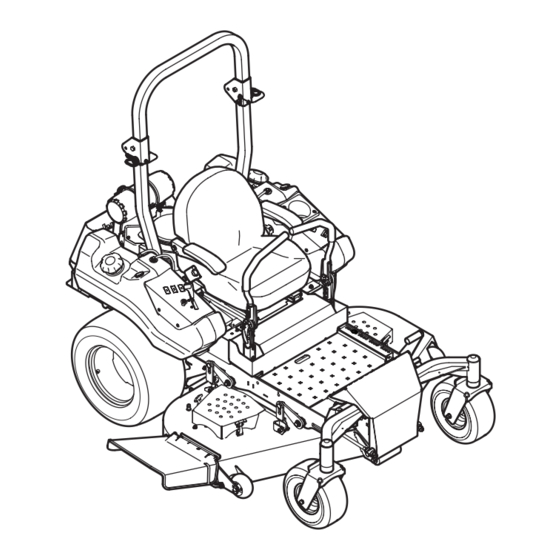
Tank LZ
WARNING
READ AND FOLLOW ALL SAFETY RULES AND INSTRUCTIONS IN THIS MANUAL
BEFORE ATTEMPTING TO OPERATE THIS MACHINE.
FAILURE TO COMPLY WITH THESE INSTRUCTIONS MAY RESULT IN PERSONAL INJURY.
CUB CADET LLC, P.O. BOX 361131 CLEVELAND, OHIO 44136-0019
Printed In USA
Form No. 769-07370
(February 23, 2012)
Advertisement
Table of Contents

Related Manuals for Cub Cadet TANK LZ 48


Summary of Contents for Cub Cadet TANK LZ 48
- Page 1 READ AND FOLLOW ALL SAFETY RULES AND INSTRUCTIONS IN THIS MANUAL BEFORE ATTEMPTING TO OPERATE THIS MACHINE. FAILURE TO COMPLY WITH THESE INSTRUCTIONS MAY RESULT IN PERSONAL INJURY. CUB CADET LLC, P.O. BOX 361131 CLEVELAND, OHIO 44136-0019 Printed In USA Form No. 769-07370...
-
Page 2: Table Of Contents
Visit us on the web at www.cubcadet.com See How-to Maintenance and Parts Installation Videos at www.cubcadet.com/tutorials ◊ Locate your nearest Cub Cadet Dealer at (877) 282-8684 ◊ Write to Cub Cadet LLC • P.O. Box 361131 • Cleveland, OH • 44136-0019... -
Page 3: Safe Operation Practices
Important Safe Operation Practices WARNING! This symbol points out important safety instructions which, if not followed, could endanger the personal safety and/or property of yourself and others. Read and follow all instructions in this manual before attempting to operate this machine. Failure to comply with these instructions may result in personal injury. -
Page 4: General Operation
Training Always wear appropriate clothing and personal protective equipment (e.g. safety glasses, long pants, gloves, hearing protection , safety shoes, hard hat) when operating or Read the Operator’s manual and other training material. If maintaining this machine. Long hair, loose fitting clothing the operator(s) or mechanic(s) cannot read English it is the or jewelry may get entangled in moving parts. - Page 5 Never attempt to operate the machine without the Keep all movements on the slopes slow and gradual. Do mowing deck attached; the machine could tip over. not make sudden changes in speed or direction. Rapid acceleration could cause the front of the machine to lift Keep the machine and especially the engine exhaust and rapidly flip over backwards, which could cause serious system and hydraulic components clean and free of grease,...
-
Page 6: Transporting Machines
Never allow children under 16 years of age to operate this Seat belts shall be used and shall be properly fastened machine. Children 16 and over should read and understand the about the operator’s waist at all times, except when the instructions and safe operation practices in this manual and on ROPS are: the machine and should be trained and supervised by an adult. - Page 7 Hydraulic Devices and Systems Never remove fuel cap or add fuel while the engine is hot or running. Allow engine to cool at least two Hydraulic fluid escaping under pressure may have sufficient minutes before refueling. force to penetrate skin and cause serious injury. If foreign fluid is Never over fill fuel tank.
- Page 8 Do not modify engine Grass catcher components and the discharge cover are subject to wear and damage which could expose moving To avoid serious injury or death, do not modify engine in any parts or allow objects to be thrown. For safety protection, way.
-
Page 9: Safety Symbols
Safety Symbols This page depicts and describes safety symbols that may appear on this product. Read, understand, and follow all instructions on the machine before attempting to assemble and operate. Symbol Description READ THE OPERATOR’S MANUAL(S) Read, understand, and follow all instructions in the manual(s) before attempting to assemble and operate WARNING—... - Page 10 2 — S ection peration racticeS...
-
Page 11: Assembly & Set-Up
Assembly & Set-Up Contents of Crate • One Zero-Turn Tractor • One ROPS Assembly • One Deck Wash Hose Coupler • One Zero-Turn Tractor Operator’s • One Engine Operator’s Manual Manual Tractor Preparation The two hydrostatic transmissions are equipped with a bypass valve that will allow you to manually move the NOTE: All references in this manual to the left or right side and tractor short distances. - Page 12 Install Roll Over Protective System (ROPS) Install the upper ROPS section onto the lower ROPS “posts”. Install the bolts and nuts. See Fig. 3-4. The Roll Over Protective System (ROPS) has not been installed on your unit for shipping purposes. Using the hardware found in the Roll Over Protective System container, install it on your unit Retaining as follows:...
- Page 13 Move the upper ROPS section to the upright position, and To adjust the height of the drive control levers: insert the locking pins with their retainer hairpin clips. See Remove the flange lock nuts that secure the carriage bolts Fig. 3-6. in the drive control levers.
- Page 14 Connecting the Battery Cables Seat Adjustment This tractor is equipped with an adjustable seat, which includes a CALIFORNIA PROPOSITION 65 WARNING retractable seat belt assembly and an Operator Presence Sensor Battery posts, terminals, and related accessories (OPS). The OPS in the form of a switch, is integrated into the seat contain lead and lead compounds, chemicals known bottom and is connected to the machine electrical system.
-
Page 15: Controls & Features
Controls & Features Deck Lift Pedal RH & LH Drive Control Levers Deck Height Index Seat Adjustment Lever Deck Lift Release Lever Parking Break Lever Digital Tachometer & Hour Meter Tool Box Throttle Control Ignition Switch Choke Knob PTO Switch Accessory Switch Receptacles Cup Holder Fuel Gauge... -
Page 16: Seat Adjustment Lever
Power Take-Off (PTO) Switch Parking Brake Lever The parking brake lever is located on the LH console to The PTO switch is located on the LH console the left of the operator’s seat. When pulled up it engages to the left of the operator’s seat next to the the parking brake and when pushed down it releases the ignition switch. - Page 17 Deck Lift Release Lever Accessory Switch Receptacles DECK AUX. LIGHTS LIFT The deck lift release lever is located on the left side of the The three receptacles for operator’s seat and is used to lock the deck in the transport optional accessories are position.
-
Page 18: Operation
It has been prepared to help you ever malfunction, do not operate the machine. Contact your operate and maintain your machine efficiently. authorized Cub Cadet Dealer. Fill the fuel tank with only clean, fresh, unleaded gasoline •... -
Page 19: Driving The Tractor
Practice Operation (Initial Use) Turn the ignition key clockwise to the START position and release it as soon as the engine starts; however, do not Operating a zero-turn tractor is not like operating a conventional crank the engine continuously for more than 10 seconds type riding tractor. - Page 20 Turning the Tractor While Driving Forward Move the throttle control lever forward to the full throttle (FAST) position. WARNING! When reversing the direction of travel, NOTE: Although the tractor’s engine is designed to run at we recommend performing gradual ‘U’ turns where full throttle, when performing a practice session the tractor possible.
- Page 21 Turning While Driving Rearward The greater the fore-to-aft distance between the two levers, the sharper the tractor will turn. To turn the tractor while driving rearward, move the control To execute a “pivot turn,” move the turn side drive control levers as necessary so that one lever is forward of the other.
- Page 22 Executing a Zero Turn Stopping the Tractor WARNING! Move both drive control levers to the neutral position to When executing a zero turn, the stop the motion of the machine. tractor MUST BE STOPPED. Executing a zero turn while the tractor is moving can significantly reduce Push the PTO down to the disengaged position.
- Page 23 Periodically check the safety interlock circuits to ensure they are working properly. If a safety circuit is not working as designed, contact you Cub Cadet dealer to have the tractor inspected. DO NOT operate the machine if any safety circuit is not functioning properly.
- Page 24 Mower Cutting Blades Low-lift — These blades require less horsepower than hi-lift and medium-lift blades, and they generally work best with wide The blades normally “factory installed” on a mower afford the best leaf grasses, sparse grass growth, and sandy soil conditions. grass cutting performance on the majority of grasses and mowing They generally produce the lowest noise levels.
-
Page 25: Maintenance & Adjustment
Maintenance & Adjustments Maintenance Schedule Before Every 25 Hours Every 50 Hours Every 500 Hours After Mowing Each use Check gasoline level Check tires & tire pressure Check deck, mower and hydro drive belts Check blades and blade bolt tightness Check safety switches for proper operation Check fluid level in transmission oil expansion reservoir Check engine intake screen/cover... - Page 26 OIL CHART Number of Oil Points Description DAILY Apply a few drops of SAE engine oil, grease, or use a spray lubricant. Apply Deck Suspension Pivots the oil to both sides of pivot points. Wipe Height Adjustment Turnbuckle Clevis Pin off any excess.
- Page 27 Periodically check the safety interlock circuits to ensure they are working properly. If a safety circuit is not working as designed, contact you Cub Cadet dealer to have the tractor inspected. DO NOT operate the tractor if any safety circuit is not functioning properly.
- Page 28 Battery Storage The wheel with the leaking tire should be inflated to 12 psi for the rear tire and 14 psi for the front tire . Then place the wheel in a When storing the tractor for extended periods, disconnect the large bucket of water.
- Page 29 Turn on the water supply. Remove the spark plugs and pour approximately one ounce of oil into each cylinder. Crank the engine one or From the tractor operator’s seat, start the engine and two turns to spread the oil evenly on the cylinder walls. engage the PTO.
- Page 30 Adjustments Front to Back Leveling Measure the blade-to-ground height at the right rear blade Seat tip. Again be sure to measure at the blade tip at the rear of the right blade when aligned along the mower centerline. Refer to the Assembly & Set-Up section for instructions on The blade-to-ground height at the rear of the blade tip adjusting the seat.
- Page 31 Brakes To lessen the tension on the belt loosen the flange lock nuts on the deck rods and then loosen the jam nuts until a ten-pound The parking brake handle should engage with moderate force. pull with a spring scale deflects the belt about 1⁄2”. Then re- The brake cable should not require adjustment, but if necessary tighten the flange lock nuts.
- Page 32 Removing/Installing the Inner Baffle The inner flow-control baffle can be removed depending on the mowing conditions. The baffle controls discharge and can be removed for high-volume grasses and installed for precision cutting. Remove the carriage bolts, push nuts and flange lock nuts that secure the baffle to the deck to mow high-volume grasses.
-
Page 33: Service
If you have a recurring problem with blown fuses, have the tractor’s Carefully lift the battery out of the tractor. electrical system checked by your Cub Cadet Service Dealer. Install the battery by repeating the above steps in the Safety Switch Operation Checks reverse order. -
Page 34: Deck Removal
Electric PTO Clutch Remove the four lynch pins that secure the deck to the deck lift assembly. See Fig. 7-3. This clutch operates when the engine is running, the operator is in the operator’s seat and the PTO is engaged. This electric clutch is a normally trouble free device. -
Page 35: Replacing The Blades
Replacing the PTO Belt Using a 1⁄2” drive insert the male end into the 1⁄2” square opening in the deck idler assembly and rotate the idler Remove the PTO belt from the deck as instructed in the clockwise on the 60” and 54” decks and counter-clockwise Deck Removal section then remove it from around the PTO on the 48”... - Page 36 Sharpening the Blades Wrap a rag around one end of the blade and grasp it to prevent it from turning, or secure the blade by placing a Set the parking brake. block of wood between the blade and the deck housing. See Fig.
- Page 37 Several components must be removed and special tools used in order to change the tractor’s transmission drive belt. See your Cub Cadet dealer to have the transmission drive belt replaced. Tractor Creeping Creeping is the slight forward or backward movement of the mower when the throttle is on and the speed control levers are in the neutral position.
-
Page 38: Troubleshooting
Troubleshooting Problem Cause Remedy Excessive vibration 1. Cutting blade loose or unbalanced. 1. Tighten blade and spindle. 2. Damaged or bent cutting blade. 2. Replace blade. Uneven cut 1. Deck not leveled properly. 1. Perform side-to-side deck adjustment. 2. Dull blade. 2. -
Page 39: Replacement Parts
Replacement Parts Component Part Number and Description 759-3336 Spark Plug Air Filter (LZ-48) KH-25-083-01-S Primary Air Filter (LZ-54 & LZ-60 w/ Kohler) KH-25-083-04-S Safety Air Filter (LZ-54 & LZ-60 w/ Kohler) Air Filter (LZ-60 w/ Kawasaki) Fuel Filter (LZ-48) KH-24-050-13-S Fuel Filter (LZ-54) KH-25-050-22-S1 Fuel Filter (LZ-60 w/Kohler) Fuel Filter (LZ-60 w/ Kawasaki) Oil Filter (LZ-48) - Page 40 Component Part Number and Description 634-3159 Deck Wheel 925-1707D Battery 751-12754 Gas Cap 946-04840 Throttle Control 946-04812 Choke Control 925-2054A Ignition Key 01006693P Discharge Chute Assembly 634-04749 Wheel Assembly (LZ-48), 24 x 9.5-12 634-04734 Wheel Assembly (LZ-54 & LZ-60), 24 x 12-12 02002821 Wheel Assembly, 13 x 6.50-6 10 —...
-
Page 41: Attachments & Accessories
Attachments & Accessories Part No. Part 59A30033150 Power Assist Triple Bagger 59A30036150 72” Snow Blade 59A30035150 Electric Deck Lift 490-850-0005 Blade Removal Tool 490-850-0008 Oil Siphon... - Page 42 FEDERAL and/or CALIFORNIA EMISSION CONTROL WARRANTY STATEMENT YOUR WARRANTY RIGHTS AND OBLIGATIONS MTD Consumer Group Inc, the United States Environmental Protection Agency (EPA), and, for those products certified for sale in the state of California, the California Air Resources Board (CARB) are pleased to explain the emission (evaporative and/or exhaust) control system (ECS) warranty on your outdoor 2006 and later small off-road spark-ignited engine and equipment (outdoor equipment engine) In California, new outdoor equipment engines must be designed, built and equipped to meet the State’s stringent anti-smog standards (in other states, 1997 and later model year equipment must be designed, built, and equipped to meet the U.S.
- Page 43 WARRANTED PARTS: The repair or replacement of any warranted part otherwise eligible for warranty coverage may be excluded from such warranty coverage if MTD Consumer Group Inc demonstrates that the outdoor equipment engine has been abused, neglected, or improperly maintained, and that such abuse, neglect, or improper mainte- nance was the direct cause of the need for repair or replacement of the part.
- Page 44 361131, Cleveland, Ohio 44136-0019, call 1-877-282- 8684 required maintenance and service intervals. or log on to our website at www.cubcadet.com. The limited warranty set forth below is given by Cub Cadet LLC with In Canada: respect to new merchandise purchased or leased and used in the Contact MTD Products Limited, Kitchener, ON N2G 4J1, call 1-800- 668-1238 or log on to our website at www.mtdcanada.com.