Table of Contents
Advertisement
Owner's Operator and Maintenance Manual
Portable Patient Lift and
Sling
DEALER: This manual MUST be given to
the user of the patient lift.
USER: BEFORE using this patient lift, read
this manual and save for future reference.
For more information regarding
Invacare products, parts, and services,
please visit www.invacare.com
Advertisement
Table of Contents

Related Manuals for Invacare 9805


Summary of Contents for Invacare 9805
- Page 1 Sling DEALER: This manual MUST be given to the user of the patient lift. USER: BEFORE using this patient lift, read this manual and save for future reference. For more information regarding Invacare products, parts, and services, please visit www.invacare.com...
- Page 2 WARNINGS, CAUTIONS AND INSTRUCTIONS, CONTACT INVACARE TECHNICAL SUPPORT BEFORE ATTEMPTING TO SERVICE OR OPERATE THIS EQUIPMENT - OTHERWISE, INJURY OR DAMAGE MAY RESULT. NOTE: Updated versions of this manual are available on www.invacare.com. Portable Patient Lift and Sling Part No 1024492...
-
Page 3: Table Of Contents
TABLE OF CONTENTS TABLE OF CONTENTS REGISTER YOUR PRODUCT ............... 4 LABEL LOCATION ................7 Models 9805 and 9805P..........................7 SPECIAL NOTES ................8 TYPICAL PRODUCT PARAMETERS ............ 9 SECTION 1—GENERAL GUIDELINES ..........10 Assembling the Lift ...........................10 Operating the Lift .............................10 Using the Sling ............................11... -
Page 4: Register Your Product
3. Receive updates with product information, maintenance tips, and industry news. 4. Invacare can contact you or your provider, if servicing is needed on your product. 5. It will enable Invacare to improve product designs based on your input and needs. - Page 5 11. User's Year of birth: ______________________________________________________ If at any time you wish not to receive future mailings from us, please contact us at Invacare Corporation, CRM Department, 39400 Taylor Parkway, Elyria, OH 44035, or fax to 877-619-7996 and we will remove you from our mailing list.
- Page 6 Fold here Fold here Invacare Product Registration Form Please Seal with Tape Before Mailing Portable Patient Lift and Sling Part No 1024492...
-
Page 7: Label Location
LABEL LOCATION LABEL LOCATION Models 9805 and 9805P WARNING WEIGHT CAPACITY is 450 lbs. The INVACARE Patient Lift is NOT a transport device. Moving a person suspended in a sling over ANY distance is NOT R E C O M M E N D E D . -
Page 8: Special Notes
Invacare products are specifically designed and manufactured for use in conjunction with Invacare accessories. Accessories designed by other manufacturers have not been tested by Invacare and are not recommended for use with Invacare products. Portable Patient Lift and Sling Part No 1024492... -
Page 9: Typical Product Parameters
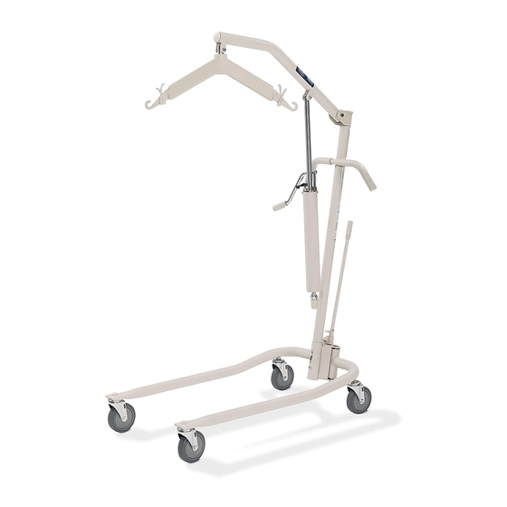
TYPICAL PRODUCT PARAMETERS TYPICAL PRODUCT PARAMETERS 9805 Hydraulic Adjustable Lift 9805P Hydraulic Adjustable Lift - Painted BASE (ONLY): 9884 9884P MAST (ONLY): 9800A BASE WIDTH OPEN: 42¼-inches 42¼-inches CLOSED: 22-inches 22-inches BASE HEIGHT: 6½-inches 6½-inches BASE LENGTH: 46¾-inches 46¾-inches BOOM HEIGHT AT SLING ATTACHMENT: MIN.:... -
Page 10: Section 1-General Guidelines
Check all parts for shipping damage before using. In case of damage, DO NOT use the equipment. Contact the Dealer for further instructions. The Invacare patient lift is not a transport device. It is intended to transfer an individual from one resting surface to another (such as a bed to a wheelchair). Moving a person suspended in a sling over any distance is not recommended. -
Page 11: Using The Sling
Adjustments for safety and comfort should be made before moving the patient. Patientʹs arms should be inside of the straps. Invacare slings are made specifically for use with Invacare Patient Lifts. For the safety of the patient, DO NOT intermix slings and patient lifts of different manufacturers. -
Page 12: Transferring The Patient
The pump is sealed at the factory. DO NOT attempt to open the pump or obtain local service as this will void the warranty and might result in damage. Consult your dealer or write Invacare for further information. After the first year of use, the hooks of the swivel bar and the mounting brackets of the boom should be inspected every three months to determine the extent of wear. -
Page 13: Section 2-Features
Slings attach to the lift by using either sewn-in loop straps, chains or adjustable straps. Slings are adjustable. They are interchangeable with any Invacare patient lift. Each sling offers reinforcing at each hook-on point to ensure patient safety. -
Page 14: Model Nos. 9042, 9043, 9046 And 9047 Slings
SECTION 2—FEATURES Invacare products are specifically designed and manufactured for use in conjunction with Invacare accessories. Accessories designed by other manufacturers have not been tested by Invacare and are not recommended for use with Invacare products. Model Nos. 9042, 9043, 9046 and 9047 Slings The one-piece contour sling can be used on heavy or light patients. -
Page 15: Section 3-Handling
NOTE: For this procedure, refer to FIGURE 3.1. NOTE: If the patient lift is to be reshipped by common carrier, it should be packed in the same carton. Extra cartons are available from Invacare. Unpacking 1. Check for any obvious damage to the carton or its contents. If damage is evident, notify Carrier/Invacare Dealer. -
Page 16: Section 4-Assembly
Assembly of the Patient Lift WARNING Use only Invacare parts in the assembly of this lift. The base legs, the mast, boom, pump assembly and the swivel bar are manufactured to specifications that assure correct alignment of all parts for safe functional operation. - Page 17 SECTION 4—ASSEMBLY 7. Remove the bolt and locknut from the top of the mounting bracket of the mast assembly. 8. Align the holes of the boom assembly and mast assembly mounting bracket. Insert the bolt completely through the holes of the mast assembly mounting bracket and the boom assembly.
-
Page 18: Base Shifter Handle Assembly
SECTION 4—ASSEMBLY Base Shifter Handle Assembly NOTE: For this procedure, refer to Base Shifter Handle FIGURE 4.3. 1. Insert the base shifter handle into the cam lock assembly at the back of the base. Thumbscrew Cam Lock 2. Align the holes of the shifter handle Assembly and cam lock assembly. -
Page 19: Section 5-One-Piece Contour Slings
Slings Using Chains, O-rings and D-rings WARNING Invacare slings are designed specifically for use with Invacare Patient Lifts and made to support the patient during lift and transfer procedures. Slings attach to the lift with either straps or chains (interchangeable). The slings are reinforced at all points of attachment for safety. -
Page 20: Positioning The Contour Sling
SECTION 5—ONE-PIECE CONTOUR SLINGS Positioning the Contour Sling NOTE: For this procedure, refer to FIGURE 5.1. 1. Position the patient in the center of the bed and laying flat on his/her back. 2. Fold the sling in half (length-wise) and place the fabric sections of the sling beside the patient. -
Page 21: Positioning The Patient On The Sling
1. If the patient is to roll to their left-side, then elevate the patient’s right knee until the right foot is flat on the bed (Detail “B” of FIGURE 5.1). NOTE: Invacare recommends that two assistants (one on each side of the bed) be used when positioning the patient in a sling. - Page 22 SECTION 5—ONE-PIECE CONTOUR SLINGS DETAIL “A” - POSITIONING DETAIL “B” - ROLLING PATIENT TO SIDE Patient Centered in Sling DETAIL “C” - ROLLING PATIENT BACK FIGURE 5.2 Positioning the Patient on the Sling Portable Patient Lift and Sling Part No 1024492...
-
Page 23: Section 6-Attaching Sling Hardware
SECTION 6—ATTACHING SLING HARDWARE SECTION 6—ATTACHING SLING HARDWARE Attaching the Sling Hardware The hardware used with the one-piece contour sling includes four metal support bars. The hardware inserts into the pockets at the edge of the fabric. The pocket that will hold the metal bar has an opening in the center. -
Page 24: Attaching The Chains Or Adjustable Straps To The Sling
SECTION 6—ATTACHING SLING HARDWARE DETAIL DETAIL “A” “B” Strap Over Metal Support Bar Metal Support Bars with Openings for Chains or Straps DETAIL “C” FIGURE 6.1 Inserting the Four Metal Support Bars into the Sling Attaching the Chains or Adjustable Straps to the Sling CAUTION When using either the chains or straps to connect the sling to the patient lift, the short- est of the two sections of the chains or straps MUST be attached to the back section of... -
Page 25: Part No 1024492 Portable Patient Lift And Sling
SECTION 6—ATTACHING SLING HARDWARE WARNING When changing to different lengths, DO NOT disconnect the O-rings of the chains from the swivel bar. Position both the O-rings and additional chain link onto the hooks of the swivel bar. NOTE: The straps can be simply adjusted to achieve the same effect. 4. -
Page 26: Section 7-Operation
SECTION 7—OPERATION SECTION 7—OPERATION Operating the Patient Lift Opening the Legs of the Adjustable Base WARNING The operation of the patient lift is an easy and safe procedure. DO NOT attempt any transfer without approval of the patient’s physician, nurse or medical assistant. Thoroughly read the instructions in this Owner’s Manual, observe a trained team of experts performing the lifting procedures and then perform the entire lift procedure several times with proper supervision and a capable individual acting as a patient. -
Page 27: Raising/Lowering Model Hydraulic Lifts
SECTION 7—OPERATION DETAIL “A” Base Closed Base Open Shifter Shifter Handle Handle Locked DETAIL “B” Step 1 Step 2 Step 3 FIGURE 7.1 Operating the Patient Lift - Opening the Legs of the Adjustable Base Raising/Lowering Model Hydraulic Lifts NOTE: For this procedure, refer to FIGURE 7.2 on page 28. There are two controls on the pump assembly: 1. -
Page 28: Lowering The Lift
SECTION 7—OPERATION Lowering the Lift The control handle MUST be in the open position (control valve positioned away from pump handle) to lower the boom and the patient. The rate of descent can be controlled by varying the amount that the control valve is opened. NOTE: A safety gate is part of the hydraulic system that maintains a SLOW constant descent of the boom regardless of how far the control valve is opened. -
Page 29: Section 8-Lifting The Patient
SECTION 8—LIFTING THE PATIENT SECTION 8—LIFTING THE PATIENT WARNING Before lifting or transferring the patient, the base legs MUST be locked in the open position for optimum stability and safety. Refer to General Guidelines on page 10 before proceeding further and observe all WARNINGS indicated. - Page 30 Adjustments for safety and comfort should be made before moving the patient. Patient’s arms should be inside of the chains or straps. Invacare slings and hardware are made specifically for use with Invacare Patient Lifts. For the safety of the patient, DO NOT intermix slings and patient lifts of dif- ferent manufacturers.
- Page 31 SECTION 8—LIFTING THE PATIENT 7. Using the steering handles, move the patient lift away from the bed. 8. When moving the patient lift away from the bed, turn patient so that he/she faces assistant operating the patient lift (FIGURE 8.4). 9.
-
Page 32: Section 9-Bathroom
NOTE: The slings with commode openings are designed to be used with either a commode chair or standard commode. NOTE: Invacare recommends that the sling remain connected to the swivel bar during the patient’s use of either the commode chair or standard commode. -
Page 33: Transferring To A Standard Commode
SECTION 9—BATHROOM DETAIL “A” - GUIDING THE PATIENT DETAIL “B” - LOWERING THE PATIENT Commode Commode FIGURE 9.1 Transferring to a Commode Chair Transferring to a Standard Commode NOTE: For this procedure, refer to FIGURE 9.1. NOTE: The patient MUST be transferred to a wheelchair and transported to the bathroom facilities before using the patient lift again to position the patient on a standard commode. -
Page 34: Bathing
Adjustments for safety and comfort should be made before moving the patient. Patient's arms should be inside of the chains or straps. Invacare slings and hardware are made specifically for use with Invacare Patient Lifts. For the safety of the patient, DO NOT intermix slings and patient lifts of dif- ferent manufacturers. -
Page 35: Section 10-Transferring
NOTE: For this procedure, refer to FIGURE 10.1 on page 36. NOTE: Invacare recommends that two assistants be used when transferring a patient to a wheelchair. 1. Ensure the legs of the lift (w/patient) are in the opened position. - Page 36 SECTION 10—TRANSFERRING DETAIL “A” - LOCKING REAR WHEELS Wheel Lock DETAIL “B” - GUIDING THE PATIENT Back Seat Sling Handle DETAIL “C” - (hidden from view) SETTING THE PATIENT Sling Side FIGURE 10.1 Transferring to a Wheelchair Portable Patient Lift and Sling Part No 1024492...
-
Page 37: Transferring To A Car
NOTE: To position an individual in a sling, follow the procedures concerning lifting the patient, operation and sling attachments. NOTE: Invacare recommends that two assistants be used when transferring a patient from a wheelchair to a car. NOTE: The transfer to a car should be made on a level driveway or surface. - Page 38 SECTION 10—TRANSFERRING 9. If necessary, remove the mast, boom and pump assembly from the base and transport them in the car. NOTE: If the lift and wheelchair are both packed in the trunk of the car, care should be taken not to damage the spokes of the wheelchair on the steering handles of the lift.
-
Page 39: Transferring From A Car To A Wheelchair
Warranty will be voided. NOTE: For this procedure, refer to FIGURE 10.3 on page 40. NOTE: Invacare recommends that two assistants be used when transferring a patient from a car to a wheelchair. NOTE: One assistant MUST support patient at all times. - Page 40 SECTION 10—TRANSFERRING DETAIL “A” - ATTACHING THE CHAINS Sling Chain First Asssitant DETAIL “B” - Patient REMOVING THE Lift PATIENT FROM THE CAR Second Assistant FIGURE 10.3 Transferring from a Car to a Wheelchair Portable Patient Lift and Sling Part No 1024492...
-
Page 41: Section 11-Care And Maintenance
The Invacare Patient Lift is designed to provide a maximum of safe, efficient and satisfactory service with minimum care and maintenance. All parts of the Invacare Lift are made of the best grades of steel, but metal to metal contact will wear after considerable use. -
Page 42: Wear And Damage
SECTION 11—CARE AND MAINTENANCE Lubricate all pivot points. Wipe all excess lubricant from lift surface. 1. Swivel Bar at Mounting Bracket 2. Boom Mounting Bracket 3. Boom to Mast Mount 4. Mast Mounting Bracket 5. Base to Mast Mount 6. Rear Casters 7. -
Page 43: Maintenance Safety Inspection Checklist
SECTION 11—CARE AND MAINTENANCE Maintenance Safety Inspection Checklist ITEM INITIALLY INSTITU- IN-HOME IN-HOME TIONAL INSPECT/ INSPECT/ INSPECT/ ADJUST ADJUST ADJUST EVERY SIX MONTHLY MONTHLY MONTHS CASTER BASE Inspect for missing hardware. Lift Base opens/closes with ease. Inspect roll pin to ensure secure base. Inspect casters and axle bolts for tightness. -
Page 44: Limited Warranty
If within such warranty period any such product shall be proven to be defective, such product shall be repaired or replaced, at Invacare’s option. This warranty does not include any labor or shipping charges incurred in replacement part installation or repair of any such product.
Need help?
Do you have a question about the 9805 and is the answer not in the manual?
Questions and answers