
Related Manuals for GE Zenith Controls ZTX


Summary of Contents for GE Zenith Controls ZTX
- Page 1 -10 0 0 9/05 GE Zenith Controls X Series Automatic Transfer Switches 40-400 Amps Operation and Maintenance Manual...
-
Page 2: Table Of Contents
Introduction GE Zenith Transfer Switches are used to provide a continuous source of power for lighting and other critical loads by auto- matically transferring from source 1 power to source 2 power in the event that source 1 voltage falls below preset limits. -
Page 3: Power Connections
(Can Cause Severe Injury or Death) Turn OFF all power before installation, adjustment, or removal of transfer switch or any of its components. The safe operation of your switch is GE Zenith’s focus. The proper storage, installation, operation and mainte- nance will help increase the life of the switch. -
Page 4: Power Connections
Turn OFF all power before installation, adjustment, or removal of transfer switch or any of its components. Power Connections GE Zenith transfer switches are supplied with UL listed solderless screw type terminals as standard for the Normal, Emergency and Load power connections. -
Page 5: Control Connections
Socket Size Across Flats 5/32 3/16 7/32 5/16 9/16 Table 2 HZ - PHASE - ZTX Operation and Maintenance Manual (72 R -1000) Note: N = Utility Position E = Generator Position Torque Lb. - In. Lb. - Ft. ■ ■... -
Page 6: Exerciser Option
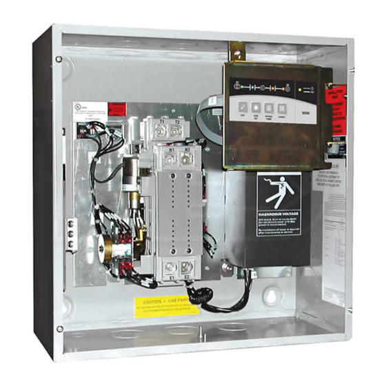
If the battery is not Battery and Holder Battery Harness MX60 Controller (Under Cover) ■ ■ ZTX Operation and Maintenance Manual (72 R -1000) (cont’d) DANGER HAZARDOUS VOLTAGE installed and/or replaced as recommended, an exerciser set from the front panel will lose its settings during power outages and the exerciser will not work. -
Page 7: Functional Test
S2 Restore Frequency Timers W Timer T Timer W - 20 sec. T - 5 min. ZTX Operation and Maintenance Manual (72 R -1000) T Timer U Timer T - 5 min. U - 5 min. Time Delay Time Delay... -
Page 8: Jumper Positions
ZTX control boards are capable of being adjusted slightly, to meet different source characteristics for voltage as well as frequency. (See Table 5) -
Page 9: Control Interface
EXER SET - Sets an Automatic Exerciser BYPASS TIMER - Pressed while E is blinking bypasses any remaining countdown Timer CANCEL - Depending on the current state of ATS operation, ends specific functions or indications ZTX Operation and Maintenance Manual (72 R -1000) ■ ■... -
Page 10: Using The Keypad Controls
Load will be transferred back to S1, after T- time, ending by running the U-time and finally ending the call for S2. ■ ■ ZTX Operation and Maintenance Manual (72 R -1000) (cont’d) DANGER HAZARDOUS VOLTAGE TIMER BYPASS This key is used to bypass (truncate), any of the running timers shown in Table 3. -
Page 11: Automatic Generator Exerciser
Turn OFF all power before installation, adjustment, or removal of transfer switch or any of its components. Automatic Generator Exerciser The ZTX automatic generator Exerciser can perform a pre-scheduled repeating test of the generator and/or the ATS mechanism depending on which jumpers are selected on the controller board. -
Page 12: In-Phase Monitor
Turn OFF all power before installation, adjustment, or removal of transfer switch or any of its components. In-Phase Monitor ZTX ATS senses when the sources are as far out as 2 Hz or as close as .01Hz in frequency differential of each other and transfers the load to and from either source in-phase. -
Page 13: Example Systems
■ ■ GE Zenith Controls Figure 9 Transfer Switch Loads Figure 10 Transfer Switch Circuit Breaker Main Breaker Panel ZTX Operation and Maintenance Manual (72 R -1000) Generator Source Circuit Breaker Loads Distribution Panel Generator Source All Loads ■ ■... -
Page 14: Typical Diagrams
Typical Diagrams Power Circuit Schematic 40-240 Amps Power Panel Layout ■ ■ ZTX Operation and Maintenance Manual (72 R -1000) Interconnect Plug OPTIONAL 3 Figure 12 Figure 11 SCOM Figure 13 GE Zenith Controls ■ ■... -
Page 15: Replacement Parts
Coil Cutout Switch Rectifier A3/A4 Auxiliary Contacts ■ ■ GE Zenith Controls VOLTAGE 380/416 440/480 120-480V 600V ZTX Operation and Maintenance Manual (72 R -1000) Figure 14 40 TO 200 AMPS K-2207 K-2208 K-2208 K-2228 K-2212 K-2209 57P-1030 L-3078 L-4027... -
Page 16: Standard Transition 225-400 Amps
T 1,2,3 N CN/CE Solenoid SN/SE Position Sense Limit Switch A3/A4 Auxiliary Contacts Rectifier ■ ■ ZTX Operation and Maintenance Manual (72 R -1000) (cont’d) N1 N2 N3 NN Stock Numbers by Amperage Recommended as Spares 225, 250* S-2701 #6-250 MCM... -
Page 17: Troubleshooting
SN limit switch bad or intermittent SE Limit switch bad or intermittent Solenoid bad or disconnected ATS contactor in mid-position ZTX Operation and Maintenance Manual (72 R -1000) Corrective Action Check for under voltage Check for missing phase (s) Check for under frequency... - Page 18 GE Zenith Controls A Product of GE Consumer & Industrial General Electric Company 830 West 40 Street, Chicago, IL 60609 773 299-6600 , Fax: 773 247-7805 www.geelectrical.com...
Need help?
Do you have a question about the ZTX and is the answer not in the manual?
Questions and answers