Table of Contents
Advertisement
Quick Links
Advertisement
Table of Contents

Related Manuals for Miller S-74 Boom w/Drive


Summary of Contents for Miller S-74 Boom w/Drive
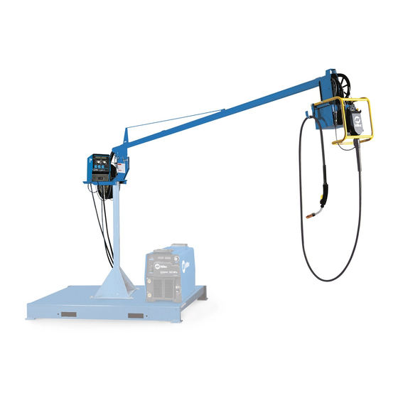
- Page 1 OM-252 045B 2011−10 Processes MIG (GMAW) Welding Flux Cored (FCAW) Welding (Gas-and Self-Shielding) Submerged (SAW) Welding Description Boom w/drive S-74 Boom w/Drive 8 ft, 12 ft, and 16 ft File: MIG (GMAW) Visit our website at www.MillerWelds.com...
- Page 2 ISO 9001:2000 Quality System Standard. particular model are also provided. Miller Electric manufactures a full line of welders and welding related equipment. For information on other quality Miller products, contact your local Miller distributor to receive the latest full line catalog or individual specification sheets.
-
Page 3: Table Of Contents
TABLE OF CONTENTS SECTION 1 − SAFETY PRECAUTIONS - READ BEFORE USING ........1-1. -
Page 5: Section 1 − Safety Precautions - Read Before Using
SECTION 1 − SAFETY PRECAUTIONS - READ BEFORE USING som 2011−01 Protect yourself and others from injury — read and follow these precautions. 1-1. Symbol Usage DANGER! − Indicates a hazardous situation which, if Indicates special instructions. not avoided, will result in death or serious injury. The possible hazards are shown in the adjoining symbols or explained in the text. - Page 6 D Remove stick electrode from holder or cut off welding wire at FUMES AND GASES can be hazardous. contact tip when not in use. D Wear oil-free protective garments such as leather gloves, heavy Welding produces fumes and gases. Breathing shirt, cuffless trousers, high shoes, and a cap.
-
Page 7: Additional Symbols For Installation, Operation, And Maintenance
1-3. Additional Symbols For Installation, Operation, And Maintenance FIRE OR EXPLOSION hazard. MOVING PARTS can injure. D Do not install or place unit on, over, or near D Keep away from moving parts such as fans. combustible surfaces. D Keep all doors, panels, covers, and guards D Do not install unit near flammables. -
Page 8: California Proposition 65 Warnings
1-4. California Proposition 65 Warnings For Gasoline Engines: Welding or cutting equipment produces fumes or gases which contain chemicals known to the State of California to Engine exhaust contains chemicals known to the State of cause birth defects and, in some cases, cancer. (California California to cause cancer, birth defects, or other reproduc- Health &... -
Page 9: Section 2 − Consignes De Sécurité − Lire Avant Utilisation
SECTION 2 − CONSIGNES DE SÉCURITÉ − LIRE AVANT UTILISATION fre_som_2011−01 Se protéger et protéger les autres contre le risque de blessure — lire et respecter ces consignes. 2-1. Symboles utilisés DANGER! − Indique une situation dangereuse qui si on Indique des instructions spécifiques. - Page 10 Il reste une TENSION DC NON NÉGLIGEABLE dans LE SOUDAGE peut provoquer un les sources de soudage onduleur UNE FOIS incendie ou une explosion. l’alimentation coupée. Le soudage effectué sur des conteneurs fermés tels D Arrêter les convertisseurs, débrancher le courant électrique et que des réservoirs, tambours ou des conduites peut décharger les condensateurs d’alimentation selon les instructions provoquer leur éclatement.
-
Page 11: Dangers Supplémentaires En Relation Avec L'installation, Le Fonctionnement Et La Maintenance
ACCUMULATIONS LES BOUTEILLES peuvent exploser risquent de provoquer des blessures si elles sont endommagées. ou même la mort. Les bouteilles de gaz comprimé contiennent du gaz D Fermer l’alimentation du gaz comprimé en cas sous haute pression. Si une bouteille est endommagée, elle peut exploser. -
Page 12: Proposition Californienne 65 Avertissements
Les PIÈCES MOBILES peuvent RAYONNEMENT HAUTE causer des blessures. FRÉQUENCE (H.F.) risque provoquer des interférences. D Ne pas s’approcher des organes mobiles. D Ne pas s’approcher des points de coincement D Le rayonnement haute fréquence (H.F.) peut tels que des rouleaux de commande. provoquer des interférences avec les équi- pements de radio−navigation et de com- munication, les services de sécurité... -
Page 13: Principales Normes De Sécurité
2-5. Principales normes de sécurité Safety in Welding, Cutting, and Allied Processes, ANSI Standard Z49.1, 25 West 43rd Street, New York, NY 10036 (téléphone : 212-642-4900, de Global Engineering Documents (téléphone : 1-877-413-5184, site site Internet : www.ansi.org). Internet : www.global.ihs.com). Standard for Fire Prevention During Welding, Cutting, and Other Hot Safe Practices for the Preparation of Containers and Piping for Welding Work, NFPA Standard 51B, de National Fire Protection Association,... - Page 14 OM-252 045 Page 10...
-
Page 15: Section 3 − Introduction
SECTION 3 − INTRODUCTION 3-1. Specifications Type of Input Welding Power Wire Diameter Welding Circuit Wire Feed Speed Range Weight Power Source Type Range Rating Standard: 50 To 780 ipm .023 To 5/64 in. (0.6 12 ft (3.7 m): 100 Volts, 24 Volts AC Constant Voltage (CV) (1.3 To 19.8 mpm) -
Page 16: Adjusting Control Tilt Bracket
4-3. Adjusting Control Tilt Bracket Tilt Bracket Rear Pivot Screw Front Screw Loosen rear pivot screw. Remove front screw. Pivot control down- ward to desired viewing angle. Re- place and tighten front screw. Tight- en pivot screw. 805 413-A 4-4. Installing Boom And Reel Support Swivel Plates Yoke Remove hardware from swivel... -
Page 17: Installing Wire Guide Extension
4-5. Installing Wire Guide Extension Wire Guide Fitting Bolt Monocoil Liner Wire Guide Extension Tighten bolt to secure liner in wire guide fitting. Do not overtighten bolt and crush liner. Tools Needed: 3/8 in. 152 323-B 4-6. Equipment Connection Diagram Welding Power Source Remote 14 Connection Positive (+) Weld Output... -
Page 18: Control Box Connections
4-7. Control Box Connections Interconnecting Cable Receptacle Interconnecting Cable 14-Pin Receptacle Ref. 805 415-B 4-8. 14-Pin Plug Information Pin* Pin Information 24 volts AC with respect to socket G. Contact closure to A completes 24 volts AC contactor control circuit. Circuit common for 24 volts AC circuit. -
Page 19: Removing Safety Collar And Adjusting Boom
4-9. Removing Safety Collar And Adjusting Boom Locking Knob Tighten knob to prevent boom movement. Loosen knob to allow boom movement. Change knob po- sition to limit upward movement. Pull boom down slightly and remove safety collar. Boom should balance in any position from horizontal to 60 degrees above horizontal. -
Page 20: Installing And Threading Welding Wire
4-11. Installing And Threading Welding Wire Tools Needed: 15/16, 3/8 in. 3/16, 5/64 in. Install wire spool. Ad- just tension nut so wire is taut when wire feed stops. Pressure Adjust Pressure Indicator Scale Install wire guide. Pressure Adjust Drive Rolls Install drive rolls. -
Page 21: Section 5 − Maintenance
SECTION 5 − MAINTENANCE 5-1. Routine Maintenance Disconnect power before maintaining. 3 Months Clean and Repair or tighten Replace replace weld unreadable cracked terminals. labels. weld cable. Replace Check Check gas Check gun cracked 14-pin cord. hose and cable. parts. fittings. -
Page 22: Section 6 − Parts List
SECTION 6 − PARTS LIST Hardware is common and not available unless listed. 805 419-C Figure 6-1. Main Assembly OM-252 045 Page 18... - Page 23 Quantity Model Item Dia. Part Mkgs. Description Figure 6-1. Main Assembly ....201 319 Cable, Interconnecting (Includes) ..... .
- Page 24 21 22 Hardware is common and not available unless listed. 142 601-H Figure 6-2. Boom Assembly OM-252 045 Page 20...
- Page 25 Quantity Model Item Part Description Figure 6-2. Boom Assembly (Figure 6-1 Item 11) ..000 527 Plug, 0.875 Inch ..........
- Page 26 Hardware is common and not available unless listed. See Table 6-1 For Drive Roll & Wire Guide Kits 802 977-B Figure 6-3. Drive Assembly, Wire OM-252 045 Page 22...
- Page 27 Item Dia. Part Mkgs. Description Quantity Figure 6-3. Drive Assembly, Wire (Figure 6-1 Item 26) ....010 668 Screw, Cap Stl Sch .250-20 X 1.500 .
- Page 28 Hardware is common and not available unless listed. *Includes Item 8 146 339-B Figure 6-4. Support, Hub & Reel Item Part Description Quantity Figure 6-4. Support, Hub & Reel (Figure 6-1 Item 9) ... . 142 399 Support, Reel .
- Page 29 Table 6-1. Drive Roll And Wire Guide Kits OM-252 045 Page 25...
- Page 30 Notes OM-252 045 Page 26...
- Page 31 LIMITED WARRANTY − Subject to the terms and conditions 90 Days — Parts Call below, Miller Electric Mfg. Co., Appleton, Wisconsin, warrants to its Accessory (Kits) 1-800-4-A-MILLER original retail purchaser that new Miller equipment sold after the...
- Page 32 Contact the Delivering Carrier to: File a claim for loss or damage during shipment. For assistance in filing or settling claims, contact your distributor and/or equipment manufacturer’s Transportation Department. ORIGINAL INSTRUCTIONS − PRINTED IN USA 2011 Miller Electric Mfg. Co. 2011−01...
Need help?
Do you have a question about the S-74 Boom w/Drive and is the answer not in the manual?
Questions and answers