
Related Manuals for Miller Electric Millermatic 212 Auto-Set


Summary of Contents for Miller Electric Millermatic 212 Auto-Set
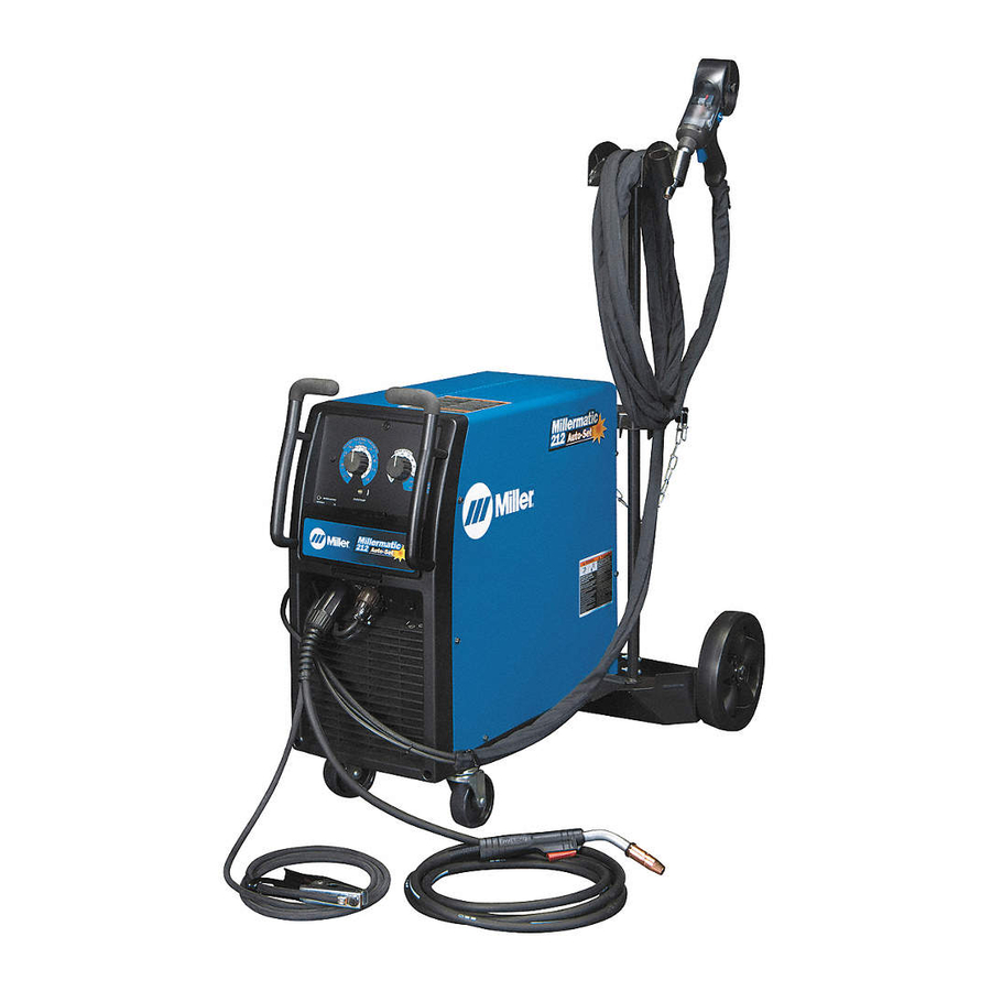
- Page 1 OM-238 118F 2012−01 Processes MIG (GMAW) Welding Flux Cored (FCAW) Welding Description Arc Welding Power Source and Wire Feeder Millermatic 212 Auto-Set File: MIG (GMAW) Visit our website at www.MillerWelds.com...
- Page 2 ISO 9001 Quality System Standard. particular model are also provided. Miller Electric manufactures a full line of welders and welding related equipment. For information on other quality Miller products, contact your local Miller distributor to receive the latest full line catalog or individual specification sheets.
-
Page 3: Table Of Contents
TABLE OF CONTENTS SECTION 1 − SAFETY PRECAUTIONS - READ BEFORE USING ....... . . 1-1. - Page 4 TABLE OF CONTENTS SECTION 8 − MIG WELDING (GMAW) GUIDELINES ..........8-1.
-
Page 5: Section 1 − Safety Precautions - Read Before Using
SECTION 1 − SAFETY PRECAUTIONS - READ BEFORE USING som 2011−10 Protect yourself and others from injury — read, follow, and save these important safety precautions and operating instructions. 1-1. Symbol Usage DANGER! − Indicates a hazardous situation which, if Indicates special instructions. - Page 6 D Remove stick electrode from holder or cut off welding wire at FUMES AND GASES can be hazardous. contact tip when not in use. D Wear oil-free protective garments such as leather gloves, heavy Welding produces fumes and gases. Breathing shirt, cuffless trousers, high shoes, and a cap.
-
Page 7: Additional Symbols For Installation, Operation, And Maintenance
1-3. Additional Symbols For Installation, Operation, And Maintenance FIRE OR EXPLOSION hazard. BATTERY EXPLOSION can injure. D Do not install or place unit on, over, or near D Do not use welder to charge batteries or jump combustible surfaces. start vehicles unless it has a battery charging feature designed for this purpose. -
Page 8: California Proposition 65 Warnings
1-4. California Proposition 65 Warnings Welding or cutting equipment produces fumes or gases This product contains chemicals, including lead, known to which contain chemicals known to the State of California to the state of California to cause cancer, birth defects, or other cause birth defects and, in some cases, cancer. -
Page 9: Section 2 − Consignes De Sécurité − Lire Avant Utilisation
SECTION 2 − CONSIGNES DE SÉCURITÉ − LIRE AVANT UTILISATION fre_som_2011−10 Pour écarter les risques de blessure pour vous−même et pour autrui — lire, appliquer et ranger en lieu sûr ces consignes relatives aux précautions de sécurité et au mode opératoire. 2-1. - Page 10 Il reste une TENSION DC NON NÉGLIGEABLE dans LE SOUDAGE peut provoquer un les sources de soudage onduleur UNE FOIS incendie ou une explosion. l’alimentation coupée. Le soudage effectué sur des conteneurs fermés tels D Arrêter les convertisseurs, débrancher le courant électrique et que des réservoirs, tambours ou des conduites peut décharger les condensateurs d’alimentation selon les instructions provoquer leur éclatement.
-
Page 11: Dangers Supplémentaires En Relation Avec L'installation, Le Fonctionnement Et La Maintenance
ACCUMULATIONS LES BOUTEILLES peuvent exploser risquent de provoquer des blessures si elles sont endommagées. ou même la mort. Les bouteilles de gaz comprimé contiennent du gaz sous haute pression. Si une bouteille est D Fermer l’alimentation du gaz comprimé en cas endommagée, elle peut exploser. -
Page 12: Proposition Californienne 65 Avertissements
Les PIÈCES MOBILES peuvent RAYONNEMENT HAUTE causer des blessures. FRÉQUENCE (H.F.) risque provoquer des interférences. D Ne pas s’approcher des organes mobiles. D Ne pas s’approcher des points de coincement D Le rayonnement haute fréquence (H.F.) peut tels que des rouleaux de commande. provoquer des interférences avec les équi- pements de radio−navigation et de com- LES FILS DE SOUDAGE peuvent... -
Page 13: Principales Normes De Sécurité
2-5. Principales normes de sécurité Safety in Welding, Cutting, and Allied Processes, ANSI Standard Z49.1, Spectrum Way, Suite 100, Ontario, Canada L4W 5NS (phone: is available as a free download from the American Welding Society at 800-463-6727, website: www.csa-international.org). http://www.aws.org or purchased from Global Engineering Documents Safe Practice For Occupational And Educational Eye And Face Protec- (phone: 1-877-413-5184, website: www.global.ihs.com). - Page 14 OM-238 118 Page 10...
-
Page 15: Section 3 − Definitions
A complete Parts List is available at www.MillerWelds.com SECTION 3 − DEFINITIONS 3-1. Symbols And Definitions Do Not Switch Wire Feed Output Duty Cycle While Welding Volts Increase Gas Metal Arc Wire Feed Spool Welding (GMAW) Gas Input Gas Output Rated No-Load Voltage Input Press To Reset... -
Page 16: Welding Power Source Duty Cycle And Overheating
A complete Parts List is available at www.MillerWelds.com 4-2. Welding Power Source Duty Cycle And Overheating Duty Cycle is percentage of 10 minutes that unit can weld at rated load without overheating. If unit overheats, thermostat(s) opens, output stops, and cooling fan runs. -
Page 17: Weld Output Terminals And Selecting Cable Sizes
A complete Parts List is available at www.MillerWelds.com 4-4. Weld Output Terminals And Selecting Cable Sizes NOTICE − The Total Cable Length in Weld Circuit (see table below) is the combined length of both weld cables. For example, if the power source is 100 ft (30 m) from the workpiece, the total cable length in the weld circuit is 200 ft (2 cables x 100 ft). -
Page 18: Connecting To Weld Output Terminals
A complete Parts List is available at www.MillerWelds.com 4-5. Connecting To Weld Output Terminals Do not place anything between weld cable terminal and copper bar. Tools Needed: 3/4 in. (19 mm) 803 778-A Correct Installation Incorrect Installation Weld Output Terminal output terminal and secure with nut so that Turn off power before connecting to weld cable terminal is tight against copper... -
Page 19: Installing Welding Gun
A complete Parts List is available at www.MillerWelds.com 4-7. Installing Welding Gun Drive Assembly Gun Securing Knob Gun End Loosen securing knob. Insert gun end through opening until it bottoms against drive assembly (make sure gun end does not touch drive rolls). Tighten knob. -
Page 20: Connecting Spool Gun
A complete Parts List is available at www.MillerWelds.com 4-9. Connecting Spool Gun A. Spoolmate 200 Gun Trigger Plug Insert plug into receptacle, and tighten threaded collar. Weld Cable Shielding Gas Hose Route weld cable through opening in front panel. Route gas hose along side panel or if unit has a hole in the rear panel, gas hose can be routed through wire compartment. - Page 21 A complete Parts List is available at www.MillerWelds.com B. Spoolmatic 15A Or 30A Gun Trigger Plug Insert plug into receptacle, and tighten threaded collar. Weld Cable Shielding Gas Hose Route weld cable through opening in front panel. Route gas hose along side panel. Positive Weld Output Terminal Connect weld cable to weld output terminal.
-
Page 22: Installing Gas Supply
A complete Parts List is available at www.MillerWelds.com 4-10. Installing Gas Supply Obtain gas cylinder and chain to running gear, wall, or other stationary support so cylinder cannot fall and break off valve. Tools Needed: 1-1/8, 5/8 in. Cylinder Valve Remove cap, stand to side of valve, and open valve slightly. -
Page 23: Installing Mig Wire Spool And Adjusting Hub Tension
A complete Parts List is available at www.MillerWelds.com 4-11. Installing MIG Wire Spool and Adjusting Hub Tension Use compression spring When a slight force is needed with 8 in. (200 mm) spools. to turn spool, tension is set. To install either a 1 lb or 2 lb wire Installing 1 Or 2 lb Wire Spool spool, follow the procedure as Spindle... -
Page 24: Positioning Jumper Links
A complete Parts List is available at www.MillerWelds.com 4-12. Positioning Jumper Links Check input voltage available at Tools Needed: site. 3/8 in. Jumper Links Access Door Open door. Jumper Link Label Check label − only one is on unit. 200 VOLTS 230 VOLTS Input Voltage Jumper Links Move jumper links to match input... -
Page 25: Selecting A Location And Connecting Input Power
A complete Parts List is available at www.MillerWelds.com 4-14. Selecting A Location And Connecting Input Power 18 in. (457 mm) of Do not move or operate unit space for airflow where it could tip. =GND/PE Earth Ground 230 VAC, 1 805 244-A Plug (NEMA Type 6-50P) Disconnect Device Line Terminals... -
Page 26: Threading Welding Wire
A complete Parts List is available at www.MillerWelds.com 4-15. Threading Welding Wire Wire Spool Welding Wire Inlet Wire Guide Pressure Adjustment Knob Drive Roll Outlet Wire Guide Gun Conduit Cable Lay gun cable out straight. Tools Needed: Hold wire tightly to keep it from unraveling. -
Page 27: Section 5 − Operation
A complete Parts List is available at www.MillerWelds.com SECTION 5 − OPERATION 5-1. Controls Ref. 248 457-A Voltage Control Diagnostic Light the material thickness selected using the Voltage control (see Section 5-4). The Diagnostic light provides diagnostic Turn control clockwise inside white scale modes to help troubleshoot various Rotate Voltage control inside blue scale (22 (1-10) to increase voltage (see weld... -
Page 28: Power Switch
A complete Parts List is available at www.MillerWelds.com 5-2. Power Switch Power Switch Use switch to turn power on and off. Ref. 804 908-A 5-3. Run-In Setting Run-In is the speed of the wire prior to the welding arc being struck. This setting is a percentage of the wire feed speed the unit is set to for welding. - Page 29 A complete Parts List is available at www.MillerWelds.com Notes OM-238 118 Page 25...
-
Page 30: Weld Parameter Chart
A complete Parts List is available at www.MillerWelds.com 5-4. Weld Parameter Chart Auto-Sett - SIMPLE SETUP FOR WELDING MILD STEEL Example: .035” diameter wire, welding 16 ga. material. Activate Auto-Sett by selecting the diameter of the welding wire .030” Auto-Set* with the WIRE SPEED knob. - Page 31 A complete Parts List is available at www.MillerWelds.com Manual Setup Refer to chart below to select Voltage and Wire Speed based on thickness of metal being welded. 1. Number on right of slash is Wire Speed Knob Setting. (Example: 4 / 65) M A T ER I A L T H 14 ga...
-
Page 32: Section 6 − Maintenance &Troubleshooting
A complete Parts List is available at www.MillerWelds.com SECTION 6 − MAINTENANCE &TROUBLESHOOTING 6-1. Routine Maintenance Disconnect power Maintain more often before maintaining. during severe conditions. n = Check Z = Change ~ = Clean l = Replace Reference * To be done by Factory Authorized Service Agent Every Months l Unreadable Labels... -
Page 33: Aligning Drive Rolls And Wire Guide
A complete Parts List is available at www.MillerWelds.com 6-4. Aligning Drive Rolls and Wire Guide Turn Off power. View is from top of drive rolls looking down with pressure assembly open. Drive Roll Securing Nut Correct Incorrect Drive Roll Wire Guide Welding Wire Drive Gear Insert screwdriver, and turn screw... -
Page 34: Troubleshooting
A complete Parts List is available at www.MillerWelds.com 6-6. Troubleshooting Welding Trouble Remedy No weld output; wire does not feed. Secure power cord plug in receptacle (see Section 4-14). Check and replace power switch if necessary. Replace building line fuse or reset circuit breaker if open (see Section 4-14). Secure gun plug in receptacle or repair leads, or replace trigger switch (see welding gun Owner’s Manual). - Page 35 Notes OM-238 118 Page 31...
-
Page 36: Section 7 − Electrical Diagram
SECTION 7 − ELECTRICAL DIAGRAM Figure 7-1. Welding Power Source Circuit Diagram OM-238 118 Page 32... - Page 37 248 494-A OM-238 118 Page 33...
-
Page 38: Section 8 − Mig Welding (Gmaw) Guidelines
SECTION 8 − MIG WELDING (GMAW) GUIDELINES mig1 2009−12 8-1. Typical MIG Process Connections Weld current can damage electronic parts in vehicles. Disconnect both battery cables before welding on a vehicle. Place work clamp as close to the weld as possible. Regulator/ Flowmeter Wire Feeder/... -
Page 39: Typical Mig Process Control Settings
8-2. Typical MIG Process Control Settings These settings are guidelines only. Material and wire type, joint design, fitup, position, shielding gas, etc. affect settings. Test welds to be sure they comply to specifications. Material thickness determines weld parameters. 1/8 or 0.125 in. Convert Material Thickness to Amperage (A) -
Page 40: Holding And Positioning Welding Gun
8-3. Holding And Positioning Welding Gun Welding wire is energized when gun trigger is pressed. Before lowering helmet and pressing trigger, be sure wire is no more than 1/2 in. (13 mm) past end of nozzle, and tip of wire is positioned correctly on seam. Hold Gun and Control Gun Trigger Workpiece... -
Page 41: Conditions That Affect Weld Bead Shape
8-4. Conditions That Affect Weld Bead Shape Weld bead shape depends on gun angle, direction of travel, electrode extension (stickout), travel speed, thickness of base metal, wire feed speed (weld current), and voltage. Push Drag Perpendicular GUN ANGLES AND WELD BEAD PROFILES Short Normal Long... -
Page 42: Gun Movement During Welding
8-5. Gun Movement During Welding Normally, a single stringer bead is satisfactory for most narrow groove weld joints; however, for wide groove weld joints or bridging across gaps, a weave bead or multiple stringer beads works better. Stringer Bead − Steady Movement Along Seam Weave Bead −... -
Page 43: Troubleshooting − Excessive Spatter
8-8. Troubleshooting − Excessive Spatter Excessive Spatter − scattering of molten metal particles that cool to solid form near weld bead. S-0636 Possible Causes Corrective Actions Wire feed speed too high. Select lower wire feed speed. Voltage too high. Select lower voltage range. Electrode extension (stickout) too long. -
Page 44: Troubleshooting − Lack Of Penetration
8-11. Troubleshooting − Lack Of Penetration Lack Of Penetration − shallow fusion between weld metal and base metal. Lack of Penetration Good Penetration S-0638 Possible Causes Corrective Actions Improper joint preparation. Material too thick. Joint preparation and design must provide access to bottom of groove while maintaining proper welding wire extension and arc characteristics. -
Page 45: Troubleshooting − Waviness Of Bead
8-14. Troubleshooting − Waviness Of Bead Waviness Of Bead − weld metal that is not parallel and does not cover joint formed by base metal. S-0641 Possible Causes Corrective Actions Welding wire extends too far out of nozzle. Be sure welding wire extends not more than 1/2 in. (13 mm) beyond nozzle. Unsteady hand. -
Page 46: Common Mig Shielding Gases
8-16. Common MIG Shielding Gases This is a general chart for common gases and where they are used. Many different combinations (mixtures) of shielding gases have been developed over the years. The most commonly used shielding gases are listed in the following table. - Page 47 Problem Probable Cause Remedy Wire slipping in drive rolls. Adjust pressure setting on wire feed rolls. Replace worn Welding arc not stable. drive rolls if necessary. Wrong size gun liner or contact tip. Match liner and contact tip to wire size and type. Incorrect voltage setting for selected wire feed speed on Readjust welding parameters.
-
Page 48: Section 9 − Parts List
SECTION 9 − PARTS LIST 9-1. Drive Roll And Wire Guide Kits Base selection of drive rolls upon the following recommended usages: V-Grooved rolls for hard wire (solid steel and metal cored). U-Grooved rolls for soft and soft shelled cored wires (aluminum). U-Cogged rolls for extremely soft shelled wires (usually hard surfacing types). - Page 49 Notes...
- Page 50 Notes...
- Page 51 LIMITED WARRANTY − Subject to the terms and conditions 90 Days — Parts Call below, Miller Electric Mfg. Co., Appleton, Wisconsin, warrants to its Accessory (Kits) 1-800-4-A-MILLER original retail purchaser that new Miller equipment sold after the...
- Page 52 Contact the Delivering Carrier to: File a claim for loss or damage during shipment. For assistance in filing or settling claims, contact your distributor and/or equipment manufacturer’s Transportation Department. ORIGINAL INSTRUCTIONS − PRINTED IN USA 2012 Miller Electric Mfg. Co. 2012−01...
Need help?
Do you have a question about the Millermatic 212 Auto-Set and is the answer not in the manual?
Questions and answers