Table of Contents
Advertisement
7-DAY PROGRAMMABLE TOUCHSCREEN THERMOSTAT
(FOR BOTH CONVENTIONAL AND HEAT PUMP SYSTEMS)
I N S TA L L AT I O N A N D O P E R AT I N G I N S T R U C T I O N S
• Please read all of these instructions carefully before beginning
installation.
• Label every wire terminal designation on your existing thermostat wiring
before removing your old thermostat.
• Ignore the color of the wires since they may not comply with any
standard. Please connect wires using the terminal letter designations.
Thank you for your confidence in our product. To obtain the best results from
your investment, please read and follow the installation procedures carefully, and
one step at a time. This will save you time and minimize the chance of damaging
either the thermostat or possibly your heating and cooling system. These
instructions may contain information beyond that which may be required for your
particular installation.
CAUTIONS AND WARNINGS . . . . . . . . . . 2
SYSTEM COMPATIBILITY . . . . . . . . . . . . 3
FEATURES . . . . . . . . . . . . . . . . . . . . . . . 4
TOOLS YOU MAY NEED . . . . . . . . . . . . . . 4
MOUNTING LOCATION . . . . . . . . . . . . . . 5
REMOVE OLD THERMOSTAT . . . . . . . . . . 5
INSTALL THERMOSTAT BASE . . . . . . . . . 6
WIRING INFORMATION . . . . . . . . . . . . . . 7
WIRING DIAGRAMS . . . . . . . . . . . . . . . . 9
HARDWARE SETUP OPTIONS . . . . . . . . 18
WARNING: Use Energizer
Energizer
DURACELL
© 2013 LUX PRODUCTS CORPORATION. ALL RIGHTS RESERVED
T X 9 6 0 0 T S a
SMART TEMP
IMPORTANT!
®
or DURACELL
®
is a registered trademark of Eveready Battery Company, Inc.
®
is a registered trademark of The Procter & Gamble Company
UNIVERSAL
®
COMPLETE THE INSTALL . . . . . . . . . . . 20
FRONT PANEL ITEMS . . . . . . . . . . . . . . 20
OPERATING INSTRUCTIONS . . . . . . . . . 21
TEMPERATURE PROGRAMS . . . . . . . . . 24
ADVANCED FEATURES . . . . . . . . . . . . . 25
BATTERY REPLACEMENT . . . . . . . . . . . 33
TECHNICAL ASSISTANCE . . . . . . . . . . . 34
LIMITED WARRANTY . . . . . . . . . . . . . . 34
MERCURY NOTICE . . . . . . . . . . . . . . . . 34
®
Alkaline Batteries Only.
52138
Advertisement
Table of Contents

Related Manuals for Lux Products SMART TEMP TX9600TSa


Summary of Contents for Lux Products SMART TEMP TX9600TSa
-
Page 1: Table Of Contents
WARNING: Use Energizer ® or DURACELL ® Alkaline Batteries Only. Energizer ® is a registered trademark of Eveready Battery Company, Inc. DURACELL ® is a registered trademark of The Procter & Gamble Company © 2013 LUX PRODUCTS CORPORATION. ALL RIGHTS RESERVED... -
Page 2: Cautions And Warnings
CAUTIONS AND WARNINGS: • This thermostat requires batteries to operate and failure or sub-standard performance of the batteries may impair or prevent the correct operation of the thermostat. Use Duracell or Energizer alkaline batteries ONLY for all LUX ® ® thermostats requiring batteries. -
Page 3: System Compatibility
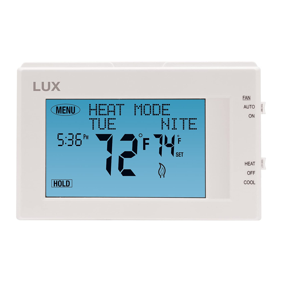
T X 960 0TSa Mode Switch Menu Button MENU AUTO ˚ ˚ HEAT Clock COOL System Mode Switch Room Temperature Set Temperature SYSTEM COMPATIBILITY: The electrical rating for this thermostat is 1.5 Amps per terminal, with a maximum total combined load of 3.0A for all terminals combined. COMPATIBLE WITH: •... -
Page 4: Features
FEATURES: • 1 or 2-Heat / 1-Cool, 7-day programming • Universal Compatibility for all system types • Each day of the week can be programmed separately • Easy to use, touchscreen menu operation • User-selectable periods per day (2 or 4) •... -
Page 5: Mounting Location
MOUNTING LOCATION: On replacement installations, mount the new thermostat in place of the old one unless the conditions listed below suggest otherwise. On new installations, please follow these general guidelines: 1. Mount the thermostat on an inside wall, about 5 ft. (1.5m) above the floor. 2. -
Page 6: Install Thermostat Base
INSTALL THERMOSTAT BASE: Mode Switches THERMOSTAT TOP VIEW 1. Strip wire insulation leaving only 3/8 in. (9.5mm) bare wire ends, and clean off any corrosion present. 2. Fill the wall opening with non-combustible insulation to prevent drafts from affecting the thermostat’s normal operation. 3. -
Page 7: Wiring Information
WIRING INFORMATION: CONNECTING THE WIRES: When attaching the wires to the thermostat, please ensure that the bare wire ends are held ALL the way into the terminal block while the screw is being tightened. WIRING BASE PLATE NOTICE: This thermostat model is part of a family of similar models that have the same general visual appearance. - Page 8 WIRING DIAGRAM NOTES: (Important, please read all notes before connecting wires) • If the information provided in the following wiring diagrams does not clearly represent or match your system, please refer to the “TECHNICAL ASSISTANCE” section of this manual, and contact us before removing any of your existing thermostat wiring.
-
Page 9: Wiring Diagrams
WIRING DIAGRAMS: DIAGRAM SYSTEM TYPE / DESCRIPTION PAGE # CONVENTIONAL: HEATING ............10 1-STAGE OR 2-STAGE 2, 3, 4, 5 WIRES CONVENTIONAL: HEATING ............11 3-WIRE ZONE VALVE 3, 4 WIRES CONVENTIONAL: COOLING ............12 1-STAGE 3, 4 WIRES CONVENTIONAL: HEATING AND COOLING ........13 1-STAGE HEAT 4, 5 WIRES CONVENTIONAL:... -
Page 18: Hardware Setup Options
HARDWARE SETUP OPTIONS: On the thermostat’s circuit board, there is a row of DIP switches, labeled #1 through #7. The position of these switches will change how the thermostat operates, and also how information is conveyed to you on the LCD display screen. - Page 19 SWITCH #4 (SCALE): [OFF/RIGHT = F, default] All temperature values are displayed using the Fahrenheit scale. [ON/LEFT = C] This setting displays all temperature values using the Celsius scale. SWITCH #5 (TIME): [OFF/RIGHT = 12 HR, default] This setting displays the clock times and temperature program period start time values on the screen using US standard AM and PM values.
-
Page 20: Complete The Install
GAS / ELEC SLIDE SWITCH (FAN OPERATION): This switch is a physical component by itself on the circuit board, and is much larger than the DIP BATTERY switches listed above. [UP = GAS, default] This setting lets the heating system control the blower fan automatically by itself. -
Page 21: Operating Instructions
NOTE: The Fan Mode switch only works if your system provides a wire for the thermostat’s “G” wire terminal, to control a blower fan. The Fan Mode switch has no effect in systems that do not have a blower fan (such as a hot water radiator system). - Page 22 PERIOD HEAT MODE COOL MODE 6:00 AM 70 °F (21 °C) 6:00 AM 78 °F (26 °C) MORN 8:00 AM 62 °F (17 °C) 8:00 AM 82 °F (28 °C) 6:00 PM 70 °F (21 °C) 6:00 PM 78 °F (26 °C) 10:00 PM 62 °F (17 °C) 10:00 PM 75 °F (24 °C) NITE...
- Page 23 LCD DISPLAY BACKLIGHT: The display screen is lighted to assist viewing at nighttime, or in locations with low light levels. A press of any area on the touch panel will light the display for approximately 10 seconds. Any screen presses that occur while the light is on will reset the 10-second timer, causing the screen to remain illuminated for an additional 10 seconds.
-
Page 24: Temperature Programs
STATIC NOTICE: This thermostat is protected against normal static electric discharges, however to minimize the risk of damaging the unit in extremely dry weather, please touch a grounded metal object before touching your thermostat. TEMPERATURE PROGRAMS: By default, this thermostat has 4 separate program periods for both Heat and Cool mode, they are: MORN, DAY, EVE, and NITE. -
Page 25: Advanced Features
and DOWN buttons, select the day that you want to copy from. Press the NEXT button one time. Your copy from day should now be on steady with the day under the word “TO” flashing. Use the UP and DOWN buttons to select the day that you would like to copy to. - Page 26 second heating stage to turn on. This setting can be used to conserve energy in situations where the second heating stage is more costly to operate when compared to the first stage. Cut-In / Cut-Out Stage) 70˚F Set Temperature Swing Setting= #2 (+/- 0.5˚F) Offset **...
-
Page 27: Temperature Calibration
TEMPERATURE CALIBRATION DESCRIPTION: The internal temperature sensor in this thermostat is accurately calibrated at the factory, and in most cases, alterations to this setting should not be needed. The Temperature Calibration feature allows you to manually offset the measured temperature by as much as plus or minus 5°F (3°C) degrees from its original value. - Page 28 NOTE: The Setback settings need to be performed in a timely manner, as the thermostat will timeout and automatically exit these adjustment screens after approximately 10 seconds without a button press. TO START A SETBACK: Press the MENU button, then press the SCROLL button until “TEMPERATURE SETBACK”...
- Page 29 The following examples are shown for setting the maximum set temperature for Heat mode. Setting the Temperature Limit Stop for Cool mode is done in the same exact manner with the System Mode switch in the Cool position, and instead you will be setting the minimum set temperature for cooling. Once a Temp Stop Lock Code has been selected, this same code is used for both Heat and Cool temp stops.
- Page 30 KEYPAD LOCKOUT: You can lock the touch-panel buttons to prevent unauthorized tampering of your thermostat settings. NOTE: These keypad lock instructions need to be performed in a timely manner, as the thermostat will timeout and automatically exit the keypad lock screens and return to the Normal Run screen after approximately 10 seconds without a button press.
- Page 31 The Air Filter Monitor counts the duration of filter usage that has occurred, since the last time the Filter Monitor has been reset. This feature is for information purposes only, and does not affect the operation of your heating or cooling equipment, or the thermostat.
-
Page 32: Hardware Reset
for viewing the Energy Usage while in Heat mode. Viewing the Cool mode information is done in the same exact manner in Cool mode. TO VIEW THE ENERGY USAGE TIMERS: Press the MENU button, then press the SCROLL button until “REVIEW HEAT ENERGY USAGE” is shown, then press the OK button. -
Page 33: Battery Replacement
COMPRESSOR PROTECTION BYPASS: This optional feature permits the installer or service technician to temporarily disable the built in compressor protection delays. This is most useful for diagnosing and testing the heating and cooling systems after installation is complete, and should not be used during normal operation. -
Page 34: Technical Assistance
TECHNICAL ASSISTANCE: If you have any problems installing or using this thermostat, please carefully and thoroughly review the instruction manual. If you require assistance, please contact our Technical Assistance department at 856-234-8803 during regular business hours between 8:00AM and 4:30PM Eastern Standard Time, Monday through Friday. - Page 35 MENU AUTO ˚ ˚ HEAT COOL Mt. Laurel, New Jersey 08054, USA http://www.luxproducts.com 856-234-8803...
Need help?
Do you have a question about the SMART TEMP TX9600TSa and is the answer not in the manual?
Questions and answers