
Related Manuals for JBL CSMA 180


Summary of Contents for JBL CSMA 180
- Page 1 CSMA Commercial Series CSMA 180 CSMA 1120 CSMA 240 CSMA 280 CSMA 2120 Commercial Series Mixer-Amplifier Operation Manual CSMA Mixer-Amplifiers...
-
Page 2: Table Of Contents
The information provided in this manual was deemed accurate as of the publication date. However, updates to this information may have occured. Trademark Notice: JBL is registered trademark of JBL International. Other trademarks are the property of their respective owners. -
Page 3: Important Safety Instructions
IMPORTANT SAFETY INFORMATION WARNING FOR YOUR PROTECTION READ THE FOLLOWING: KEEP THESE INSTRUCTIONS HEED ALL WARNINGS FOLLOW ALL INSTRUCTIONS THE APPARATUS SHALL NOT BE EXPOSED TO DRIPPING OR SPLASHING LIQUID AND NO OBJECT FILLED WITH LIQUID, SUCH AS VASES, SHALL BE PLACED ON THE APPARATUS The symbols shown above are internationally accepted symbols that warn of potential hazards with electrical products. - Page 4 IMPORTANT SAFETY INFORMATION U.K. MAINS PLUG WARNING If you want to dispose this product, do not mix it with gen- eral household waste. There is a separate collection system for used electronic products in accordance with legislation A molded mains plug that has been cut off from the cord is that requires proper treatment, recovery and recycling.
-
Page 5: Jbl Declaration Of Conformity
Equipment Type: Commercial Audio Mixer-Amplifiers Model names: CSMA 180, CSMA 1120, CSMA 240, CSMA 280, CSMA 2120 We, Harman International, declare under our sole responsibility that the product, to which this declaration relates, is in conformity with the following standards. -
Page 7: Welcome
70V or 100V outputs. The product includes a rack mounting kit for installations to a cabinet. The system can be easily expanded with additional JBL Commercial Series Amplifiers and Com- mercial Series Mixers. Provisions are included for a remote volume control using the JBL CSR-V control module. -
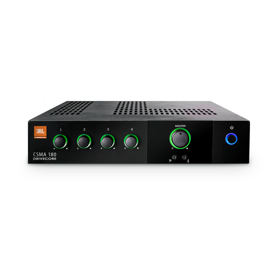
Page 8: Front Control Panels And Indicators
1.2 Front Panel Controls and Indicators Figure 1.2 Front View A. Input Level Controls B. Input signal presence is indicated by green illumination of the ring around the input level controls C. Output Volume Controls D. Illuminated ring around the output volume control will light green with signal presence while red indicates clipping, i.e. -
Page 9: Rear Panel Controls And Connectors - Four Channel
Phantom Power Switch – Applies 27V phantom power source for microphones. Remote volume connector – RJ-45 style connector to connect to JBL CSR-V control module G. Mic/Line Selection Switch – Allows the user to select the gain depending upon the source used H. -
Page 10: Rear Panel Controls And Connectors - Eight Channel
Amplifier Output Connector – Outputs available for low impedance or constant voltage systems. C. Remote Volume Control – RJ45 style connector to connect to a JBL CSR-V control module. D. Dip switches for input routing, phantom power, and 70/100V operation... - Page 11 LINE LINE LINE MONO SUM MONO SUM MONO SUM PRIORITY CH 1 VOX LINE LINE LINE CH 5 VOX PRIORITY MONO SUM MONO SUM MONO SUM Mic/Line Input Connector – 3 pin Euro-block connector for a balanced input source. (Ch 2-4 & 6-8) G.
-
Page 12: Important Safety Instructions
2.0 Setup 2.1 Unpacking Your Amplifier Please unpack and inspect your amplifier for any damage that may have occurred during transit. If damage is found, notify the transportation company immediately. Only you can initiate a claim for shipping damage. We will be happy to help as needed. - Page 13 Figure 2.2.1 Dimensions CSMA 180, CSMA 1120 218.44 mm [8.6 in] 303.4 mm [11.9 in] CSMA 240, CSMA 280, CSMA 2120 436.88 mm [17.2 in] 303.4 mm [11.9 in] Figure 2.2.2 Mounting Kit long angle bracket (CSMA180/CSMA1120 only) flat bracket...
- Page 14 Figure 2.2.3 Rack mounting of two half rack Mixer units. Solution A: Rack Mounting Two Half Rack Mixer Amplifiers To install two half-rack width units in your cabinet system, refer to Figure 2.2.3 and follow the steps below: Align two modules side by side and upside down with the front panel towards the same direction.
- Page 15 Figure 2.2.4 Rack Mounting a Half Rack Mixer Amplifier Solution B: Rack Mounting Single Half Rack Mixer Amplifier To install a single half-rack unit, refer to Figure 2.2.4 and follow the steps below: Determine which side of the rack opening will be used for the amplifier and attach the long angle bracket to the other side at the front of the amplifier using the screws provided.
- Page 16 Figure 2.2.5 Rack Mounting Full Rack Mixer Amplifier Solution C: Rack Mounting Full Rack Mixer Amplifier To install a full-rack width unit, refer to Figure 2.2.5 and follow the steps below: Attach the front angle brackets to each side of the front of the amplifier using the screws provided.
-
Page 17: Ensuring Proper Cooling
2.3 Ensuring Proper Cooling When using an equipment rack, keep a minimum space of 4 inches (10cm) from the top surface of the unit. Close any open spaces in the rack with blank panels. DO NOT block any air vents. The side walls of the rack should be a minimum of 2 inches (5 cm) from the amplifier sides. -
Page 18: Output Wiring And Connectors
To drive distributed speaker systems designed to operate at 70V or 100V, connect to the corresponding output terminals. JBL recommends using pre-built or professionally wired, high-quality, two-conductor, heavy gauge speaker wire. Speakers wires should be twisted cable, if possible. To prevent the possibility of short-circuits, the wires should be stripped back no greater than 6 mm (1/4 inch), see Figure 2.5.2. -
Page 19: Wiring Your Audio System
Figure 2.6 Wiring Audio System Professional audio system 100-240 V~ 50/60Hz AMP OUT CLASS 2 MONO SUM LINE LINE Hi-Z PHANTOM WIRING PRIORITY CSR-V ONLY 100V 70.7V COM LINE LINE CAUTION - TO REDUCE THE RISK OF ELECTRIC SHOCK, GROUNDING OF THE CENTER PIN OF THE PLUG CH2-4 IN / AUX OUT MUST BE MAINTAINED. -
Page 20: Connecting To Ac Mains
2.7 Connecting to AC Mains Connect your amplifier to the AC mains power source (power outlet) with the supplied AC power cord. First, connect the IEC end of the cord set to the IEC connector on the amplifier; then, plug the other end of the cord set to the AC mains. When properly connected to a live power source, the power ring should illuminate with a green color. -
Page 21: Operation
10. If the line voltage to the amplifier is too low, the low voltage protection function will be activated. The power light ring will change from blue to green. CAUTION: JBL is not liable for damage that results from overdriving other system components. -
Page 22: Input Routing
3.2 Input Routing The two channel models, CSMA240, CSMA280 INPUT ROUTING and CSMA2120 include a default routing of input channels 1-4 to amplifier 1 and input channels 5-8 1 - CH1 TO AMP2 2 - CH2 TO AMP2 to amplifier 2. The user may also take any input 3 - CH3 TO AMP2 4 - CH4 TO AMP2 and have it routed to both outputs by selecting the... -
Page 23: Priority Muting
3.6 Priority Muting With CSMA180 and CSMA1120 Input Channel 1 may be used as a priority channel, muting all other channels when pins 4 and 5 are shorted using a switch closure. If the amplifier has entered sleep mode due to inactivity, invoking priority will also bring the unit out of sleep and ready for transmitting an announcement. -
Page 24: Troubleshooting
4.0 Troubleshooting CONDITION: No power to the mixer-amplifier so that the power ring is not illuminated. POSSIBLE REASON: The mixer-amplifier is not plugged into the power receptacle CONDITION: No sound or low sound. POSSIBLE REASON: The input signal is not present or at a very low level. POSSIBLE REASON: The Master Volume control is turned down. -
Page 25: Appendix A: Target Performance Specifications
Appendix A: Target Performance Specifications Performance CSMA 180 CSMA 1120 CSMA 240 CSMA 280 CSMA 2120 Max Output Power per Channel into 120W 120W 4 Ω or 8 Ω; 1kHz, ≤ 0.5% THD Insertion Loss (70V & 100V outputs) 1 dB maximum... -
Page 26: Appendix B: Block Diagram
Appendix B : Block Diagram Figure C CSMA 2120/280/240 Block Diagram Phantom Power (SW6) Input Gain Line Mic/Line [Bal] CH1 TO AMP1 Gain 1 ∑ CH1 TO AMP2 CH1 VOX CH1 Priority CH1 PTT Input Gain Line CH2 TO AMP1 ∑... - Page 27 Preamp Line Out 1 Preamp Line Out 1 SPI 1 Clip 1 SPI 1 Clip 1 ∑ ∑ Tone Control Tone Control Bass Treble Bass Treble Master 1 Master 1 Scaling VCA 1 Scaling VCA 1 HPF CNTL (SW5) HPF CNTL (SW5) Limiter Limiter...
-
Page 28: Appendix C: Contact Information
For additional information, please consult JBL Professional Customer Service, your system installer or retailer. On The World Wide Web: www.jblcommercialproducts.com Professional Contacts, Outside the USA: Contact the JBL Professional Distributor in your area. A complete list of JBL Professional international distributors is provided at our U.S.A. Website: www.jblpro.com... - Page 32 JBL Commercial 8760 South Sandy Pkwy. Sandy, UT 84070 USA (801) 566-8800 Part Number: 5025072 Issue: 07/13...
Need help?
Do you have a question about the CSMA 180 and is the answer not in the manual?
Questions and answers