Table of Contents
Advertisement
Advertisement
Table of Contents

Related Manuals for Respironics BiPAP autoSV Advanced


Summary of Contents for Respironics BiPAP autoSV Advanced
-
Page 1: User Manual
with SmartCard User Manual... - Page 2 © 2009 Koninklij ke Philips Electronics N.V. and its affi liates. All rights reserved.
-
Page 3: Table Of Contents
. Definitions .......................... . What is Bi-level Ventilation? .................... . What is the Device? ........................ . Symbols ............................ . How to Contact Respironics .................... Chapter : Device Controls and Display Features ................ . Pressure On/Off Button ...................... . Control Panel ............................ - Page 4 Chapter : Alarms .......................... . Introduction to Alarms ...................... . What to Do When an Alarm Occurs .................. . Alarm Tables .......................... .. High Priority Alarms .................... .. Medium Priority Alarms .................... .. Low Priority Alarms ..................... Chapter : Troubleshooting ....................... Chapter : Cleaning and Maintenance ........................
- Page 5 1: P HAPTER ACKAGE ONTENTS Your device should include the following items. If any of these items are missing, contact your health care professional. Carrying Case BiPAP autoSV Advanced ™ with SmartCard Disposable Ultra-fine Filter Reusable Gray Foam Filters User Manual Filter Cap Power Cord Flexible Tubing...
-
Page 6: Chapter : Warnings And Cautions
If oxygen is used with the device, the oxygen fl ow must be turned off when the device is not in use. • If you are using oxygen, the device must be equipped with the Respironics Pressure Valve (Part number 302418). Failure to use the Pressure Valve could result in a fi re hazard. - Page 7 • Repairs and adjustments must be performed by Respironics - authorized service personnel only. Unauthorized service could cause injury, invalidate the warranty, or result in costly damage. •...
-
Page 8: Intended Use
Central Sleep Apnea or Cheyne-Stokes Respiration (CSR). Th e device may be used in the hospital or home. Th e device is intended for use with nasal masks and full-face masks as recommended by Respironics. Th e device is to be used only on the instruction of a trained health care professional. - Page 9 3: I HAPTER NTRODUCTION TO THE EVICE 3.1 D EFINITIONS Th e following terms appear throughout this manual: Apnea A condition marked by the cessation of spontaneous breathing. Breaths Per Minute CPAP Continuous Positive Airway Pressure EPAP Expiratory Positive Airway Pressure Exhaled Tidal Volume (V Th e exhaled volume of each breath High Priority Alarm...
-
Page 10: What Is Bi-Level Ventilation
3.2 W HAT IS LEVEL ENTILATION Bi-level ventilation with the device helps you to breathe by supplying two levels of air pressure. Th e device provides a higher pressure—known as IPAP (Inspiratory Positive Airway Pressure)—when you inhale, and a lower pressure—known as EPAP (Expiratory Positive Airway Pressure)—when you exhale. Th e higher pressure makes it easier for you to inhale, and the lower pressure makes it easier for you to exhale. - Page 11 A breathing circuit, shown in Figure 3–3, consists of: • Circuit tubing to deliver air from the device to your interface (e.g., mask) • A mask or other patient interface device to deliver the prescribed pressure to your nose or nose and mouth, depending on which interface has been prescribed for you •...
-
Page 12: Symbols
ONTACT ESPIRONICS To have your device serviced, contact your health care professional. If you need to contact Respironics directly, call the Respironics Customer Service department at 1-724-387-4000 or +49 8152 93060. You can also use one of the following addresses:... -
Page 13: Pressure On/Off Button
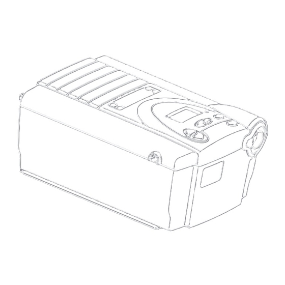
4: D HAPTER EVICE ONTROLS AND ISPLAY EATURES Figure 4–1 shows the location of the device’s alarm power indicators, control panel, Pressure On/Off button, and the breathing circuit connection. Alarm and Power Indicators Control Panel Breathing Circuit Connection Pressure On/Off Button Figure 4–1 Device Front and Top 4.1 P RESSURE... - Page 14 4.2 C ONTROL ANEL Th e control panel contains the following control buttons and indicators. 4.2.1 C ONTROL UTTONS Th e control buttons on the control panel are shown in Figure 4–3. Scroll Button RESET RESET Alarm RESET RESET Reset HEAT Button RAMP...
-
Page 15: Alarm And Power Indicators
4.2.2 A LARM AND OWER NDICATORS Figure 4–4 shows the device’s alarm and power indicators. High Priority AC Power Alarm LED (Red) Indicator (Green) DC Power Low/Medium Priority Indicator (Green) Alarm LED (Yellow) Figure 4–4 Alarm and Power Indicators Th e green AC Power LED lights up when the device is connected to AC Power. - Page 16 Th e information shown on the display screen is defi ned as follows: Indicates that the device requires user attention as indicated on the screen. Indicates that an apnea alarm has occurred. Indicates that a breath rate setting is being displayed. Th is symbol fl ashes when the device is providing timed backup breaths.
-
Page 17: Breathing Circuit Connection
Respironics Isolation cable (Part Number 1012865). Th e rear panel contains the following: Communications Th is connector accepts the Respironics Communications cable for computer Connector and external communications or a remote alarm. (Use only with an IEC 60950 approved computer.) -
Page 18: Installing The Air Filters
5: S HAPTER ETTING UP THE EVICE 5.1 I NSTALLING THE ILTERS Th e device uses one or two removable fi lters at the air inlet. Th e disposable white ultra-fi ne fi lter is optional. You must install the gray foam fi lter before operating the device. Th e foam fi lter is washable and reusable. CAUTION: A properly installed, undamaged foam fi... - Page 19 5.3 C ONNECTING THE REATHING IRCUIT To connect your breathing circuit to the device, complete the following steps: Connect one end of the circuit tubing to the outlet of the bacteria fi lter (if using one) and connect the inlet of the bacteria fi lter to the large connector on the device as shown in Figure 5–2. If you are not using a bacteria fi...
- Page 20 If you are using a mask with a separate exhalation device, connect the open end of the circuit tubing to the exhalation device as shown in Figure 5–4. Position the exhalation device so that the vented air is blowing away from your face. Circuit Tubing Exhalation Port Figure 5–4 Connecting a Exhalation Device...
-
Page 21: Complete Setup
5.4 C OMPLETE ETUP Figure 5–6 shows the completed breathing circuit setup. Patient Interface Exhalation Port Circuit Tubing Bacteria Breathing Filter Circuit (Optional) Connection Figure 5–6 Complete Breathing Circuit 5.5 P LUGGING THE EVICE You can use AC or DC power to operate the device. WARNING: Th e DC power option is not intended as a battery backup when using AC power. -
Page 22: Using Dc Power
DC P SING OWER You can operate the device on DC power by using the Respironics DC power adapter accessory. See the DC power adapter instructions for more information. CAUTION: Use only the Respironics DC power adapter available from your health care professional. - Page 23 6: O HAPTER PERATING THE EVICE 6.1 S TARTING THE EVICE Plug in the device to an AC or DC power source to power up the device. A confi rmation alarm sounds, and the control pad buttons light up. NOTE: If the alarm does not sound or the buttons do not light up, the device requires servicing.
- Page 24 NOTE: With the exception of the button, the control pad is inactive during these fi rst three screens. Each of these screens appears for approximately 1-3 seconds. d. Th e next screen that appears is the Standby screen, shown in Figure 6–4. Th is indicates that the device is in the Standby state (the blower is off...
-
Page 25: Changing The Humidifier Setting
6.2 C HANGING THE EVICE ETTINGS You can view the following settings and indicators on the display screen: • Measured pressure • Backlight settings • Humidifi er, SmartCard and Ramp status • Patient alarms • Measured parameters (Leak, Respiratory Rate, Minute Ventilation, Exhaled Tidal Volume) Additionally, you can view and modify the following settings using the display screens: •... -
Page 26: Navigating The User Display Screens
You can exit this screen by pressing the Left or Right User buttons or the button. For additional SILENCE SILENCE information on using a humidifi er with the device, see Chapter 10. To turn the humidifi er ON/OFF, press the button until the device beeps twice and the HEAT symbol appears/disappears. -
Page 27: Changing The Flex Setting
6.2.2.1 C HANGING THE ETTING Th e Flex screen is displayed only if it is prescribed. If the Flex feature is enabled, you can adjust the Flex setting to fi nd the setting that provides you with the most comfort. If the screen shown in Figure 6–8 does not display, you cannot adjust this setting. -
Page 28: Changing The Ramp Starting Pressure
6.2.2.3 C HANGING THE TARTING RESSURE Th e device is equipped with an optional ramp feature. Th is feature will reduce the pressure and then gradually increase (ramp) the pressure to the prescription pressure setting so you can fall asleep more comfortably. - Page 29 6.3 M ONITORING EASURED ARAMETERS You can view four measured parameters—leak, respiratory rate, minute ventilation, and exhaled tidal volume. To access these screens from the Monitoring or Standby screens, press the small circular Scroll RESET button ( ) located near the RESET button.
- Page 30 Respiratory Rate Screen Th is screen, shown in Figure 6–14, shows the average rate of respiration for the previous six breaths. Th e display is updated at the end of each breath. Figure 6–14 Respiratory Rate Screen Minute Ventilation Screen Th is screen, shown in Figure 6–15, shows the estimated Exhaled Minute Ventilation (the volume of air received on a per minute basis) based on the average of the previous six breaths.
- Page 31 7: A HAPTER LARMS 7.1 I NTRODUCTION TO LARMS Th e device provides three alarm levels: high, medium, and low priority. High Priority Th ese alarms require immediate response. Th e alarm signal consists of a red LED indicator and a sound that is either a periodic pattern consisting of a two-second beep followed by two seconds of silence or a pattern of three beeps, a pause, and then two more beeps.
- Page 32 7.2 W HAT TO HEN AN LARM CCURS Th e following example applies to most alarm conditions. Follow these steps unless otherwise directed by the alarm tables that follow. Look at the alarm indicators and listen to the alarm sound. Alarm LED Lights Up Figure 7–3 Alarm LED Lights Up...
- Page 33 7.3 A LARM ABLES Th e following tables summarize the high priority, medium priority, and low priority alarms. 7.3.1 H RIORITY LARMS Alarm Alarm Display Device Possible Your Message Cause Sound Action Action Press the • • • • • Breathing circuit is RESET RESET...
- Page 34 7.3.2 M EDIUM RIORITY LARMS Your Alarm Alarm Display Device Possible Action Message Sound Action Cause • • • Operates Battery is nearly Yellow Flash Press the RESET RESET discharged. button to reset the DC Power alarm. Replace the LED Flashes battery.
- Page 35 8: T HAPTER ROUBLESHOOTING Th is chapter describes problems that you may experience with your device or mask and provides possible solutions. Problem Why It Happened What To Do Th e device does not If the power LED is off , there’s Check the outlet power and verify that operate when you no power at the outlet or the...
- Page 36 Contact your health care professional or performance of or water has been spilled onto Respironics for directions on how to have the device. or into the device or the power your device serviced. Please have the serial supply.
- Page 37 fi rst. If the error message appears again, contact your health care professional or Respironics for directions on having your device serviced. Please have your serial number ready when you call.
- Page 38 9: C HAPTER LEANING AND AINTENANCE 9.1 C LEANING THE EVICE Before cleaning or performing any routine maintenance, always make sure the device is not operating and disconnect the device from the power source. NOTE: Th e following cleaning instructions are for the device only. To clean the accessories, refer to each accessory’s instruction sheet.
- Page 39 If needed, wash the gray foam fi lter in warm water with a mild detergent. Rinse thoroughly to remove all detergent residue. Allow the fi lter to dry completely before reinstalling it. If the foam fi lter is torn, replace it. (Only Respironics-supplied fi lters should be used as replacement fi lters.) CAUTION: Never install a wet fi...
- Page 40 Oxygen may be added to the mask connection. Please note the warnings listed below when using oxygen with the device. WARNING: If you are using oxygen, your device must be equipped with the Respironics Pressure Valve (Part number 302418). Failure to use the Pressure Valve could result in a fi re hazard. WARNING: Oxygen accelerates fi...
- Page 41 11: S HAPTER PECIFICATIONS NVIRONMENTAL Operating Storage Temperature 5ºC to 35ºC -20ºC to 60ºC 15 to 95% 15 to 95% Relative Humidity (non-condensing) (non-condensing) Atmospheric Pressure 83 to 102kPa (5600 feet to sea level) HYSICAL Dimensions: 24.8 cm L x 16.8 cm W x 11.2 cm H (9.75 in.
- Page 42 ± (1 + 0.15 of reading) L/min Ventilation Leak Rate ± (5 + 0.15 of reading) L/min WEEE/R HS R ECYCLING IRECTIVES If you are subject to the WEEE/RoHS recycling directives, refer to www.respironics.com for the passport for recycling this product. User Manual...
- Page 43 A: EMC I PPENDIX NFORMATION ’ Th is device is intended for use in the UIDANCE AND ANUFACTURER ECLARATION LECTROMAGNETIC MISSIONS electromagnetic environment specifi ed below. Th e user of this device should make sure it is used in such an environment. MISSIONS OMPLIANCE LECTROMAGNETIC...
- Page 44 ’ Th is device is intended for use in the UIDANCE AND ANUFACTURER ECLARATION LECTROMAGNETIC MMUNITY electromagnetic environment specifi ed below. Th e user of this device should make sure it is used in such an environment. IEC 60601 T MMUNITY EVEL OMPLIANCE...
- Page 45 OTES User Manual...
- Page 46 OTES User Manual...
- Page 47 (2) years from the date of sale by Respironics, Inc. to the dealer. If the product fails to perform in accordance with the product specifi...
- Page 48 REF 1058267 1056937 JB 11/25/2008...
Need help?
Do you have a question about the BiPAP autoSV Advanced and is the answer not in the manual?
Questions and answers
How to set humidifier
To set the humidifier on a Respironics BiPAP autoSV Advanced:
1. From the Standby or Monitoring screen, press and hold the button for several seconds until the Humidifier Setting screen appears.
2. Press the button to increase the setting or press the RAMP button to decrease it. The settings range from 1 to 5.
3. The setting changes immediately as you adjust it.
4. After reaching the maximum (5), pressing the increase button again will roll the setting back to 1, and vice versa.
This answer is automatically generated