Table of Contents
Advertisement
Advertisement
Table of Contents

Related Manuals for Hiprom Technologies 1756HP-GPS

Summary of Contents for Hiprom Technologies 1756HP-GPS
-
Page 1: User Manual
1756 -GPS USER MANUAL Rev 2.8 – March 2009... -
Page 2: Table Of Contents
1756HP-GPS - User Manual Rev 2.8 Table of Contents Chapter 1 Introduction ......................3 Chapter 2 Module Accessories ..................4 Chapter 3 Module Operation.....................5 Chapter 4 Installing the Module ..................7 Chapter 5 Configuring the Module..................8 Chapter 6 I/O Address Map ....................12 Chapter 7 Module Specific Commands ................17... -
Page 3: Chapter 1 Introduction
1756HP-GPS - User Manual Rev 2.8 INTRODUCTION CHAPTER 1 The 1756HP-GPS module provides accurate time and position information and services for the Allen-Bradley ControlLogix PLC system. The module makes use of Global Positioning System (GPS) technology to derive accurate time which is synchronized with the atomic clocks located on the GPS satellites. -
Page 4: Chapter 2 Module Accessories
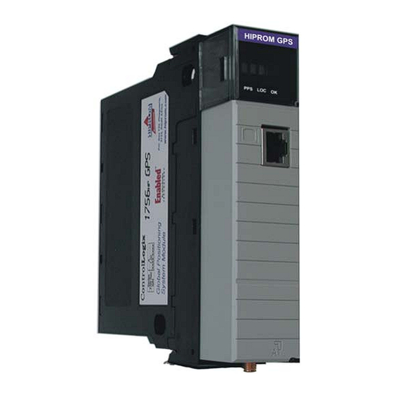
• 5m RG58 patch lead with a SMA male and TNC male connector on either end • 3.3V active 50Ω hard mount antenna • 1756HP-GPS user manual HIPROM GPS LO CK Figure 2.1 : 1756HP-GPS module with antenna and patch-lead Page 4 of 39... -
Page 5: Chapter 3 Module Operation
1756HP-GPS - User Manual Rev 2.8 MODULE OPERATION CHAPTER 3 The 1756HP-GPS module is designed to operate within the Allen-Bradley ControlLogix PLC system. All power required for the module’s operation is derived from the 1756 backplane. Alphanumeric Display Status LEDs... - Page 6 8 GPS receiver channels : • Satellite Identifier (PRN) • Current Satellite Azimuth • Current Satellite Elevation • Signal Strength The 1756HP-GPS module supports two unconnected time conversion services, namely: • CST UTC and Gregorian • UTC Gregorian This allows the user by means of a custom message service to convert between different time formats.
-
Page 7: Chapter 4 Installing The Module
1756HP-GPS - User Manual Rev 2.8 INSTALLING THE MODULE CHAPTER 4 GPS utilizes a spread spectrum signal in the 1.5GHz range, and thus cannot penetrate conductive or opaque surfaces. Thus the antenna should be mounted in a horizontal position with an unobstructed view of the sky. -
Page 8: Chapter 5 Configuring The Module
CONFIGURING THE MODULE CHAPTER 5 A direct connection between the controller and the 1756HP-GPS module is required to transfer I/O data to and from the module. In addition the module supports various unconnected messages that can be used to retrieve particular information. - Page 9 1756HP-GPS - User Manual Rev 2.8 Figure 5.2 : Select Generic 1756 Module ( 1756-MODULE ) Figure 5.3 : Configure module’s parameters Page 9 of 39...
- Page 10 RSLogix. To ensure that ControlLogix PLC’s running different versions can be time synced using the 1756HP-GPS module the user must select if v16 is used or not. The last bit (least significant bit) of the second byte of the configuration image configures the module to use or not use v16 UTC time.
- Page 11 5.2. Coordinate System Time Master It is important that at least one controller or 1756HP-GPS module in the ControlLogix rack be configured as the Coordinate System Time master. This can be configured in RSLogix5000 by right-clicking on the Controller and selecting Properties. Ensure that the checkbox as indicated below is checked to make the controller the CST master;...
-
Page 12: Chapter 6 I/O Address Map
I/O ADDRESS MAP CHAPTER 6 The input and output image of the 1756HP-GPS module is defined in the following sections. Appendix A and B provide example code and recommended structures that can be used to extract and view the data. - Page 13 1756HP-GPS - User Manual Rev 2.8 6.2. Input Image Description Field/Value Description Location Type Module Status Module OK 0 = Module has faulted Local:s:I.Data[0].16 1 = Module is operating properly Satellite Lock GPS Locked 0 = Not tracking sufficient satellites to provide Local:s:I.Data[0].17...
- Page 14 1756HP-GPS - User Manual Rev 2.8 A duplicate CST master has been detected Dup Master 0 = No duplicate CST master detected Local:s:I.Data[0].28 1 = A duplicate CST master is detected This module is the local rack CST master CST Master 0 = This module is not the CST master Local:s:I.Data[0].29...
- Page 15 1756HP-GPS - User Manual Rev 2.8 Distance from Earth-centre along the X - axis. (metres) Position is calculated with respect to the WGS-84 ECEF Earth-Centred Earth-Fixed co-ordinate system. Local:s:I.Data[23] REAL Position X The X-axis is defined as the vector with origin at the earth's centre and passing through the intersection of the equator and Greenwich meridian.
- Page 16 1756HP-GPS - User Manual Rev 2.8 6.3. Output Image 6.4. Output Image Description Field Description Location Type Local:s:O.Data[0] Reserved Reserved 64Bits 64BIT Local:s:O.Data[1] Time Zone Configuration Used to set the module to report in local time standard. Time zone REAL Local:s:O.Data[2]...
-
Page 17: Module Specific Commands
MODULE SPECIFIC COMMANDS CHAPTER 7 The 1756HP-GPS module offers specific commands that enable the system to retrieve GPS satellite information, as well as performing time base conversions. These are accomplished using unconnected messaging via the MSG ladder instruction. This enables communication to the module without a direct connection. - Page 18 1756HP-GPS - User Manual Rev 2.8 The message instruction will return the information in the following structure : Field Bytes Type Description Satellite[n] Prn SINT Satellite number [1..32] Satellite[n] Ele SINT Elevation [0..90] Satellite[n] Azm Azimuth [0..360] Satellite[n] SnR DINT Signal –...
- Page 19 7.2. Converting Time Bases The 1756HP-GPS stores a rolling log of the CST/UTC pairs for the last 1 hour. Timestamps in a system can either be CST or UTC values. The 1756HP-GPS module provides functionality for converting between values that are within the last hour.
- Page 20 1756HP-GPS - User Manual Rev 2.8 The structure of the request is as follows : Field Bytes Type Description DINT[2] CST value Table 7.4 : CST->UTC conversion request data. A successful conversion will result in the following response : Field...
- Page 21 1756HP-GPS - User Manual Rev 2.8 7.4. Converting UTC to Gregorian Time By supplying the full 64 bit UTC value, the module will return the corresponding full Gregorian date. Configuration of this message is illustrated below. Figure 7.3: Configuring the MSG UTC->Gregorian conversion request instruction.
- Page 22 1756HP-GPS - User Manual Rev 2.8 The structure of the request is as follows: Field Bytes Type Description DINT[2] UTC value Table 7.7 : UTC->Gregorian conversion response data. A successful conversion will result in the following response : Field Bytes...
-
Page 23: Chapter 8 Module Status
1756HP-GPS - User Manual Rev 2.8 MODULE STATUS CHAPTER 8 The following sections describe the various status of the module and how they may be determined via the 3 bi-color (Green / Red) LED’s and the message on the display. -
Page 24: Status Display
1756HP-GPS - User Manual Rev 2.8 8.2. Status Display Init Initialization of Module The module is initialized only on power-up. Firmware Revision The firmware revision number is displayed on power-up. AntO Antenna Open Circuit Indicates the Antenna is not connected or damaged. - Page 25 1756HP-GPS - User Manual Rev 2.8 Tracking only 1 Satellite Trk2 Tracking only 2 Satellites Trk3 Tracking only 3 Satellites SBad Current Satellite is Bad The satellite signal currently being acquired is suspect or unusable. Satellite data request Module is processing a satellite data request C->U...
-
Page 26: Appendix Aplc Ladder Example
1756HP-GPS - User Manual Rev 2.8 PLC LADDER EXAMPLE APPENDIX A Page 26 of 39... -
Page 27: Appendix B Recommended Plc Data Types
Hiprom website. ( www.hiprom.com B.1 Input Image Structures Data of the 1756HP-GPS can be presented clearly by copying the input image to the GPSImage user-defined data type (UDT) structure. This structure utilizes the following embedded UDT structures (detailed below) •... - Page 28 1756HP-GPS - User Manual Rev 2.8 CSTOffset DINT[2] Decimal Latitude GPSPolar Degrees Decimal Minutes Decimal Seconds REAL Float Longitude GPSPolar Degrees Decimal Minutes Decimal Seconds REAL Float Altitude REAL Float Velocity GPSENU Northerly REAL Float Easterly REAL Float Upward REAL...
- Page 29 1756HP-GPS - User Manual Rev 2.8 GPSCartesian Name Data Type Style REAL Float REAL Float REAL Float Table B.4 : GPSCartesian UDT B.2 Unconnected message Structures An array of the following structure can be used to receive the satellite data requested from the module via the unconnected message.
- Page 30 1756HP-GPS - User Manual Rev 2.8 The following structure can be used for the UTC to Gregorian conversion via the unconnected message. The structure holds both the data sent and received. GPSConvUTC Name Data Type Style UTCRequest DINT[2] Decimal Year...
-
Page 31: Appendix C Specifications
1756HP-GPS - User Manual Rev 2.8 SPECIFICATIONS APPENDIX C Parameter Specification General Module Location Any Slot Electrical Backplane Current 515mA @ 5.1V 3mA @ 24V Schedules Connection Paramters 1.0ms to 750ms GPS Receiver Specification General L1 frequency (1575.42 MHz), C/A code (Standard... -
Page 32: Appendix Dgps Operation
The GPS control segment updates the system almanac weekly and the ephemeris hourly through three ground-based control stations. During normal operation, the 1756HP-GPS receiver module updates its ephemeris and almanac as needed. The performance of a GPS receiver at power-on is determined largely by the availability and accuracy of the satellite ephemeris data and the availability of a GPS system almanac. - Page 33 The cold-start search algorithm applies to a 1756HP-GPS receiver which has no memory of its previous session (i.e., is powered on without the memory backup circuit connected to a source of DC power). This is the “out of the box”...
- Page 34 SNR Mask 4.4.2 Although the 1756HP-GPS receiver is capable of tracking signals with SNRs as low as 0, the default SNR mask is set to 3 to eliminate poor quality signals from the fix computation and minimize constellation switching. Low SNR values may result from: •...
- Page 35 GPS “clocks” to correct its internal clock, which is not as stable or accurate as the GPS atomic clocks. GPS receivers like the 1756HP-GPS’s receiver output a highly accurate timing pulse (PPS) generated by its internal clock, which is constantly corrected using the GPS clocks.
-
Page 36: Appendix E Time Standards
TIME STANDARDS APPENDIX E There are many different time standards used in the world today. This chapter describes the different formats and standards used in the 1756HP-GPS module and how the relate to one another. E.1 GPS Time By synchronizing with the atomic clocks on GPS satellites the 1756HP-GPS module is able to compute accurate GPS time. - Page 37 CST by adding an offset known as the CST Offset. WCT = CST + (CST Offset) The 1756HP-GPS module calculates the required CST Offset in order to set the WCT to UTC time or local time depending on the configured Time Zone.
-
Page 38: Appendix F Glossary
1756HP-GPS - User Manual Rev 2.8 GLOSSARY APPENDIX F Communications format Format that defines the type of information transferred between an I/O module and its owner controller. This format also defines the tags created for each /O module Coordinated System Time (CST) Timer value which is kept synchronized for all modules within a single ControlBus chassis. - Page 39 1756HP-GPS - User Manual Rev 2.8 Each GPS satellite generates its own distinctive PRN code, which is modulated onto each carrier. The PRN code serves as identification of the satellite, as a timing signal, and as a subcarrier for the navigation data.
Need help?
Do you have a question about the 1756HP-GPS and is the answer not in the manual?
Questions and answers