Weslo Cadence M5 Treadmill User Manual
Uk manual
Hide thumbs
Also See for Cadence M5 Treadmill:
- Gebruiksaanwijzing (23 pages) ,
- Bedienungsanleitung (23 pages) ,
- Manuel de l'utilisateur (23 pages)
Advertisement
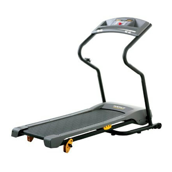
Model No. WETL12706.0
Serial No.
Serial Number
Decal
QUESTIONS?
As a manufacturer, we are com-
mitted to providing complete
customer satisfaction. If you
have questions, or if there are
missing or damaged parts,
please call:
08457 089 009
or write:
ICON Health & Fitness, Ltd.
Customer Service Department
Unit 4
Revie Road Industrial Estate
Revie Road
Beeston
Leeds, LS118JG
UK
email: csuk@iconeurope.com
CAUTION
Read all precautions and instruc-
tions in this manual before using
this equipment. Save this manual
for future reference.
USER'S MANUAL
Advertisement

Related Manuals for Weslo Cadence M5 Treadmill


Summary of Contents for Weslo Cadence M5 Treadmill
- Page 1 Model No. WETL12706.0 USER'S MANUAL Serial No. Serial Number Decal QUESTIONS? As a manufacturer, we are com- mitted to providing complete customer satisfaction. If you have questions, or if there are missing or damaged parts, please call: 08457 089 009 or write: ICON Health &...
-
Page 2: Table Of Contents
ORDERING REPLACEMENT PARTS ..........Back Cover Note: A PART IDENTIFICATION CHART, an EXPLODED DRAWING, and a PART LIST are attached in the center of this manual. WESLO is a registered trademark of ICON IP, Inc. -
Page 3: Important Precautions
IMPORTANT PRECAUTIONS WARNING: To reduce the risk of burns, fire, electric shock, or injury to persons, read the following important precautions and information before operating the treadmill. 1. It is the responsibility of the owner to ensure 11. If an extension cord is needed, use only a 3- that all users of this treadmill are adequately conductor, 1mm (14-gauge) cord that is no... - Page 4 21. Do not change the incline of the treadmill by tenance and adjustment procedures de- placing objects under the treadmill. scribed in this manual. Never remove the motor hood unless instructed to do so by an 22. Inspect and properly tighten all parts of the authorized service representative.
-
Page 5: Before You Begin
® CADENCE ing this manual, please see the front cover of this man- M5 treadmill. The CADENCE M5 treadmill combines ual. To help us assist you, please note the product advanced technology with innovative design to make model number and serial number before contacting us. -
Page 6: Assembly
ASSEMBLY Assembly requires two persons. Set the treadmill in a cleared area and remove all packing materials; do not dispose of the packing materials until assembly is completed. Note: The underside of the treadmill walking belt is coated with high-performance lubricant. During shipping, a small amount of lubricant may be transferred to the top of the walking belt or the shipping carton. - Page 7 3. Have a second person lift and hold the front end of the Frame (51). Hold a Frame Spacer (11) be- tween the Right Handrail (54) and the Frame. Attach the Right Handrail to the Frame with a Frame Pivot Bolt (1), a Frame Washer (14), and a Handrail Star Washer (9).
- Page 8 6. Attach the Console Back (93) to the Console Assembly (91) with four Console Back Screws (4). Note that there is a slot in the side of the Console Back for the Wire Harness (98). Make sure that no wires are pinched. 7.
- Page 9 8. Attach the Latch Assembly (48) to the Left Handrail (53) with two Latch Screws (7). Make sure that the Latch Assembly is oriented as shown. See HOW TO CHANGE THE INCLINE OF THE TREADMILL on page 14, and insert the two Incline Pins into the Incline Legs.
-
Page 10: Operation And Adjustment
OPERATION AND ADJUSTMENT THE PRE-LUBRICATED WALKING BELT Your treadmill features a walking belt coated with high-performance lubricant. IMPORTANT: Never apply sili- cone spray or other substances to the walking belt or the walking platform. Such substances will deterio- rate the walking belt and cause excessive wear. HOW TO PLUG IN THE POWER CORD This product must be earthed. - Page 11 CONSOLE DIAGRAM Note: If there are thin sheets of plastic Clip on the console, remove the plastic. FEATURES OF THE CONSOLE HOW TO TURN ON THE POWER The treadmill console offers a selection of features Plug in the power cord (see designed to make your workouts more effective.
- Page 12 The lower right HOW TO USE THE MANUAL MODE display—The lower right display can show the speed of the walking belt Insert the key into the console. and the approximate number of calories that See HOW TO TURN ON THE POWER on page you have burned.
- Page 13 Each program consists of 30 one-minute periods. Measure your heart rate if desired. One speed setting is programmed for each period. Note: The same speed setting may be pro- Before using the hand- grammed for two or more consecutive periods. grip pulse sensor, re- The profiles on the console show how the speed move the sheets of...
- Page 14 HOW TO CHANGE THE INCLINE OF THE TREADMILL To change the incline, first remove the incline pin from one of the incline legs. Adjust the incline leg to the de- To vary the intensity of your exercise, you can change sired position, and then fully reinsert the incline pin.
-
Page 15: How To Fold And Move The Treadmill
HOW TO FOLD AND MOVE THE TREADMILL HOW TO FOLD THE TREADMILL FOR STORAGE Unplug the power cord. CAUTION: You must be able to safely lift 20 kg (45 lbs.) to raise, lower, or move the treadmill. 1. Hold the metal frame firmly in the location shown by the arrow at the right. - Page 16 HOW TO LOWER THE TREADMILL FOR USE 1. Hold the upper end of the treadmill with your right hand as shown. Using your left hand, pull the latch knob to the left and hold it. Next, lower the frame until it is past the latch pin.
-
Page 17: Maintenance And Troubleshooting
MAINTENANCE AND TROUBLESHOOTING Most treadmill problems can be solved by following the steps below. Find the symptom that applies, and follow the steps listed. If further assistance is needed, please see the front cover of this manual. PROBLEM: The power does not turn on SOLUTION: a. - Page 18 Locate the Reed Switch (97) and the Magnet (62) on the left side of the Pulley (71). Turn the Pulley until the 3 mm Magnet is aligned with the Reed Switch. Make sure that the gap between the Magnet and the Reed Switch is about 3 mm (1/8 in.).
-
Page 19: Conditioning Guidelines
CONDITIONING GUIDELINES is to burn fat, adjust the speed and incline of the tread- WARNING: mill until your heart rate is near the lowest number in Before beginning this your training zone. or any exercise program, consult your physi- cian. This is especially important for individu- For maximum fat burning, adjust the speed and incline als over the age of 35 or individuals with pre- of the treadmill until your heart rate is near the middle... - Page 20 PART LIST—Model No. WETL12706.0 R0606A No. Qty. Description No. Qty. Description No. Qty. Description Frame Pivot Bolt Outlet Plate Washer Platform Handrail Bolt Ground Star Washer Cushion, Front Tie Holder Screw Tek Screw Platform Console Back Screw Electronics Star Cushion, Center Crossbar Screw Washer Drive Motor...
- Page 21 4 Bolt (120)–2 PART IDENTIFICATION CHART Remove this chart and use it to identify small parts during assembly. Save this chart and the EXPLODED DRAWING/PART LIST for future reference. Nut (16)–6 Handrail Star Crossbar Star Handrail Washer/ Washer (9)–2 Washer (12)–2 Frame Washer (14)–6 Console Screw/ Console Back...
- Page 22 EXPLODED DRAWING—Model No. WETL12706.0 R0606A...
-
Page 23: Ordering Replacement Parts
To help us assist you, please be prepared to provide the following information: • the MODEL NUMBER of the product (WETL12706.0) • the NAME of the product (WESLO CADENCE M5 treadmill) • the SERIAL NUMBER of the product (see the front cover of this manual) •...
Need help?
Do you have a question about the Cadence M5 Treadmill and is the answer not in the manual?
Questions and answers