Table of Contents
Advertisement
Model No. WESY85311
Serial No.
Write the serial number in the
space above for reference.
Serial Number Decal (Under Seat)
QUESTIONS?
As a manufacturer, we are com-
mitted to providing complete
customer satisfaction. If you
have questions, or find that there
are missing or damaged parts,
we will guarantee you complete
satisfaction through direct assis-
tance from our factory.
TO AVOID UNNECESSARY
DELAYS, PLEASE CALL DIRECT
TO OUR TOLL-FREE CUSTOMER
HOT LINE. The trained techni-
cians on our customer hot line
will provide immediate assis-
tance, free of charge to you.
CUSTOMER HOT LINE:
1-800-999-3756
Mon.–Fri., 6 a.m.–6 p.m. MST
CAUTION
Read all precautions and instruc-
tions in this manual before using
this equipment. Save this manual
for future reference.
USER'S MANUAL
Patent Pending
Visit our website at
www.weiderfitness.com
new products, prizes,
fitness tips, and much more!
Advertisement
Table of Contents

Related Manuals for Weider 20ct


Summary of Contents for Weider 20ct
- Page 1 Model No. WESY85311 USER’S MANUAL Serial No. Write the serial number in the space above for reference. Serial Number Decal (Under Seat) QUESTIONS? As a manufacturer, we are com- mitted to providing complete customer satisfaction. If you have questions, or find that there are missing or damaged parts, we will guarantee you complete satisfaction through direct assis-...
-
Page 2: Table Of Contents
TABLE OF CONTENTS IMPORTANT PRECAUTIONS .............3 BEFORE YOU BEGIN . -
Page 3: Important Precautions
IMPORTANT PRECAUTIONS WARNING: To reduce the risk of serious injury, read the following important precau- tions before using the weight system. 1. Read all instructions in this manual and in 11. Do not use the VKR station when either the accompanying literature before using the weight stack is in use. -
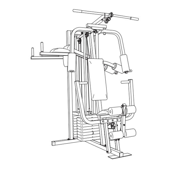
Page 4: Before You Begin
WEIDER ® serial number can be found on a decal attached to the 20CT will help you to achieve the specific results you weight system (see the front cover of this manual). want. Before reading further, please review the drawing... -
Page 5: Assembly
ASSEMBLY Make sure you have the following tools: Make Assembly Easier for Yourself • Two adjustable wrenches Everything in this manual is designed to • One standard screwdriver ensure that the weight system can be assem- bled successfully by anyone. Before begin- •... - Page 6 FRAME ASSEMBLY 1. Before beginning assembly, be sure that you have read and understand the information in the box above. High Side Press two 2” Outer Caps (51) onto the indicated locations on the Stabilizer (5). Press two 2” Inner Caps (27) into the indicated ends of the Stabilizer and the Base (4).
- Page 7 3. Press a 2” Inner Cap (27) into the Top Frame (55). Press a 1 3/4” Inner Cap (44) into each end of the crossbar on the Top Frame. Press two Round Inner Caps (96) into the top of the crossbar. Attach the Top Frame (55) to the Front Upright (42) with two 5/16”...
- Page 8 6. Press a Weight Tube Bumper (64) into the end of the other Weight Tube (63). Insert the Weight Tube into the rear stack of Weights (25). Be sure Holes that the pins on the Weight Tube are sitting in the pin grooves in the top Weight (refer to step 4).
- Page 9 9. Wet the handle of one Press Arm (46) with soapy water. Slide a 5” Plastic Grip (83) onto the han- dle. Press a 1” Round Inner Cap (49) into the other end of the handle. Press a 1 3/4” Inner Cap Handle (44) into the Press Arm.
- Page 10 12. Press two 1” x 2” Inner Caps (87) into the indicat- ed end of the Squat Arm (84). Attach the Squat Arm (84) to the VKR Upright (74) with a 3/8” x 5 1/2” Bolt (93) and a 3/8” Nylon Locknut (21).
- Page 11 15. Route the Medium Cable (58) around the “V”- Pulley (50) on the Right Arm (48). Be sure that the Cable is in the groove of the Pulley and that the Long Cable Trap (31) is positioned to hold the Cable in place. Tighten the 3/8” x 2 1/2” Bolt (86) and the 3/8”...
- Page 12 19. Route the Short Cable (23) around the 3 1/2” Pulley (15) attached to the upper hole in the Press Frame (17). Be sure that the Cable Trap (66) is in the “3 o’clock” position and that the Cable is routed around the Pulley as shown. Tighten the 3/8”...
- Page 13 22. Locate the Long Cable (72). Attach the Long Cable to the other Small “U”-Bracket (71) with a 1/4” Nylon Locknut (2) and a 1/4” Washer (10). Do not completely tighten the Nylon Locknut. It should be threaded onto the end of the Cable only a couple of turns, as shown in the inset drawing.
- Page 14 24. Wrap the Long Cable (72) around a 3 1/2” Pulley (15). Attach the Pulley and a Cable Trap (66) to the Squat Arm (84) with the 3/8” x 2 1/4” Bolt (94) and a 3/8” Jamnut (92). Be sure that the Jamnut is on the side shown and that the Cable Trap is positioned to hold the Cable in place.
- Page 15 27. Press a 1 1/2” Inner Cap (32) into the Seat Frame (36). Insert a 1/4” x 2” Carriage Bolt (38) into the center hole in the Seat Plate (37). Attach the Seat Plate to the Seat (13) with two 1/4” x 3/4” Screws (18). Insert the 1/4”...
-
Page 16: Adjustments
VKR ASSEMBLY 31. Press two 1 1/2” Inner Caps (32) into the ends of the Left and Right VKR Arms (79, 80). Attach the Left and Right VKR Arms (79, 80) to the VKR Upright (74) with two 5/16” x 3” Bolts (75) and two 5/16”... -
Page 17: Weight Resistance Chart
ADJUSTMENTS The instructions below describe how each part of the weight system can be adjusted. Refer to the exercise guide accompanying this manual to see how the weight system should be set up for each exercise. IMPOR- TANT: When attaching the lat bar or nylon strap, make sure that the attachments are in the correct start- ing position for the exercise to be performed. - Page 18 ATTACHING AND REMOVING THE SEAT To attach the Seat (13), set the bracket on the Seat Frame (36) onto the indicated pins on the Front Upright (42). Attach the Seat Frame to the Front Upright with the 5/16” x 2 3/4” Carriage Bolt (14) and the Seat Knob (40).
- Page 19 WEIGHT RESISTANCE CHART This chart shows the approximate weight resistance at each station. “Top” refers to the 6.5 lb. top weight. The other numbers refer to the 12.5 lb. weight plates. The butterfly arm resistance listed is the resistance for each butterfly arm.
-
Page 20: Trouble-Shooting And Maintenance
TROUBLE-SHOOTING AND MAINTENANCE Make sure all parts are properly tightened each time you use the weight system. Replace any worn parts immedi- ately. The weight system can be cleaned using a damp cloth and mild non-abrasive detergent. Do not use solvents. TIGHTENING THE CABLES Woven cable, the type of cable used on the weight system, can stretch slightly when it is first used. -
Page 21: Cable Diagram
CABLE DIAGRAM The cable diagram below shows the proper routing of the Long Cable (72), the Medium Cable (58), and the Short Cable (23). Use the diagram to be sure that the three cables and cable traps have been assembled cor- rectly. - Page 22 PART IDENTIFICATION CHART—Model No. WESY85311 R0802A 1/4" x 2" Machine Screw (81) 3/8" Nylon Locknut (21) 3/8" Washer (9) 3/8" Jamnut (92) 5/16" x 1 3/4" Bolt (24) 5/16" Washer (8) 5/16" Nylon Locknut (3) 1/4" x 3/4" Screw (18) 1/4"...
- Page 23 5/16" x 2 1/2" Bolt (22) 3/8" x 2 1/2" Bolt (86) 3/8" x 2 1/4" Bolt (94) 5/16" x 2 1/2" Carriage Bolt (1) 5/16" x 2 1/4" Bolt (33) 5/16" x 2 3/4" Bolt (11) 1/4" x 2 1/2" Screw (43) 5/16"...
- Page 24 1/2" x 17/32" Spacer (91) Round Inner Cap (96) 5/8" x 9/16" Spacer (7) 5/8" x 3/8" Spacer (76) 1" Round Inner Cap (49) 1/2" x 3/4" Spacer (61) 1" Round Cover Cap (70) 3/4" Round Inner Cap (34) 1" Inner Cap (6) 1"...
- Page 25 PART LIST—Model No. WESY85311 R0802A Key No. Qty. Description Key No. Qty. Description 5/16” x 2 1/2” Carriage Bolt “V”-Pulley 1/4” Nylon Locknut 2” Outer Cap 5/16” Nylon Locknut Chain Base Cable Clip Stabilizer Lat Bar 1” Inner Cap Top Frame 5/8”...
- Page 26 EXPLODED DRAWING—Model No. WESY85311 R0802A...
- Page 27 Friday, 6 a.m. until 6 p.m. Mountain Time (excluding holidays). To help us assist you, please be prepared to give the following information: 1. The MODEL NUMBER of the product (WESY85311) 2. The NAME of the product (WEIDER ® 20CT weight system) 3.
Need help?
Do you have a question about the 20ct and is the answer not in the manual?
Questions and answers