Pro-Form 520 Zlt Treadmill User Manual
Uk manual
Hide thumbs
Also See for 520 Zlt Treadmill:
- Manual (28 pages) ,
- Bedienungsanleitung (28 pages) ,
- Manuel de l'utilisateur (28 pages)
Table of Contents
Advertisement
Model No. PETL59711.0
Serial No.
Write the serial number in the space
above for reference.
Serial Number
Decal
QUESTIONS?
If you have questions, or if there are
missing parts, please contact us:
UNITED KINGDOM
Call: 08457 089 009
From Ireland: 053 92 36102
Website: www.iconsupport.eu
E-mail: csuk@iconeurope.com
Write:
ICON Health & Fitness, Ltd.
c/o HI Group PLC
Express Way
CASTLEFORD
WF10 5QJ
UNITED KINGDOM
AUSTRALIA
Call: 1800 993 770
E-mail: australiacc@iconfitness.com
Write:
ICON Health & Fitness
PO Box 635
WINSTON HILLS NSW 2153
AUSTRALIA
CAUTION
Read all precautions and instruc-
tions in this manual before using
this equipment. Save this manual
for future reference.
USER'S MANUAL
www.iconeurope.com
Advertisement
Table of Contents

Related Manuals for Pro-Form 520 Zlt Treadmill


Summary of Contents for Pro-Form 520 Zlt Treadmill
- Page 1 Model No. PETL59711.0 Serial No. USER’S MANUAL Write the serial number in the space above for reference. Serial Number Decal QUESTIONS? If you have questions, or if there are missing parts, please contact us: UNITED KINGDOM Call: 08457 089 009 From Ireland: 053 92 36102 Website: www.iconsupport.eu E-mail: csuk@iconeurope.com...
-
Page 2: Table Of Contents
Apply the decal in the location shown. Note: The decals may not be shown at actual size. PROFORM is a registered trademark of ICON IP, Inc. -
Page 3: Important Precautions
IMPORTANT PRECAUTIONS WARNING: To reduce the risk of serious injury, read all important precautions and instructions in this manual and all warnings on your treadmill before using your treadmill. ICON assumes no responsibility for personal injury or property damage sustained by or through the use of this product. - Page 4 20. Do not attempt to raise, lower, or move the the treadmill, and before performing the treadmill until it is properly assembled. (See maintenance and adjustment procedures ASSEMBLY on page 7 and HOW TO FOLD described in this manual. Never remove the AND MOVE THE TREADMILL on page 19.) motor hood unless instructed to do so by an You must be able to safely lift 45 lbs.
-
Page 5: Before You Begin
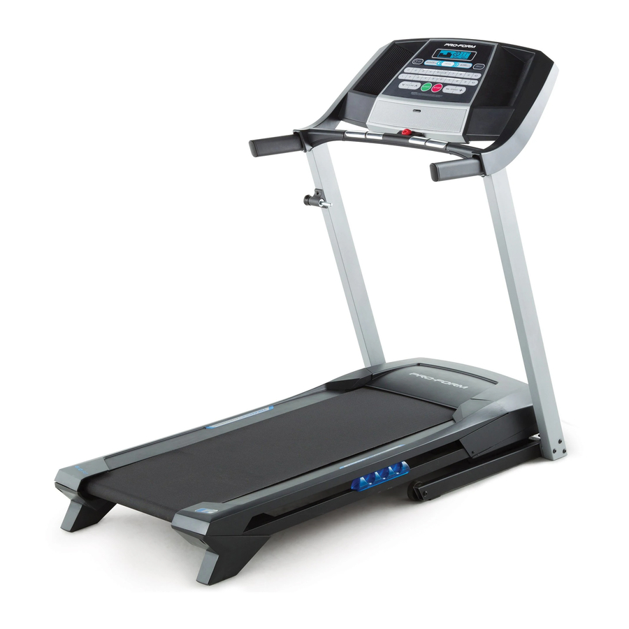
520 ZLT manual. To help us assist you, note the product model ® treadmill. The 520 ZLT treadmill provides an impressive number and serial number before contacting us. The selection of features designed to make your workouts model number and the location of the serial number at home more effective and enjoyable. -
Page 6: Part Identification Chart
PART IDENTIFICATION CHART Use the drawings below to identify small parts used for assembly. The number in parentheses below each draw- ing is the key number of the part, from the PART LIST near the end of this manual. The number following the key number is the quantity used for assembly. -
Page 7: Assembly
ASSEMBLY • Assembly requires two persons. • To identify small parts, see page 6. • Place all parts in a cleared area and remove the • Assembly requires the following tools: packing materials. Do not dispose of the packing the included hex keys materials until you finish all assembly steps. - Page 8 3. Identify the Right Upright (76), which is marked “Right.” Have a second person hold the Right Upright near the Base (74). See the inset drawing. Tie the wire tie in the Right Upright (76) securely around the end of the Upright Wire (63).
- Page 9 5. Identify the Right Handrail (64), which is marked “Right.” Remove the 5/16" x 3/4" Screw (5) and the 5/16" Star Washer (6) from the Right Handrail (64). Note: The Screw and the Star Washer will be used in step 6. Repeat this step for the Left Handrail (not shown).
- Page 10 8. Remove the four Screws (D) from the Left and Right Handrails (59, 64). Discard the Screws. 9. Attach the Console Crossbar (61) to the Left and Right Uprights (66, 76) with four #10 x 3/4" Screws (8) and four #10 Star Washers (23). Start all four Screws, and then tighten them.
- Page 11 10. With the help of a second person, hold the con- sole assembly near the Right Handrail (64). Connect the Upright Wire (63) to the console Console Assembly wire. See the inset drawing. The connectors should slide together easily and snap into place.
- Page 12 12. Have a second person hold the Frame (38) during the next three assembly steps. Attach the Latch Crossbar (91) to the Frame (38) with two 1/4" x 1 3/4" Screws (84). 13. Attach the Latch Bracket (82) on the end of the Storage Latch (85) to the Base (74) with two 3/8"...
-
Page 13: Operation And Adjustment
14. Attach the upper end of the Storage Latch (85) to the Latch Crossbar (91) with a 3/8" x 1 3/4" Bolt (68) and a 3/8" Nut (10). Move the treadmill to the desired location for use if you have not already done so (see HOW TO FOLD AND MOVE THE TREADMILL on page 19). - Page 14 CONSOLE DIAGRAM FEATURES OF THE CONSOLE To turn on the power, see page 15. To use the man- ual mode, see page 15. To use a preset workout, see The treadmill console offers a selection of features page 17. To use the information mode, see page 18. designed to make your workouts more effective.
-
Page 15: To Turn On Power
HOW TO TURN ON THE POWER HOW TO USE THE MANUAL MODE IMPORTANT: If the treadmill has been exposed to 1. Insert the key into the console. cold temperatures, allow it to warm to room tem- perature before turning on the power. If you do not See HOW TO TURN ON THE POWER at the left. - Page 16 4. Change the incline of the treadmill as desired. burned, or the speed of the walking belt. Press the Priority Display button repeatedly until the upper To change the incline of the treadmill, press the display shows the information that you are most Incline increase and decrease buttons or one of interested in viewing.
-
Page 17: To Use A Preset Workout
HOW TO USE A PRESET WORKOUT programmed for the next segment, the speed and/ or incline setting will flash in the display to alert you. 1. Insert the key into the console. The treadmill will then automatically adjust to the speed and incline settings for the next segment. See HOW TO TURN ON THE POWER on page 15. The workout will continue in this way until the last 2. - Page 18 THE INFORMATION MODE An “E” for English miles or an “M” for metric kilometers will appear in the lower right display. Press the Speed The console features an information mode that keeps increase button to change the unit of measurement, if track of treadmill usage information and allows you to desired.
-
Page 19: How To Fold And Move The Treadmill
HOW TO FOLD AND MOVE THE TREADMILL HOW TO FOLD THE TREADMILL HOW TO MOVE THE TREADMILL Before folding the treadmill, adjust the incline to Before moving the treadmill, fold it as described at the lowest position. If you do not do this, you may the left. -
Page 20: Troubleshooting
TROUBLESHOOTING Most treadmill problems can be solved by following d. If the treadmill still will not run, please see the front the simple steps below. Find the symptom that cover of this manual. applies, and follow the steps listed. If further assis- tance is needed, see the front cover of this manual. - Page 21 Locate the Reed Switch (33) and the Magnet (32) b. If the walking belt is overtightened, treadmill per- on the right side of the Pulley (31). Turn the Pulley formance may decrease and the walking belt may until the Magnet is aligned with the Reed Switch. become damaged.
- Page 22 SYMPTOM: The walking belt is not centered SYMPTOM: The walking belt slips when walked on between the foot rails. IMPORTANT: If the walking belt rubs against the foot rails, the walking belt a. First, remove the key and UNPLUG THE POWER may be damaged.
-
Page 23: Exercise Guidelines
EXERCISE GUIDELINES Burning Fat—To burn fat effectively, you must exer- WARNING: cise at a low intensity level for a sustained period of Before beginning this time. During the first few minutes of exercise, your or any exercise program, consult your physi- body uses carbohydrate calories for energy. -
Page 24: Part List
PART LIST Model No. PETL59711.0 R0312A Key No. Qty. Description Key No. Qty. Description #8 x 1/2" Ground Screw Motor Hood 3/8" x 3 1/4" Screw Incline Motor 3/8" Star Washer Lift Frame Bushing #8 x 3/4" Screw Lift Frame 5/16"... -
Page 25: Exploded Drawing
EXPLODED DRAWING A Model No. PETL59711.0 R0312A... - Page 26 EXPLODED DRAWING B Model No. PETL59711.0 R0312A...
- Page 27 EXPLODED DRAWING C Model No. PETL59711.0 R0312A 10 75...
-
Page 28: Ordering Replacement Parts
ORDERING REPLACEMENT PARTS To order replacement parts, please see the front cover of this manual. To help us assist you, be prepared to pro- vide the following information when contacting us: • the model number and serial number of the product (see the front cover of this manual) • the name of the product (see the front cover of this manual) • t he key number and description of the replacement part(s) (see the PART LIST and the EXPLODED DRAWING near the end of this manual) RECYCLING INFORMATION This electronic product must not be disposed of in municipal waste.
Need help?
Do you have a question about the 520 Zlt Treadmill and is the answer not in the manual?
Questions and answers