
Related Manuals for Windsor chariot iExtract CE24


Summary of Contents for Windsor chariot iExtract CE24
- Page 1 ® iExtract ® Operating Instructions (ENG) MODELS: CE24 CE24X CEE24 10060140 10060150 10060160 Read these instructions before using the machine 86037880-BW 11/29/12...
- Page 2 Warranty Registration Thank you for purchasing a Windsor product. Warranty registration is quick and easy. Your registration will allow us to serve you better over the lifetime of the product. To register your product go to: www.windsorind.com/WarrantyRegistration.aspx...
-
Page 3: Table Of Contents
TABLE OF CONTENTS GROUP PARTS LIST Machine Data Log/Overview........2 Table Of Contents ..........3 Bumper .............. 5-1 Control Pane-Upper .......... 5-3 HOW TO USE THIS MANUAL Control Panel-Lower.......... 5-5 Control Panel Housing ........5-7 How To Use This Manual........1-1 Decal ..............5-9 Frame-Lower ............. -
Page 4: How To Use This Manual
The MAINTENANCE section contains preventive maintenance to keep the machine and its Parts may be ordered from authorized Windsor components in good working condition. They are dealers. When placing an order for parts, the listed in this general order: machine model and machine serial number are important. -
Page 5: Important Safety Instructions
IMPORTANT SAFETY INSTRUCTIONS When using an battery powered appliance, basic precaution must always be followed, including the following: READ ALL INSTRUCTIONS BEFORE USING THIS MACHINE. To reduce the risk of fire, electric shock, or injury: Use only indoors. Do not use outdoors or expose to rain. Use only as described in this manual. -
Page 6: Hazard Intensity Level
WHEN SERVICING MACHINE: Avoid moving parts. Do not wear loose clothing: jackets, shirts, or sleeves when working on the machine. Use Windsor approved replacement parts. Batteries emit hydrogen gas. Explosion or fire can result. Keep sparks and open flame away. Keep battery compartment open during charging. -
Page 7: Safety Label Location
SAFETY LABEL LOCATION NOTE: These drawings indicate the location of safety labels on the machine. If at any time the labels become illegible, promptly replace them. 86244300 PRV 500955 WARNING LABEL 86244310 PRV 500956 CAUTION LABEL 86252520 PRV 80885 BATTERY CAUTION 86037880 CHARIOT EXTRACTOR 01/16/07... -
Page 8: Technical Specifications
TECHNICAL SPECIFICATIONS ITEM DIMENSION/CAPACITY Nominal Power 2952 W Rated Voltage 36 Volts DC Rated Amperage 82 amps Batteries 3 X12 Volt 195-215 AH @ 20 hr. rate Battery Compartment Dimensions 21 in. x 16 in. x 17 in. tall (533mm x 406mm x 432mm) Propelling Motor .75 HP (560 W) Mass (GVW) - Page 9 TECHNICAL SPECIFICATIONS ITEM MEASURE Height 50.6 inches (1285 mm) Length 52.5 inches (1330 mm) Width 26.5 inches (670 mm) Width of scrub path 23 inches (585 mm) WIDTH LENGTH SPECIAL NOTES: The weighted root mean square acceleration at the The sound pressure level at the operator’s ear was operator’s arms was measured to be below 2.5m/s measured to be 70 dBA.
-
Page 10: How This Machine Works
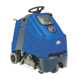
HOW THIS MACHINE WORKS The Chariot iExtract® is a battery powered, self- The function of the operator control system is to propelled Carpet Extractor intended for commercial control the direction and speed of the machine. The use. The machine is designed to apply a cleaning directional control system consists of the direction solution onto carpeted floor, sweep and scrub the control switch, throttle pedal, speed control switch,... -
Page 11: Components
COMPONENTS 1. Control Panel-Drive 7. Scrub Deck 2. Control Panel-Scrub 8. Vacuum Shoes 3. Control Housing 9. Recovery Dome 4. Pedal Platform 10. Recovery Drain Hose 5. Rear Cover 11. Solution Cover 6. Tank 12. Solution Drain Hose 86037880 CHARIOT EXTRACTOR 01/16/07... -
Page 12: Drive Controls
DRIVE CONTROLS 86037880 CHARIOT EXTRACTOR 01/16/07... - Page 13 DRIVE CONTROLS Key Switch Drive Reset Switch Emergency Stop/Brake Switch Horn Button Directional Control Switch Steering Wheel Throttle Pedal Battery Discharge Operator Presence Pedal- Indicator Prior to Serial Number (11*) Hour Meter Speed Control Switch 1. KEY SWITCH Controls the power for machine functions. To turn the machine power on, rotate key clockwise.
- Page 14 DRIVE CONTROLS 4. THROTTLE PEDAL Controls the speed of the vehicle within the speed control setting selected. Pressing the pedal causes the machine to travel in the direction selected by the Directional Control Switch. To increase speed, increase pressure on the pedal. To decrease speed, decrease pressure on the pedal.
- Page 15 DRIVE CONTROLS 10. BATTERY DISCHARGE INDICATOR Indicates the charge level of the batteries. The meter display is divided into 10 vertical bars. Bars illuminated on the far right indicate full charge. Bars flashing near the left side indicate the batteries should be recharged. Further operation of the machine could damage the machine or the batteries.
-
Page 16: Scrub Controls
SCRUB CONTROLS 1. Vacuum Shoe Lift Lever 3. Solution Control Switch 2. Scrub Deck Actuator Switch 4. Solution Accessory Tool Hookup 86037880 CHARIOT EXTRACTOR 01/16/07... - Page 17 SCRUB CONTROLS 1. VACUUM SHOE Raises and lowers the vacuum shoes, and turns the vacuum motors on and off. To lower vacuum shoes and start vacuum motors, lift the lever from its raised position. To raise vacuum shoes and stop vacuum motors, lift the lever from its lowered position. 2.
-
Page 18: Machine Operation
MACHINE OPERATION PRE-RUN MACHINE INSPECTION Do a pre-run inspection to find possible problems that could cause poor performance or lost time from EMERGENCY STOP PROCEDURES breakdown. Follow the same procedure each time to avoid missing steps. 1. Release the throttle pedal by lifting right foot. NOTE: See maintenance section for pre-run 2. -
Page 19: Filling Solution Tank
MACHINE OPERATION FILLING SOLUTION TANK NORMAL SCRUBBING FOR SAFETY: Before leaving or servicing Plan the scrubbing pattern in advance. machine; stop on level surface, turn off machine For efficient operation, the runs should be the and remove key. longest possible without turning, stopping, or raising or lowering scrub deck. -
Page 20: To Begin Scrubbing
MACHINE OPERATION PRIMING PUMP TO BEGIN SCRUBBING If the solution system has gone dry or has been When operating the machine around people, pay unused for a period of time, it may be necessary to close attention for unexpected movement. Use follow the pump priming procedure. -
Page 21: To Stop Scrubbing
MACHINE OPERATION TO STOP SCRUBBING Remove the recovery tank dome. Flush the recovery bag out with clean water. Do not use 1. Raise the scrub deck, turn off scrub brushes. water hotter than 140°F (60°C) to clean tank. Damage may occur. 2. - Page 22 NOTES: 86037880 CHARIOT EXTRACTOR 01/16/07 3-15...
-
Page 23: Maintenance
SERVICE SCHEDULE AFTER EACH BEFORE EACH MAINTENANCE WORK WORK PERIOD PERIOD Check water level of batteries after charging; add distilled water if necessary. (Wet cell only) Check that dome and cover seal tightly. Visually check for damaged or worn tires. Check brushes for proper installation. -
Page 24: Batteries
MAINTENANCE- BATTERIES 4. Batteries 1. Rear Cover Retainer Knob 5. Battery Tray 2. Rear Cover 6. Battery Tray Latch 3. Battery Connector-Machine 86037880 CHARIOT EXTRACTOR 01/16/07... - Page 25 MAINTENANCE-BATTERIES BATTERIES When servicing machine, avoid contact with battery The batteries provide the power to operate the acid. machine. The batteries require regular maintenance to keep them operating at peak efficiency. Batteries emit hydrogen gas. Explosion or fire can The machine batteries will hold their charge for long result.
- Page 26 MAINTENANCE-BATTERIES CHECKING BATTERY SPECIFIC GRAVITY CHARGING BATTERIES Use a hydrometer to check the battery specific When servicing machine, gravity. avoid contact with battery acid. Batteries emit hydrogen gas. Explosion or fire can Battery Check result. Keep sparks and open flame away. Keep covers open when charging.
- Page 27 MAINTENANCE-BATTERIES CHANGING BATTERIES 1. Replace the battery caps, and leave them in place while charging. Stop the machine in a clean area next to the charger. Turn off machine. 2. Unplug the battery connector from the machine. FOR SAFETY: Before leaving or servicing the FOR SAFETY: When charging, connect the machine;...
-
Page 28: Vacuum Shoes
MAINTENANCE-VACUUM SHOES 1. Vacuum Shoes 2. Vacuum Shoes Glides 3. Vacuum Shoe Retainer Knobs 86037880 CHARIOT EXTRACTOR 01/16/07... - Page 29 MAINTENANCE - VACUUM SHOES VACUUM SHOES TO CLEAN VACUUM SHOES The dual offset vacuum shoes are designed to 1. With the vacuum shoes in the raised position, extract soiled solution from the carpet. The plastic turn key switch “off”. vacuum shoe glides minimize damage to carpet and flooring.
- Page 30 MAINTENANCE-SCRUB DECK 1. Hopper 5. Brush Door 2. Hopper Retainer Plate 6. Motor Assembly Jack Screw 3. Scrub Brush Motor 7. Lower Links 4. Scrub Deck Lift Actuator 8. Brush Pressure Adjustment 86037880 CHARIOT EXTRACTOR 01/16/07...
- Page 31 MAINTENANCE-SCRUB DECK SCRUB HEAD SCRUB BRUSH REPLACEMENT The dual cylindrical scrub head is designed to 1. Lift the drive side of the brush and push it onto sweep and scrub the carpet. The brushes, turning in drive hub until a positive stop is felt. The brush a counterclockwise rotation, pick up the debris and door cannot be installed until the brush is fully throw it into a removable hopper, and raise the pile...
-
Page 32: Scrub Deck
MAINTENANCE-SCRUB DECK SCRUB DECK ADJUSTMENT ADJUSTMENT OF INDIVIDUAL BRUSHES Scrub deck adjustment consists of three types of The brush pattern is adjusted from the motor side adjustments. The first is to insure the individual only of both brushes. brushes make the same width pattern end to end. Any tapered brush pattern should be adjusted out. - Page 33 MAINTENANCE-SCRUB DECK Do not use a pressure BRUSH MOTOR CARBON BRUSH washer to clean around REPLACEMENT the brush motors. Use tap pressure only. 1. Scribe alignment mark on motor barrel to motor TO REPLACE SCRUB BRUSH MOTORS cap. Remove two bolts. 1.
- Page 34 MAINTENANCE-SCRUB DECK ACTUATOR SCRUB DECK SCRUB DECK ACTUATOR ADJUSTMENT REMOVAL/REPLACEMENT The actuator will need to be adjusted when FOR SAFETY: Before leaving or servicing replaced. machine, stop on a level surface. Turn off machine. To adjust the actuator: 1. Lower scrub deck. 1.
-
Page 35: Circuit Protection
MAINTENANCE–CIRCUIT PROTECTION CIRCUIT BREAKERS CIRCUIT BREAKERS Circuit breakers interrupt the flow of power in the event of an electrical overload. When a circuit 30 Amp. Protects the left vacuum motor breaker is tripped, reset it by pressing the circuit. exposed button. If a circuit breaker continues to trip, the cause of the electrical overload should 30 Amp. -
Page 36: Solution Strainer & Pump
MAINTENANCE-SOLUTION STRAINER & PUMP 1. Solution Strainer – Coarse 4. Solenoid Valve 2. Solution Strainer – Fine 5. Jets 3. Pump 6. Shut-off Valve 86037880 CHARIOT EXTRACTOR 01/14/08 4-14... - Page 37 MAINTENANCE – SOLUTION STRAINER & PUMP SOLUTION STRAINER – COARSE 4. Reverse steps to install. Located in bottom of tank. The coarse strainer 4. SOLENOID VALVE protects the finer strainer from large debris. If the fine strainer is clean and the pump and The solenoid valve is mounted on the front of solenoid valve are not working, then check the the scrub deck, on right side.
-
Page 38: Vacuum & Float Shut-Off
MAINTENANCE-VACUUM & FLOAT SHUT-OFF 1. Recovery tank float shut-off 2. Vacuum motor 86037880 CHARIOT EXTRACTOR 01/16/07 4-16... - Page 39 MAINTENANCE – VACUUM & FLOAT SHUT-OFF RECOVERY TANK FLOAT SHUT-OFF FOR SAFETY: before leaving or servicing machine, When water is no longer being vacuumed from the stop on a level surface, turn off machine and floor and the vacuum fan is operating, the ball float disconnect power.
-
Page 40: Drive Motor & Brake
MAINTENANCE- DRIVE MOTOR & BRAKE Drive motor Parking brake 86037880 CHARIOT EXTRACTOR 10/29/08 4-18... - Page 41 MAINTENANCE-DRIVE MOTOR & BRAKE ELECTRIC PARKING BRAKE ENGAGEMENT To disengage brake: FOR SAFETY: Before leaving or servicing machine, stop on a level surface, turn off machine and remove key. Electric Brake Engagement This machine is equipped with an electric parking brake.
- Page 42 MAINTENANCE-DRIVE MOTOR & BRAKE DRIVE MOTOR CARBON BRUSH REPLACEMENT 7. Install new brush and reinstall connecting screw and lead. Do not use a pressure washer to clean around 8. When all new brushes are installed. Place all in the motors. Use tap pressure only. retracted position, held into brush holder by spring tension.
-
Page 43: Bag Replacement
MAINTENANCE-BAG REPLACEMENT REPLACING BAG REMOVING BAG 1. Install mandrel in bottom of bag. 1. Disconnect batteries and make sure parking brake is not overridden. 2. Place new bag in tank making sure hole for strainer basket is oriented properly. 2. Under left front side of machine loosen hose clamp on recovery dump hose. - Page 44 MAINTENANCE-TRANSPORTATION PUSHING MACHINE PREPARATION FOR LOADING /UNLOADING TRAILER The machine may be pushed for short distances at speeds not to exceed 5 mph. Be careful to avoid Before loading or unloading machine from trailer, damaging machine. The machine may be pushed by remove scrub brushes and vac shoes to eliminate hand from the rear.
- Page 45 MAINTENANCE-TROUBLESHOOTING PROBLEM CAUSE SOLUTION No power to machine Battery disconnected Check all battery cable connections Emergency shut-off activated Reset Battery cables corroded Clean connections Faulty key switch Replace switch Little or no propel Low battery charge Charge batteries Machine turned on with pedal not in Allow pedal to return to neutral.
-
Page 46: Machine Troubleshooting
MACHINE TROUBLESHOOTING PROBLEM CAUSE SOLUTION Vacuum motor(s) not running, or run Circuit breaker tripped Reset circuit breaker slowly Faulty vacuum circuit or switch Check wires, connections and switch Worn vacuum motor brushes Replace brushes, check commutator Vacuum shoes will not go up/down Faulty cables or pulleys Repair/replace cables and pulleys Poor scrubbing performance... - Page 47 MACHINE TROUBLESHOOTING- CONTROLLER FAULT CODES PROPEL CIRCUIT BOARD TROUBLESHOOTING Curtis 1228 LED DIAGNOSTICS- Basic and Cylindrical During normal operation, with no faults present, the status LED is steadily on. If the controller detects a fault, the status LED provides two types of information. First, it displays a slow flash (2 Hz) or a fast flash (4 Hz) to indicate the severity of the fault.
- Page 48 MACHINE TROUBLESHOOTING- CONTROLLER FAULT CODES PROGRAMMER LCD EXPLANATION POSSIBLE CAUSE CODE DISPLAY PROC/WIRING FAULT HPD fault present for 1. Misadjusted throttle. >10 sec. 2. Broken throttle pot or throttle mechanism. BRAKE ON FAULT brake On fault 1. Electromagnetic brake driver shorted.
- Page 49 PARTS 86037880 CHARIOT EXTRACTOR 01/16/07...
-
Page 50: Bumper
BUMPER 10 7 7 10 9 86037880 CHARIOT EXTRACTOR 01/16/07... - Page 51 BUMPER SERIAL NO. PART NO. PRV NO. DESCRIPTION FROM NOTES: 86276890 70752 SCR, 5/16-18X3/4 PTHMS SS 86007070 70849 SCR, #12 X 1.25 PPHMS SS 86063230 140813 BUMPER , LEFT 86063240 140814 BUMPER, RIGHT 86071020 140783 BRKT, FRONT BUMPER 86270830 57023 NUT, 5/16-18 HEX NYLOCK SS 86010670 87029...
-
Page 52: Control Pane-Upper
CONTROL PANEL- UPPER 86037880 CHARIOT EXTRACTOR 01/16/07... - Page 53 CONTROL PANEL - UPPER SERIAL NO. PART NO. PRV NO. DESCRIPTION NOTES: FROM 86002010 14942 BOOT, 3/8 CIRCUIT BREAKER 86008900 80845 BOOT, SEAL-PUSH BUTTON 7/16-28 86007130 72128 SWITCH, DPDT 2-POSITION ROCKER 86007140 72130 SWITCH, SPST 2-POSITION ROCKER 86007180 72160 SWITCH, EMERGENCY STOP 86007190 72161 SWITCH KEY DPST...
-
Page 54: Control Panel-Lower
CONTROL PANEL- LOWER 86037880 CHARIOT EXTRACTOR 01/16/07... - Page 55 CONTROL PANEL-LOWER SERIAL NO. PART NO. PRV NO. DESCRIPTION NOTES: FROM 86223740 70872 SCR, 1/4-20 X .59 PPHMS SS C 86273820 70019 SCR, 1/4-20 X 1.25 HHCS 86277480 70850 SCR, 5/16-18 X 1/2 PTHMS SS 86070720 140728 BRKT, BATT CONN, BASIC 86008760 80682 CONN, 175 DCA GRY W/O TERMS...
-
Page 56: Control Panel Housing
CONTROL PANEL HOUSING 86037880 CHARIOT EXTRACTOR 01/16/07... - Page 57 CONTROL PANEL HOUSING SERIAL NO. PART NO. PRV NO. DESCRIPTION NOTES: FROM 86005810 57245 NUT, 1/4-20 HEX NYLOCK SS 86290540 SCR, 10-32 X 1/2 TORX SS BLK NP 86277480 70850 SCR, 5/16-18 X1/2 PTHMS SS 86070710 140726 BRKT, LEFT CONSOLE MOUNT 86237900 35278 GASKET, .125 X .25W X 23L...
-
Page 58: Decal
DECAL 86037880 EXTRACTOR 01/06/09... - Page 59 DECAL SERIAL NO. PART NO. PRV NO. DESCRIPTION NOTES: FROM 86004970 50990 LABEL, WINDSOR LOGO DOMED 86244820 501230 DECAL, CHARIOT IEXTRACT LT 86244190 500882 LABEL, PANEL BASIC LEFT 86243990 500780 LABEL, COVER PANEL 86244510 501108 LABEL, PANEL, EXTRACTOR, RT OPEN...
-
Page 60: Frame-Lower
FRAME-LOWER 5-11 86037880 CHARIOT EXTRACTOR 01/16/07... - Page 61 FRAME-LOWER SERIAL NO. PART NO. PRV NO. DESCRIPTION FROM NOTES: 86070750 140731 BRKT, LINKAGE, LEFT 86071130 140812 BRKT, TIP BRACE, LEFT, REAR 86070760 140733 BRKT, BRACE, LEFT FRONT 86276070 70593 SCR, 5/16-18 X 3/4 CARRIAGE SS 86092500 34428 FRAME, MAIN 86197040 57264 NUT, 5/16-18 HEX ACORN PLTD...
-
Page 62: Frame-Upper
FRAME-UPPER VACUUM SHOE LIFT GROUP 86037880 CHARIOT EXTRACTOR 01/16/07 5-13... - Page 63 FRAME-UPPER SERIAL NO. PART NO. PRV NO. DESCRIPTION FROM NOTES: 86091610 140129 BRKT, HORIZ ELECT, EXTRACTOR 86270830 57023 NUT, 5/16-18 HEX NYLOCK SS 86010670 87029 WASHER, 5/16 FLAT SS 86276070 70593 SCR, 5/16 X 3/4 CARRIAGE SS 86083080 66437 PLATE, VERT BEARING SUPPORT 86277460 70847 SCR, 5/16-18 X 5/8 BSHCS SS...
- Page 64 PEDAL PLATFORM-From Serial Number (11*) 86037880 CHARIOT EXTRACTOR 03/31/10 5-15A...
- Page 65 PEDAL PLATFORM-From Serial Number (11*) SERIAL PART NO. PRV NO. DESCRIPTION NOTES FROM 86233170 20054 CLAMP, 3/8 NYLON UL/CSA 86264920 27049 CABLE TIE, .19 X 7 UL/CSA 86222510 34430 PEDAL, THROTTLE 86221850 34433 LINK, THROTTLE 86136310 57086 NUT, M5 HEX 86312820 BRACKET, POT, SPEED 86288720...
- Page 66 PEDAL PLATFORM-To Serial Number (11*) 86037880 CHARIOT EXTRACTOR 11/18/09 5-16A...
- Page 67 PEDAL PLATFORM-To Serial Number (11*) SERIAL NO. PART NO. PRV NO. DESCRIPTION FROM NOTES: 86217650 34432 DIVIDER 86222700 34429 PLATFORM 86216380 140713 BUSHING, 8MM X 10LG CLY 86007110 72123 SWITCH, 25A SPST 125-250V SNAP 86279720 87248 WASHER, M4 INT STAR 86272040 57503 NUT, M3.5 X 2.8 HEX...
-
Page 68: Pedal Platform (From Sn)
PEDAL PLATFORM 86037880 CHARIOT EXTRACTOR 01/16/07 5-17... -
Page 69: Pedal Platform (To Sn)
PEDAL PLATFORM SERIAL NO. PART NO. PRV NO. DESCRIPTION FROM NOTES: 86248920 66487 PIN, CLEVIS 1/2 X 2.25 86274690 70258 SCR, 5/16-18 X 1.5 HHCS GR5PLT 86264920 27049 CABLE TIE, 7” UL/CSA 86231070 730328 BUMPER, 1 X 1.375 RUBBER 86010670 87029 WASHER, 5/16 FLAT SS 86259430... -
Page 70: Rear Cover
REAR COVER 5-19 86037880 CHARIOT EXTRACTOR 04/16/09... - Page 71 REAR COVER SERIAL NO. PART NO. PRV NO. DESCRIPTION NOTES: FROM 86276780 70728 SCR, 5/16-18 X 3/4 HHCS SS 86279130 87083 WASHER, 5/16 SPLIT LOCK PLTD 86010670 87029 WASHER, 5/16 FLAT SS 86031790 270701 COVER, REAR, BASIC 86005860 57273 NUT, 1/4-20 X 12MM HEX BARREL 86228980 09152 BEARING FLANGED .377ID X .505OD...
- Page 72 SCRUB DECK HOSE ROUTING SEE DETAIL 'A' FROM PUMP OUTLET FROM MAIN HARNESS DETAIL 'A' 86037880 CHARIOT EXTRACTOR 09/13/08 5-21...
-
Page 73: Scrub Deck
SCRUB DECK SERIAL NO. PART NO. PRV NO. DESCRIPTION FROM NOTES: 86281150 39282 HOSE, 3/8 ID WIRE BOUND X 7” 86233150 20042 CLAMP, 3/8 HOSE (D-SLOT) 86281100 39274 HOSE, 1/2ID WIRE BOUND X 7” 86197760 78308 TEE, 1/4 STREET 86010730 87088 WASHER, 5/8 ID X 1.18 X .06 SS 86005580... -
Page 74: Scrub Deck Motors
SCRUB DECK MOTORS 5-23 86037880 CHARIOT EXTRACTOR 01/16/07... - Page 75 SCRUB DECK MOTORS SERIAL NO. PART NO. PRV NO. DESCRIPTION FROM NOTES: 86277880 70855 SCR, M8-1.25 X 35 LG SHCS SS 86222330 57504 NUT, M8 -1.25 HEX JAM SS 86279790 87489 WASHER, M8 (THICK) FLAT SS 86137310 87098 WASHER, M8 SPLIT LOCK 86217710 29268 DOOR, CYLINDRICAL BRUSH...
-
Page 76: Scrub Deck Lift Actuator
SCRUB DECK LIFT ACTUATOR 86037880 CHARIOT EXTRACTOR 05/11/07 5-25... - Page 77 SCRUB DECK LIFT ACTUATOR SERIAL NO. PART NO. PRV NO. DESCRIPTION FROM NOTES: *(1) 86011950 ACTUATOR, 36VDC, 3.5 IN STRK WAS 05250 86248980 81438 PIN, CLEVIS 3/8 X 1.75 PLTD 86006910 70443 SCR, 1/4-20 X 5/8 SHCS 86090330 87258 WASHER, .804ID X 1.25OD X .179 86278400 730351 SPRING, COMP., 1.10 OD X 2.25 L X 148...
-
Page 78: Scrub Deck Lift Linkage
SCRUB DECK LIFT LINKAGE 86037880 CHARIOT EXTRACTOR 02/10/07 5-27... - Page 79 SCRUB DECK LIFT LINKAGE SERIAL NO. PART NO. PRV NO. DESCRIPTION FROM NOTES: 86276070 70593 SCR, 5/16-18 X 3/4 CARRIAGE SS 86272380 66217 PIN, CLEVIS 3/8 X .75 PLTD 86010770 87143 WASHER, 7/16 ID X 1 D X .08 FLT SS 86005630 57022 NUT, 3/8-16 HEX NYLOCK THIN SS...
-
Page 80: Solution
SOLUTION TO TANK TO VALVE FROM STRAINER SEE DETAIL 'A' TO SCRUB DECK DETAIL ' B ' TO TANK CLOSED OPEN DETAIL ' B ' DETAIL 'A' BOTTOM VIEW 86037880 CHARIOT EXTRACTOR 07/24/08 5-29... - Page 81 SOLUTION SERIAL NO. REF PART NO. PRV NO. QTY DESCRIPTION NOTES: FROM 86197940 40027 HOSEBARB, 3/8MPT X 1/2 OD 90D DL 86233150 20042 CLAMP, 3/8 HOSE (D-SLOT) 86270990 57090 NUT, 10-32 HEX NYLOCK SS 86006100 65176 PUMP ASM, 36 V ACCESSORY 86010650 87018 WASHER, #10 X 6/16 OD...
-
Page 82: Steering
STEERING 86037880 CHARIOT EXTRACTOR 01/16/07 5-31... - Page 83 STEERING SERIAL NO. PART NO. PRV NO. DESCRIPTION FROM NOTES: 86271610 57228 NUT, 5/8-16 HEX NYLOCK THN 86234810 27945 COVER, STEERING WHEEL 86259610 730117 WHEEL, STEERING 40 SPLINE HUB 86224050 730318 SHAFT, UPPER STEERING 86228790 09111 BEARING, FLANGE .88ODX.75IDX.75 86091740 140720 BRKT, UPPER STEERING 86270830...
-
Page 84: Tank
TANK 5-33 86037880 CHARIOT EXTRACTOR 12/12/08... - Page 85 TANK SERIAL NO. PART NO. PRV NO. DESCRIPTION FROM NOTES: 86221900 54198 MANDREL, BAG 86006470 67513 RETAINER, BACK BAG 86001510 140712 BAG, INNER TANK, EXT. 86003710 34447 FLAP, TANK DEBRIS 86006480 67514 RETAINER, MAIN BAG 86010630 87013 WASHER, 1/4 ID X 5/8 OD SS 86271940 57299 NUT, 1/4-20 ACORN SS...
-
Page 86: Vacuum
VACUUM 86067880 CHARIOT EXTRACTOR 01/16/07 5-35... - Page 87 VACUUM SERIAL NO. PART NO. PRV NO. DESCRIPTION FROM NOTES: 86236540 34437 FOAM, POLY, 1/2 X 2 CURVED W/ADH 86238040 36243 GASKET, .25 T X .75 W X 24 L 86236530 34436 FOAM, POLYESTER, 1X3X18 86090140 270139 VAC CHANNEL COVER 86082110 62913 PLATE, CHAIN GUARD LT...
-
Page 88: Vacuum Shoes
VACUUM SHOES 86037880 CHARIOT EXTRACTOR 06/29/09 5-37... - Page 89 VACUUM SHOES REF PART NO. PRV NO. QTY DESCRIPTION SERIAL NO. FROM NOTES: 86006580 70085 10 SCR, 1/4-20 X 1/2 PPHMS SS 86075450 27246 COVER, VAC SHOE 86237910 35279 GASKET, VAC SHOE OUTER 86237920 35280 GASKET, 5.0 OD X 2.0 ID X .50T 86237930 35281 GASKET, VAC SHOE RIGHT...
-
Page 90: Vacuum Shoes Lift
VACUUM SHOES LIFT 86037880 CHARIOT EXTRACTOR 11/15/08 5-39... - Page 91 VACUUM SHOES LIFT REF PART NO. PRV NO. QTY DESCRIPTION SERIAL NO. FROM NOTES: 86276690 70715 SCR, 5/16-18 X 1.75 CARR SS 86278330 70641 SHOULDER BOLT, 3/8OD X 3/8L SS 86224370 730335 SPACER, 1 OD X .391 ID X .500 86259420 87232 WASHER, THRUST .51ID X 1 OD...
-
Page 92: Vacuum Shoe Lift Handle
VACUUM SHOE LIFT HANDLE 86037880 CHARIOT EXTRACTOR 08/14/07 5-41... - Page 93 VACUUM SHOE LIFT HANDLE SERIAL NO. PART NO. PRV NO. DESCRIPTION FROM NOTES: 86238360 36215 GRIP, 3/16 X 1.0 ORANGE 86076610 38319 HANDLE, LIFT 86257120 72192 SWITCH, DPST SNAP ACTION 86008650 80604 COTTER, 1/4” RING 86279450 87161 WASHER, #6 FLAT SAE 86277490 70851 SCR, #6-32 X 1.38 PPHMS...
-
Page 94: Vacuum Hoses
VACUUM HOSES TO DOME 86037880 CHARIOT EXTRACTOR 01/24/09 5-43... - Page 95 VACUUM HOSES SERIAL NO. PART NO. PRV NO. DESCRIPTION FROM NOTES: 86240320 39729 HOSE ASM, 1.5 BLK VAC X 36 86177050 03-000176 CLAMP, HOSE #20 86320330 HOSE ASM, 1.5 BLK VAC X 12 86003010 27759 CUFF, HOSE 1.5” BLK A 2161 86264950 27746 CABLE TIE, .19 W X 11.5L BLK...
-
Page 96: Wheel-Front Drive
WHEEL-FRONT DRIVE, GEAR GEAR REPLACEMENT KIT 86037880 CHARIOT EXTRACTOR 10/21/11 5-45... - Page 97 WHEEL-FRONT DRIVE, GEAR SERIAL NO. PART NO. PRV NO. DESCRIPTION FROM NOTES: 86275190 70377 SCR, 3/8-16 X 1.25 HHCS SS 86010790 87163 WASHER, 3/8 SPLIT LOCK PLTD 86002830 27196 CABLE TIE, .375 X 24.7 86006170 66031 PIN, ROLL 1/8” X 3/4”L 86264930 27050 CABLE TIE, 3.5”...
-
Page 98: Wheel-Rear
WHEEL-REAR 86037880 CHARIOT EXTRACTOR 01/16/07 5-47... - Page 99 WHEEL-REAR SERIAL NO. PART NO. PRV NO. DESCRIPTION FROM NOTES: 86259950 89276 WHEEL, 10X2.5X.787ID BEARINGS 86008710 80623 RING, ¾” EXT SNAP H-D 86232130 17309 CAP, 2.75 ID X 1.0 L BLK VINYL 5-48 86037880 CHARIOT EXTRACTOR 01/16/07...
-
Page 100: Wiring-Batteries
WIRING-BATTERIES 5-49 86037880 CHARIOT EXTRACTOR 08/14/07... - Page 101 WIRING-BATTERIES SERIAL NO. PART NO. PRV NO. DESCRIPTION FROM NOTES: 86260200 80872 WIRE, 4X14.5BK 5/16RINGX5/16RING 86002510 23125 WIRE, 4X15 BCLAMPXBCLAMP 86008920 80889 BOOT, RUBBER TERM. ISOLATOR 86271910 57295 NUT, 5/16-18 FLEXLOCK 86010670 87029 WASHER, 5/16 FLAT SS 86264960 27915 CABLE TIE, .375 X 43” 86260610 880836 WIRE, 4X25RD CTERM X 3/8RING...
-
Page 102: Wiring-Components
WIRING-COMPONENTS 5-51 86037880 CHARIOT EXTRACTOR 02/03/09... - Page 103 WIRING-COMPONENTS SERIAL NO. PART NO. PRV NO. DESCRIPTION NOTES: FROM 86010780 87162 WASHER, 1/4 SPLIT LOCK PLTD 86273830 70020 SCR, 1/4-20 X 1/2 HHCS SS NP 86255910 73659 STANDOFF, 1/4-20 X 1.0 HEX INS 86005710 57105 NUT, 1/4-20 HEX W/STAR WASHER 86010630 87013 WASHER, 1/4 ID X 5/8 OD SS...
-
Page 104: Wiring-Control Panel
WIRING-CONTROL PANEL 67 BLK 49 RED 63 BLK 54 WHT 61 RED B C D E 2 BLK 1 WHT 54 RED 73 RED 74 RED 53 RED 3 LT BLU 20 RED 21 RED 42 GRN 41 YLW 17 RED 14 RED 43 GRN 40 YLW... - Page 105 WIRING-CONTROL PANEL SERIAL NO. PART NO. PRV NO. DESCRIPTION NOTES: FROM 86261210 29204 DIODE ASM, 76008 X 76008 86239250 41559 HARNESS, CNL PNL EXTRACTOR 86010860 880353 WIRE, 4X20 BK CTERM X5/16REING 86260540 880426 WIRE, 4X13 RD C.TERM X 5/16RING 86261250 29273 DIODE ASM, FAST RECOVERY 86311210...
-
Page 106: Wiring-Drive Motor
WIRING-DRIVE MOTOR 1 WHT 2 BLK 1 WHT 2 BLK CONTROL PANEL HARNESS 5-55 86037880 CHARIOT EXTRACTOR 01/16/07... - Page 107 WIRING-DRIVE MOTOR SERIAL NO. PART NO. PRV NO. DESCRIPTION NOTES: FROM 86239120 41522 HARNESS, CHARIOT PROPEL 86037880 CHARIOT EXTRACTOR 01/16/07 5-56...
-
Page 108: Wiring-Main Harness
WIRING-MAIN HARNESS 31 RED 32 BLK DIAGRAM A HORN 13 ORG 24 BLK 23 ORG 14 BLK 37 WHT/YLW 36 LT BLU 84 BLK 32 WHT 8 BRN 7 BRN BRAKE 55 WHT/BLK 38 WHT-ORG 58 BLK 57 YLW DRIVE MOTOR SOLENOID 10 BLK... - Page 109 WIRING-MAIN HARNESS SERIAL NO. PART NO. PRV NO. DESCRIPTION FROM NOTES: 86239170 41528 HARNESS, BRAKE 86239130 41523 HARNESS, MAIN 86260400 880212 REF WIRE ASM, REV POLARITY JUMPER 86239160 41527 HARNESS, DECK SWITCH 86239260 41561 HARNESS, EXTRACTOR LEVER 86260620 881000 WIRE, 2” BLK/16 76042 X 76042 86037880 CHARIOT EXTRACTOR 01/16/07 5-58...
-
Page 110: Wiring-Pedal Platform (From Sn)
WIRING-PEDAL PLATFORM-From Serial Number (11*) 8 BLU 9 RED DIAGRAM A DIAGRAM B LT BLU 86037880 CHARIOT EXTRACTOR 11/18/09 5-59A... - Page 111 WIRING-PEDAL PLATFORM-From Serial Number (11*) SERIAL NO. PART NO. PRV NO. DESCRIPTION NOTES: FROM 86315100 HARNESS, PEDAL *SEE SERIAL NUMBER PAGE. 86037880 CHARIOT EXTRACTOR 11/18/09 5-59B...
- Page 112 WIRING-PEDAL PLATFORM-To Serial Number (11*) DIAGRAM A DIAGRAM B 5 GRN 1 2 3 7 BRN 6 ORG LT BLU 86037880 CHARIOT EXTRACTOR 11/18/09 5-60A...
- Page 113 WIRING-PEDAL PLATFORM-To Serial Number (11*) SERIAL NO. PART NO. PRV NO. DESCRIPTION FROM NOTES: 86218810 23717 HARNESS, TWISTER PEDAL *SEE SERIAL NUMBER PAGE. 86037880 CHARIOT EXTRACTOR 11/18/09 5-60B...
-
Page 114: Wiring Diagram
WIRING DIAGRAM FRONT REAR BACKUP FLASHER FLASHER ALARM DECK SWITCH DECK SOLUTION ACTUATOR BRAKE SWITCH RBRUSH SOLENOID LBRUSH VACUUM 1 VACUUM 2 TRACTION PUMP BRAKE HORN SWITCH OPERATOR PLATFORM 2 PIN 2 PIN DEUTSCH DEUTSCH PLATFORM 4 PIN SWITCH DEUTSCH OPERATION PRESENT SWITCH... -
Page 115: Hose Diagram
HOSE DIAGRAM TANK 12 MESH (COARSE) STAINER 86282360 PRV 39734 86282370 86281940 PRV 39540 PRV 39735 100 MESH (FINE) STAINER 86281150 PRV 39282 VALVE 86281100 PRV 39274 86037880 CHARIOT EXTRACTOR 07/24/08 5-62... -
Page 116: Suggested Spare Parts
SUGGESTED SPARE PARTS SERIAL NO. PART NO. PRV NO. DESCRIPTION FROM NOTES: 86001910 14606 BREAKER, 30A 50VDC CIRCUIT 86002000 14717 BREAKER, 3 AMP 86251410 67506 RELAY, 15A 36V MINI 86007140 72130 SWITCH, SPST 2-POSITION ROCKER 86007190 72161 SWITCH KEY DPST 86007240 72190 SWITCH, SEALED PB ROUND... - Page 117 OPTIONS 86037880 CHARIOT EXTRACTOR 01/16/07...
-
Page 118: Back-Up Alarm - Option
BACK-UP ALARM - OPTION 5-65 86037880 CHARIOT EXTRACTOR 01/16/07... - Page 119 BACK-UP ALARM - OPTION SERIAL NO. PART NO. PRV NO. DESCRIPTION FROM NOTES: 86071140 140817 BRKT, BACK UP ALARM 86231500 80882 BUZZER, PIEZO 6-28VCD 86276780 70728 SCR, 5/16-18 X 3/4 HHCS SS 86271840 57285 NUT, 5/16-18 HEX NYLOCK THN SS 86037880 CHARIOT EXTRACTOR 01/16/07 5-66...
-
Page 120: Battery Cart - Option
BATTERY CART - OPTION 86037880 CHARIOT EXTRACTOR 09/17/09 5-67... - Page 121 BATTERY CART - OPTION SERIAL NO. PART NO. PRV NO. DESCRIPTION FROM NOTES: 86006930 70514 SCR, 5/16-18 X 1.00 BSHCS SS 86254290 730338 SPACER, 10D X .343ID, .5 LG 86270830 57023 NUT, 5/16-18 HEX NYLOCK SS 86077010 41517 HOUSING, BATTERY CART 86010670 87029 WASHER, 5/16 FLAT SS...
- Page 122 BATTERY CART - OPTION 5-69 86037880 CHARIOT EXTRACTOR 01/16/07...
- Page 123 BATTERY CART - OPTION SERIAL NO. REF PART NO. PRV NO. QTY DESCRIPTION FROM NOTES: 86078330 66478 1 PEDAL, BATTERY CART 86276070 70593 2 SCR, 5/16-18 X 3/4 CARRIAGE SS 86270830 57023 12 NUT, 5/16-18 HEX NYLOCK SS 86087800 730307 2 STIFFENER, PEDAL, BATTERY CART 86228840 09124...
-
Page 124: Seat - Option
SEAT - OPTION 86037880 CHARIOT EXTRACTOR 01/16/07 5-71... - Page 125 SEAT - OPTION SERIAL NO. PART NO. PRV NO. DESCRIPTION FROM NOTES: 86248390 730324 PAD, REAR REST 86082640 629995 PLATE, SEAT COVER 86276890 70752 SCR, 5/16-18 X 3/4 PTHMS SS 86279460 87164 WASHER, 1/2 SPLIT LOCK 86270710 01-000277 NUT, WING 3/8-16 86271930 57297 NUT, 3/8-16 HEX NYLOCK SS...
- Page 126 WARNING LIGHTS - OPTION FRONT REAR 86037880 CHARIOT EXTRACTOR 01/16/07 5-73...
- Page 127 WARNING LIGHTS - OPTION SERIAL NO. PART NO. PRV NO. DESCRIPTION FROM NOTES: 86270990 57090 NUT, 10-32 HEX NYLOCK SS 86010650 87018 WASHER, #10 X 6/16 OD 86276820 70740 SCR, 10-32 X 1/2 PTHMS BLK 86071490 140871 BRKT, UPPER WARNING LIGHT 86270990 57090 NUT, 10-32 HEX NYLOCK SS...
-
Page 128: Serial Number
CE24, CEE24, CE24X: 10060210000143 CE24: 1006014000161, CEE24: 1006016000023 CE24, CEE24, CE24X: 10060140000002 CE24, CEE24, CE24X: 10060140000046 CE24, CEE24, CE24X: 10060210000104 CE24: 10060140000256, CEE24: 10060160000026, CE24X: 10060150000057 CE24: 10060140000283, CEE24: 10060160000026 CE24: 10060140000333, CEE24: 10060160000027 CE24: 10060140000402, CEE24: 10060160000029 5-75 86037880 CHARIOT EXTRACTOR 04/09/08...
Need help?
Do you have a question about the chariot iExtract CE24 and is the answer not in the manual?
Questions and answers