HP ProLiant DL585 G7 User Manual
Hide thumbs
Also See for ProLiant DL585 G7:
- Quickspecs (55 pages) ,
- Product end-of-life disassembly instructions (5 pages)
Table of Contents
Advertisement
HP ProLiant DL585 G7 Server
User Guide
Abstract
This document is for the person who installs, administers, and troubleshoots servers and storage systems. HP assumes you are qualified in the
servicing of computer equipment and trained in recognizing hazards in products with hazardous energy levels.
Part Number: 617692-004
October 2012
Edition: 4
Advertisement
Table of Contents
Troubleshooting

Related Manuals for HP ProLiant DL585 G7


Summary of Contents for HP ProLiant DL585 G7
-
Page 1: User Guide
User Guide Abstract This document is for the person who installs, administers, and troubleshoots servers and storage systems. HP assumes you are qualified in the servicing of computer equipment and trained in recognizing hazards in products with hazardous energy levels. - Page 2 © Copyright 2010, 2012 Hewlett-Packard Development Company, L.P. The information contained herein is subject to change without notice. The only warranties for HP products and services are set forth in the express warranty statements accompanying such products and services. Nothing herein should be construed as constituting an additional warranty. HP shall not be liable for technical or editorial errors or omissions contained herein.
-
Page 3: Table Of Contents
Contents Component identification ....................... 7 Front panel components ..........................7 Front panel LEDs and buttons ........................8 Systems Insight Display ..........................9 Rear panel components ..........................10 Rear panel LEDs and buttons ........................11 Power supply LED ............................ 12 System board components ........................13 System maintenance switch ...................... - Page 4 Installing the PCI Express I/O expansion board ................. 57 Installing the PCI-X/PCI Express I/O expansion board ................ 59 HP NC524SFP Dual Port 10GbE Module option ..................61 Battery-backed write cache module ......................63 FBWC module and capacitor pack option ....................65 HP Trusted Platform Module option ......................
- Page 5 Version control ..........................81 ProLiant Support Packs ........................81 Operating System Version Support ....................81 Firmware ............................81 HP Smart Update Manager ......................81 Change control and proactive notification ..................82 Care Pack ............................ 82 Troubleshooting .......................... 83 Troubleshooting resources ........................83 Pre-diagnostic steps ..........................
- Page 6 Specifications ........................... 110 Environmental specifications ........................110 Server specifications ..........................110 Support and other resources ...................... 111 Before you contact HP ..........................111 HP contact information ........................... 111 Customer Self Repair ..........................111 Acronyms and abbreviations ...................... 119 Documentation feedback ......................122 Index ............................
-
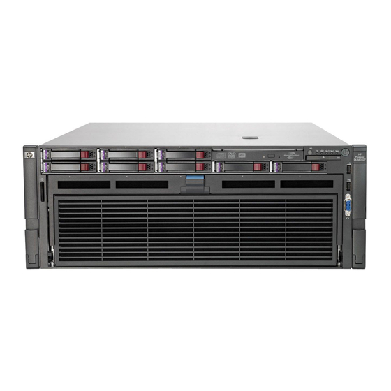
Page 7: Component Identification
Component identification Front panel components Item Description Serial and PID tag Optical drive Systems Insight Display USB connectors (2) Video connector Processor memory drawer Component identification 7... -
Page 8: Front Panel Leds And Buttons
Front panel LEDs and buttons Item Description Status UID button and LED Blue—Activated Blue (flashing)—Server being managed remotely Off—Deactivated Health LED Green—Normal (system on) Amber (flashing)—Internal system health degraded Red (flashing)—Internal system health critical Off—Normal (system off) NIC 1 LED Green—Linked to network Green (flashing)—Linked with activity on the network Off—No network connection... -
Page 9: Systems Insight Display
Systems Insight Display The Systems Insight Display LEDs represent the server and component layout. Description Off—No protection AMP status Green—Protection enabled Amber—Memory failure occurred Amber (flashing)—Memory configuration error Green—Normal (system on) Health Amber (flashing)—Internal system health degraded Red (flashing)—Internal system health critical Off—Normal (system off) Green—System on or requesting poweron Power cap... -
Page 10: Rear Panel Components
Rear panel components Item Description Item Description Power supply bay 4 (optional) Expansion slot 2 (optional) Power supply bay 3 (optional) Expansion slot 3 (optional) Power supply bay 2 Expansion slot 4 (optional) Power supply bay 1 Expansion slot 5 (optional) Mouse connector Expansion slot 6 (optional) Serial connector... -
Page 11: Rear Panel Leds And Buttons
Rear panel LEDs and buttons Item Description LED color Status iLO 3 NIC Activity LED Green On or flashing—Network activity Off—No network activity iLO 3 NIC Link LED Green On—Linked to network Off—Not linked to network NIC 2 Activity LED Green On or flashing—Network activity Off—No network activity... -
Page 12: Power Supply Led
Power supply LED Power LED Status No AC power to power supply units AC is present. Standby output is on, output is disabled. Green AC is present. Standby output is on, power supply DC output is on and Green Power supply failure (includes overvoltage and overtemperature) Component identification 12... -
Page 13: System Board Components
System board components Item Description Optional I/O expansion board connectors: • PCI-X/PCI Express I/O expansion board • PCI Express I/O expansion board Slot 7 PCIe2 x8 (8, 4, 2, 1) Slot 8 PCIe2 x8 (8, 4, 2, 1) Slot 9 PCIe2 x16 (16, 8, 4, 2, 1) Slot 10 PCIe2 x8 (8, 4, 2, 1) Slot 11 PCIe2 x16 (16, 8, 4, 2, 1) SPI board connector... -
Page 14: System Maintenance Switch
System maintenance switch The system maintenance switch (SW5) is an ten-position switch that is used for system configuration. The default position for all ten positions is Off. Position Description Function iLO 3 Security Off = iLO 3 security is enabled. On = iLO 3 security is disabled. -
Page 15: Spi Board Components
SPI board components Item Description Mini-SAS connectors (2) SAS cache connector TPM connector Fan data connector RMII connector SD card slot Battery 10Gb NIC connector* NIC cache connector* NIC 3 connector NIC 1 connector Video connector Keyboard connector USB connectors (2) iLO 3 connector Mouse connector Serial connector... -
Page 16: I/O Expansion Board Components
I/O expansion board components • PCI-X/PCI Express I/O expansion board Item Description Slot 6 PCIe2 x16 (16, 8, 4, 2, 1) Slot 5 PCIe2 x8 (8, 4, 2, 1) Slot 4 PCIe2 x8 (8, 4, 2, 1) Slot 3 PCIe2 x4 (4, 2, 1) Slot 2 PCI-X Slot 1 PCI-X •... -
Page 17: Dimm Slot Locations
Item Description Slot 2 PCIe2 x8 (8, 4, 2, 1) Slot 1 PCIe1 x8 (8, 4, 2, 1) DIMM slot locations • Primary processor memory board Component identification 17... -
Page 18: Device Numbers
• Secondary processor memory board Device numbers Component identification 18... -
Page 19: Sas Hard Drive Leds
SAS hard drive LEDs Item Description Fault/UID LED (amber/blue) Online LED (green) SAS hard drive LED combinations Online/activity Fault/UID LED Interpretation LED (green) (amber/blue) Alternating amber and The drive has failed, or a predictive failure alert has been On, off, or blue received for this drive;... -
Page 20: Battery Pack Leds
Online/activity Fault/UID LED Interpretation LED (green) (amber/blue) Steadily amber A critical fault condition has been identified for this drive, and the controller has placed it offline. Replace the drive as soon as possible. Amber, flashing A predictive failure alert has been received for this drive. Replace regularly (1 Hz) the drive as soon as possible. - Page 21 A fully-charged battery can normally preserve data for at least 2 days. The battery lifetime also depends on the cache module size. For more information, see the controller QuickSpecs on the HP website (http://www.hp.com). Double flash, then...
-
Page 22: Fbwc Module Leds
FBWC module LEDs The FBWC module has two single-color LEDs (green and amber). The LEDs are duplicated on the reverse side of the cache module to facilitate status viewing. 1 Green LED 2 Amber LED Interpretation A backup is in progress. A restore is in progress. -
Page 23: Fan Locations
Fan locations Power supply backplane components Component identification 23... - Page 24 Item Description Graphics card power connector Graphics card power connector Graphics card power connector SAS backplane power connector Fan power connector Component identification 24...
-
Page 25: Operations
Operations Power up the server To power up the server, press the Power On/Standby button. Power down the server WARNING: To reduce the risk of personal injury, electric shock, or damage to the equipment, remove the power cord to remove power from the server. The front panel Power On/Standby button does not completely shut off system power. -
Page 26: Remove The Access Panel
Extend the server on the rack rails until the server rail-release latches engage. After performing the installation or maintenance procedure, slide the server into the rack by pressing the server rail-release latches. Remove the access panel WARNING: To reduce the risk of personal injury from hot surfaces, allow the drives and the internal system components to cool before touching them. -
Page 27: Install The Access Panel
Extend the server from the rack (on page 25). Open the locking latch, slide the access panel to the rear of the chassis, and remove the access panel. If the locking latch is locked, use a T-15 Torx screwdriver to unlock the latch. Install the access panel Place the access panel on top of the server. -
Page 28: Access The Systems Insight Display
Firmly holding the processor memory drawer, press the release buttons and then remove the drawer from the server. Access the Systems Insight Display To access the Systems Insight Display: Press and release the panel. After the display fully ejects, rotate the display downward to view the LEDs. Remove the SPI board To remove the component: Power off the server. - Page 29 Remove the access panel (on page 26). Disconnect all cables from the SPI board. IMPORTANT: If replacing the SPI board or clearing NVRAM, you must re-enter the server serial number through RBSU ("Re-entering the server serial number and product ID" on page 76). Raise the levers, and lift the SPI board from the server.
-
Page 30: Setup
For more information on HP Care Pack Services, see the HP website (http://www.hp.com/services/carepack). Rack planning resources The rack resource kit ships with all HP branded or Compaq branded 9000, 10000, and H9 series racks. For more information on the content of each resource, see the rack resource kit documentation. Optimum environment When installing the server, select a location that meets the environmental standards described in this section. -
Page 31: Space And Airflow Requirements
HP servers draw in cool air through the front door and expel warm air through the rear door. Therefore, the front and rear rack doors must be adequately ventilated to allow ambient room air to enter the cabinet, and the rear door must be adequately ventilated to allow the warm air to escape from the cabinet. -
Page 32: Power Requirements
Because of the high ground-leakage currents associated with multiple servers connected to the same power source, HP recommends the use of a PDU that is either permanently wired to the building’s branch circuit or includes a nondetachable cord that is wired to an industrial-style plug. NEMA locking-style plugs or those complying with IEC 60309 are considered suitable for this purpose. -
Page 33: Identifying The Contents Of The Server Shipping Carton
WARNING: To reduce the risk of personal injury or damage to the equipment, be sure that: • The leveling jacks are extended to the floor. The full weight of the rack rests on the leveling jacks. • The stabilizing feet are attached to the rack if it is a single-rack installation. •... -
Page 34: Installing The Operating System
HP website (http://www.hp.com/support). Follow the on-screen instructions to begin the installation process. For information on using these installation paths, refer to the SmartStart installation poster in the HP ProLiant Essentials Foundation Pack, included with the server. Registering the server To register the server, refer to the HP Registration website (http://register.hp.com). -
Page 35: Hardware Options Installation
Hardware options installation Introduction If more than one option is being installed, read the installation instructions for all the hardware options and identify similar steps to streamline the installation process. WARNING: To reduce the risk of personal injury from hot surfaces, allow the drives and the internal system components to cool before touching them. - Page 36 Remove the tray with the I/O enabler board. CAUTION: When installing the tray with the secondary processor memory board, be sure that all DIMM latches on the primary processor memory board are in the fully-locked position. Failure to do so results in damage to the primary processor memory board. Install the tray with the secondary processor memory board.
-
Page 37: Processor Options
2 and the I/O enabler must be installed. To install the component: Update the system ROM. Locate and download the latest ROM version from the HP website (http://www.hp.com/support). Follow the instructions on the website to update the system ROM. Power down the server (on page 25). - Page 38 Remove the processor memory drawer cover. If not installed, install the secondary processor memory board ("Secondary processor memory board option" on page 35). Remove the processor socket protective cover. Hardware options installation 38...
- Page 39 Open the processor socket retaining bracket and the processor locking lever. IMPORTANT: Be sure the processor remains inside the processor installation tool. If the processor has separated from the installation tool, carefully re-insert the processor in the tool. Handle the processor by the edges only, and do not touch the bottom of the processor, especially the contact area.
- Page 40 The processor fits one way into the socket. Use the alignment guides on the processor and socket to properly align the processor with the socket. Install the spare processor. THE PINS ON THE SYSTEM BOARD ARE VERY FRAGILE AND EASILY DAMAGED. CAUTION: THE PINS ON THE SYSTEM BOARD ARE VERY FRAGILE AND EASILY DAMAGED.
- Page 41 Remove the thermal interface media protective cover. CAUTION: To avoid possible mechanical or thermal damage to the server, orient the heatsinks so that the alignment arrows and text are closest to the center of the server. Hardware options installation 41...
- Page 42 Align and install the heatsink. Alternate tightening the screws until the heatsink is seated properly. Repeat steps 8–13 for the other processor and heatsink. Remove the DIMM baffle from the secondary processor memory board. Install the DIMMs on the secondary processor memory board. Hardware options installation 42...
-
Page 43: Memory Configurations
For detailed DIMM population guidelines, see "Memory configurations (on page 43)." Install the DIMM baffle. Install the processor memory drawer cover. Install the processor memory drawer. Power up the server (on page 25). Memory configurations This server supports up to 1 TB of system memory using DDR3 2-GB, 4-GB, 8-GB, 16-GB, and 32-GB memory modules across 48 memory sockets. -
Page 44: Population Rules
Population rules When installing memory modules, observe the following population rules: • Use only HP memory modules listed in the DL585 QuickSpecs at the HP website (http://www.hp.com/servers/proliant). • Advanced ECC is not available if x4 and x8 memory modules are mixed in channels (A and B), (C and D), or both, but standard ECC is still available. -
Page 45: Memory Bus Speed
When Online Spare memory is enabled, one of the ranks is set aside as the Online spare rank. In the event that ranks of different sizes are on the same memory channel, a rank is selected that will be able to contain any of the ranks in the event of an Online spare switchover. -
Page 46: Single-, Dual-, And Quad-Rank Dimms
DR 1066 MHz — 3 mixed SR 1333 MHz 1066 MHz 800 MHz DR 1333 MHz DR 1066 MHz SR 1333 MHz 800 MHz 667 MHz DR 1333 MHz DR 1066 MHz QR 1066 MHz 800 MHz—The memory bus speed is set to 800 MHz regardless of the quantity of memory modules installed, unless the table above reflects a slower memory bus speed. -
Page 47: Advanced Ecc Memory
R = RDIMM (registered) E = UDIMM (unbuffered with ECC) For the latest supported memory information, see the QuickSpecs on the HP website (http://www.hp.com). Advanced ECC memory Advanced ECC memory is the memory protection mode for this server. In Advanced ECC, the server does not fail because of correctable memory errors. - Page 48 Remove the tray. Remove the DIMM baffle. Install the DIMMs. Hardware options installation 48...
-
Page 49: Installing Dimms On The Secondary Processor Memory Board
For configuration options, see "Memory configurations (on page 43)." Install the DIMM baffle. CAUTION: When installing the tray with the secondary processor memory board, be sure that all DIMM latches on the primary processor memory board are in the fully-locked position. Failure to do so results in damage to the primary processor memory board. -
Page 50: Hot-Plug Hard Drive Option
Remove the DIMM baffle. Install the DIMMs. For configuration options, see "Memory configurations (on page 43)." Install the DIMM baffle. Install the processor memory drawer cover. Install the processor memory drawer. Power up the server (on page 25). Hot-plug hard drive option When adding hard drives to the server, observe the following general guidelines: Hardware options installation 50... - Page 51 • The system automatically sets all device numbers. • If only one hard drive is used, install it in the bay with the lowest device number. • Hard drives must be SFF types. Drives should be the same capacity to provide the greatest storage space efficiency when drives are grouped together into the same drive array.
-
Page 52: Redundant Hot-Plug Power Supply Option
The server supports up to four hot-plug power supplies. Install all power supplies to provide full redundancy. HP recommends installing redundant hot-plug power supplies in pairs. To confirm the redundancy of your configuration, see the HP power advisor at the HP website (http://www.hp.com/go/hppoweradvisor). -
Page 53: Internal Solid State Drive Expansion Bay Option
Slide the power supply into the power supply bay until the device locks into place. Connect the power cord to the power supply. Connect the power cord to the power source. Be sure that the power supply LED is green ("Power supply LED"... -
Page 54: Expansion Board Options
The cable and the cable arrangement might appear differently from shown. Install the SPI board. Install the access panel (on page 27). Slide the server back into the rack. Power up the server (on page 25). Expansion board options The server supports up to 11 expansion slots. The server ships with 5 PCI Express expansion slots. To support the optional expansion slots, install one of the following options into the server: •... -
Page 55: Securing An Expansion Board For Shipping
Open the expansion board retainer, and then remove the expansion slot cover. Install the expansion board. If necessary, install the shipping screw. For more information, see "Securing an expansion board for shipping (on page 55)." Close the expansion slot retainer. Connect any required internal or external cables to the expansion board. - Page 56 CAUTION: To prevent improper cooling and thermal damage, do not operate the server unless all expansion slots have either an expansion slot cover or an expansion board installed. Power down the server (on page 25). Extend the server from the rack (on page 25). Remove the access panel (on page 26).
-
Page 57: Installing The Pci Express I/O Expansion Board
Install the shipping screw. Close the expansion slot retainer. Install the access panel (on page 27). Slide the server back into the rack. Power up the server (on page 25). Resume normal server operations. Installing the PCI Express I/O expansion board CAUTION: To prevent improper cooling and thermal damage, do not operate the server unless all expansion slots have either an expansion slot cover or an expansion board installed. - Page 58 Release the latches on the release lever. Lower the handle, and then extend the processor memory drawer from the server until the release latches catch. Hardware options installation 58...
-
Page 59: Installing The Pci-X/Pci Express I/O Expansion Board
Install the PCI Express I/O expansion board. Install any expansion boards ("Installing an expansion board" on page 54). Slide the processor memory drawer back into the server. Install the access panel (on page 27). Slide the server back into the rack. Power up the server (on page 25). - Page 60 Release the latches on the release lever. Lower the handle, and then extend the processor memory drawer from the server until the release latches catch. Hardware options installation 60...
-
Page 61: Hp Nc524Sfp Dual Port 10Gbe Module Option
When installed on the SPI board, the HP NC524SFP Dual Port 10GbE Module provides two 10G NIC connectors for server I/O. When the HP NC524SFP module is installed, 1G NIC connectors 1 and 2 on the rear panel are unavailable. - Page 62 Install the mini-DIMM on the SPI board. Install the SPI board. Using a T-15 Torx screwdriver, remove the 10G NIC adapter blank. Save the retaining screw. Install the HP NC524SFP module on the SPI board. Hardware options installation 62...
-
Page 63: Battery-Backed Write Cache Module
Connect the network cables. Power up the server (on page 25). Battery-backed write cache module The HP BBWC protects against hard boot, power, controller, and system board failures. The server supports the following battery-backed options: • 256-MB cache module (standard) •... - Page 64 The BBWC consists of two parts: a battery pack and a storage cache module. Along with the cache module, the battery pack provides transportable data protection, increases overall controller performance, and maintains any cached data for up to 72 hours after the server loses power. The NiMH batteries in the battery pack are continuously recharged through a trickle-charging process whenever the system power is on.
-
Page 65: Fbwc Module And Capacitor Pack Option
Attach the cable to the cache module. Install the battery. Connect the cable to the battery. The SPI board is not shown for clarity. Install the access panel (on page 27). Slide the server back into the rack. Power up the server (on page 25). FBWC module and capacitor pack option Hardware options installation 65... - Page 66 CAUTION: The cache module connector does not use the industry-standard DDR3 mini-DIMM pinout. Do not use the controller with cache modules designed for other controller models, because the controller can malfunction and you can lose data. Also, do not transfer this cache module to an unsupported controller model, because you can lose data.
-
Page 67: Hp Trusted Platform Module Option
Retaining the recovery key/password (on page 68). Enabling the Trusted Platform Module (on page 70). Enabling the TPM requires accessing RBSU ("HP ROM-Based Setup Utility" on page 72). For more information about RBSU, see the HP website (http://www.hp.com/go/ilomgmtengine/docs). Hardware options installation 67... -
Page 68: Retaining The Recovery Key/Password
Recovery Mode after BitLocker detects a possible compromise of system integrity. • HP is not liable for blocked data access caused by improper TPM use. For operating instructions, see the encryption technology feature documentation provided by the operating system. - Page 69 Extend the server from the rack (on page 25). Remove the SPI board (on page 28). Locate the TPM connector ("SPI board components" on page 15). CAUTION: Any attempt to remove an installed TPM from the system board breaks or disfigures the TPM security rivet.
-
Page 70: Enabling The Trusted Platform Module
OS application TPM settings. For more information on firmware updates and hardware procedures, see the HP Trusted Platform Module Best Practices White Paper on the HP website (http://www.hp.com/support). -
Page 71: Cabling
Cabling DVD-ROM drive cabling Cabling 71... -
Page 72: Server Software And Configuration Utilities
For more information, and to download the SmartStart Scripting Toolkit, see the HP website (http://www.hp.com/servers/sstoolkit). HP ROM-Based Setup Utility RBSU is a configuration utility embedded in HP ProLiant servers that performs a wide range of configuration activities that can include the following: •... -
Page 73: Using Rbsu
Selecting the primary boot controller • Configuring memory options • Language selection For more information on RBSU, see the HP ROM-Based Setup Utility User Guide on the Documentation CD or the HP website (http://www.hp.com/support/smartstart/documentation). Using RBSU To use RBSU, use the following keys: •... -
Page 74: Boot Options
RBSU by pressing the F9 key when prompted. After the settings are selected, exit RBSU and allow the server to reboot automatically. For more information on RBSU, see the HP ROM-Based Setup Utility User Guide on the Documentation CD or the HP website (http://www.hp.com/support/smartstart/documentation). -
Page 75: Array Configuration Utility
For Linux servers, see the README.TXT file for additional browser and support information. For more information about the controller and its features, see the HP Smart Array Controllers for HP ProLiant Servers User Guide on the HP website (http://www.hp.com/support/SAC_UG_ProLiantServers_en). To configure arrays, see the Configuring Arrays on HP Smart Array Controllers Reference Guide on the HP website (http://www.hp.com/support/CASAC_RG_en). -
Page 76: Re-Entering The Server Serial Number And Product Id
ASR is a feature that causes the system to restart when a catastrophic operating system error occurs, such as a blue screen, ABEND (does not apply to HP ProLiant DL980 Servers), or panic. A system fail-safe timer, the ASR timer, starts when the System Management driver, also known as the Health Driver, is loaded. When the... -
Page 77: Rompaq Utility
ASR increases server availability by restarting the server within a specified time after a system hang. At the same time, the HP SIM console notifies you by sending a message to a designated pager number that ASR has restarted the system. You can disable ASR from the System Management Homepage or through RBSU. -
Page 78: Redundant Rom Support
ROM. USB support HP provides both standard USB 2.0 support and legacy USB 2.0 support. Standard support is provided by the OS through the appropriate USB device drivers. Before the OS loads, HP provides support for USB devices through legacy USB support, which is enabled by default in the system ROM. -
Page 79: Diagnostic Tools
• From within the iLO 3 user interface • From within HP Insight Diagnostics (on page 79) For more information, see the Management CD or DVD in the HP Insight Foundation suite for ProLiant. Server software and configuration utilities 79... -
Page 80: Remote Support And Analysis Tools
If you are installing drivers from the SmartStart CD, be sure that you are using the latest SmartStart version that your server supports. To verify that your server is using the latest supported version, see the HP website (http://www.hp.com/support). For more information, see the documentation provided with the SmartStart If you do not use the SmartStart CD to install an OS, drivers for some of the new hardware are required. -
Page 81: Version Control
For example: http://www.hp.com/support/dl360g6 (http://www.hp.com/support/dl360g6) Version control The VCRM and VCA are Web-enabled Insight Management Agents tools that HP SIM uses to facilitate and schedule software update tasks to the entire enterprise. • VCRM manages the repository for Windows and Linux PSPs as well as online firmware. Administrators can browse a graphical view of the PSPs or configure VCRM to automatically update the repository with Internet downloads of the latest software from HP. -
Page 82: Change Control And Proactive Notification
Downloads the latest components from Web • Enables direct update of BMC firmware (iLO and LO100i) For more information about HP SUM and to access the HP Smart Update Manager User Guide, see the HP website (http://www.hp.com/go/hpsum/documentation). Change control and proactive notification HP offers Change Control and Proactive Notification to notify customers 30 to 60 days in advance of upcoming hardware and software changes on HP commercial products. -
Page 83: Troubleshooting
Troubleshooting Troubleshooting resources The HP ProLiant Servers Troubleshooting Guide provides procedures for resolving common problems and comprehensive courses of action for fault isolation and identification, error message interpretation, issue resolution, and software maintenance on ProLiant servers and server blades. This guide includes problem-specific flowcharts to help you navigate complex troubleshooting processes. -
Page 84: Symbols On Equipment
Warnings and cautions WARNING: Only authorized technicians trained by HP should attempt to repair this equipment. All troubleshooting and repair procedures are detailed to allow only subassembly/module-level repair. Because of the complexity of the individual boards and subassemblies, no one should attempt to make repairs at the component level or to make modifications to any printed wiring board. -
Page 85: Symptom Information
If the problem occurs randomly, what is the duration or frequency? To answer these questions, the following information may be useful: • Run HP Insight Diagnostics (on page 79) and use the survey page to view the current configuration or to compare it to previous configurations. •... -
Page 86: Loose Connections
(http://h18013.www1.hp.com/products/servers/management/agents/index.html ) and select Version Control Agent. The VCA gives you a list of names and versions of all installed HP drivers, Management Agents, and utilities, and whether they are up-to-date. HP recommends you have access to the server documentation for server-specific information. -
Page 87: Service Notifications
Troubleshoot a Problem link on the product page. Troubleshooting flowcharts To effectively troubleshoot a problem, HP recommends that you start with the first flowchart in this section, "Start diagnosis flowchart (on page 87)," and follow the appropriate diagnostic path. If the other flowcharts do not provide a troubleshooting solution, follow the diagnostic steps in "General diagnosis flowchart (on... -
Page 88: General Diagnosis Flowchart
Item "Symptom information (on page 85)" "Loose connections (on page 86)" "Service notifications (on page 87)" The most recent version of a particular server or option firmware is available on the HP Support website (http://www.hp.com/support). Troubleshooting 88... - Page 89 Item "General memory problems are occurring" in the HP ProLiant Servers Troubleshooting Guide located on the Documentation CD or see "Troubleshooting resources (on page 83)" Server maintenance and service guide, located on the Documentation CD or the HP website (http://www.hp.com/products/servers/platforms) •...
-
Page 90: Server Power-On Problems Flowchart
Server power-on problems flowchart Symptoms: • The server does not power on. • The system power LED is off or amber. Troubleshooting 90... - Page 91 Faulty internal component Item "Server health LEDs" and "Component identification (on page 7)" "HP Insight Diagnostics (on page 79)" or in the HP ProLiant Servers Troubleshooting Guide located on the Documentation CD or see "Troubleshooting resources (on page 83)" "Loose connections (on page 86)"...
- Page 92 Troubleshooting 92...
-
Page 93: Post Problems Flowchart
KVM or iLO 3 documentation "POST error messages and beep codes (on page 98)" "Symptom information (on page 85)" "Port 85 and iLO messages" in the HP ProLiant Servers Troubleshooting Guide located on the Documentation CD or see "Troubleshooting resources (on page 83)"... - Page 94 Troubleshooting Guide located on the Documentation CD or see "Troubleshooting resources (on page 83)" • "Operating system information you need" in the HP ProLiant Servers Troubleshooting Guide located on the Documentation CD or see "Troubleshooting resources (on page 83)" Troubleshooting 94...
-
Page 95: Os Boot Problems Flowchart
Guide located on the Documentation CD or see "Troubleshooting resources (on page 83)" • Controller documentation "HP Insight Diagnostics (on page 79)" or in the HP ProLiant Servers Troubleshooting Guide located on the Documentation CD or see "Troubleshooting resources (on page 83)" •... -
Page 96: Server Fault Indications Flowchart
Server fault indications flowchart Symptoms: • Server boots, but a fault event is reported by Insight Management Agents • Server boots, but the internal health LED, external health LED, or component health LED is red or amber NOTE: For the location of server LEDs and information on their statuses, refer to the server documentation. - Page 97 "Power-on problems flowchart ("Server power-on problems flowchart" on page 90)" "HP Insight Diagnostics (on page 79)" or in the HP ProLiant Servers Troubleshooting Guide located on the Documentation CD or see "Troubleshooting resources (on page 83)" • "Hardware problems" in the HP ProLiant Servers Troubleshooting Guide located on the Documentation CD or see "Troubleshooting...
-
Page 98: Post Error Messages And Beep Codes
POST error messages and beep codes For a complete listing of error messages, refer to the "POST error messages" in the HP ProLiant Servers Troubleshooting Guide located on the Documentation CD or on the HP website (http://www.hp.com/support). Troubleshooting 98... - Page 99 WARNING: To avoid potential problems, ALWAYS read the warnings and cautionary information in the server documentation before removing, replacing, reseating, or modifying system components. Troubleshooting 99...
-
Page 100: Battery Replacement
Battery replacement If the server no longer automatically displays the correct date and time, you may need to replace the battery that provides power to the real-time clock. WARNING: The computer contains an internal lithium manganese dioxide, a vanadium pentoxide, or an alkaline battery pack. A risk of fire and burns exists if the battery pack is not properly handled. -
Page 101: Regulatory Compliance Notices
Regulatory compliance notices Regulatory compliance identification numbers For the purpose of regulatory compliance certifications and identification, this product has been assigned a unique regulatory model number. The regulatory model number can be found on the product nameplate label, along with all required approval markings and information. When requesting compliance information for this product, always refer to this regulatory model number. -
Page 102: Declaration Of Conformity For Products Marked With The Fcc Logo, United States Only
Hewlett-Packard Company P. O. Box 692000, Mail Stop 530113 Houston, Texas 77269-2000 • 1-800-HP-INVENT (1-800-474-6836). (For continuous quality improvement, calls may be recorded or monitored.) For questions regarding this FCC declaration, contact us by mail or telephone: • Hewlett-Packard Company P. -
Page 103: European Union Regulatory Notice
Compliance with these directives implies conformity to applicable harmonized European standards (European Norms) that are listed in the EU Declaration of Conformity issued by HP for this product or product family and available (in English only) either within the product documentation or at the following HP website (http://www.hp.eu/certificates) (type the product number in the search field). -
Page 104: Japanese Notice
This symbol on the product or on its packaging indicates that this product must not be disposed of with your other household waste. Instead, it is your responsibility to dispose of your waste equipment by handing it over to a designated collection point for the recycling of waste electrical and electronic equipment. -
Page 105: Chinese Notice
Do not operate controls, make adjustments, or perform procedures to the laser device other than those specified herein. Allow only HP Authorized Service technicians to repair the unit. • The Center for Devices and Radiological Health (CDRH) of the U.S. Food and Drug Administration implemented regulations for laser products on August 2, 1976. -
Page 106: Taiwan Battery Recycling Notice
To forward them to recycling or proper disposal, use the public collection system or return them to HP, an authorized HP Partner, or their agents. For more information about battery replacement or proper disposal, contact an authorized reseller or an authorized service provider. -
Page 107: Brazilian Notices
WARNING: Exposure to Radio Frequency Radiation—The radiated output power of this device is below the FCC radio frequency exposure limits. Nevertheless, human contact during normal operation should be minimized. Brazilian notices Este equipamento opera em caráter secundário, isto é, não tem direito a proteção contra interferência prejudicial, mesmo de estações do mesmo tipo, e não pode causar interferência a sistemas operando em caráter primário. -
Page 108: Taiwan Notices
Taiwan notices Regulatory compliance notices 108... -
Page 109: Electrostatic Discharge
Electrostatic discharge Preventing electrostatic discharge To prevent damaging the system, be aware of the precautions you need to follow when setting up the system or handling parts. A discharge of static electricity from a finger or other conductor may damage system boards or other static-sensitive devices. -
Page 110: Specifications
Specifications Environmental specifications Specification Value Temperature range* 10°C to 35°C (50°F to 95°F) Operating -40°C to 70°C (-40°F to 158°F) Shipping 28°C (82.4°F) Maximum wet bulb temperature Relative humidity (noncondensing)** 10% to 90% Operating 5% to 95% Nonoperating * All temperature ratings shown are for sea level. An altitude derating of 1°C per 300 m (1.8°F per 1,000 ft) to 3,048 m (10,000 ft) is applicable. -
Page 111: Support And Other Resources
Active Health System log (HP ProLiant Gen8 or later products) Download and have available an Active Health System log for 3 days before the failure was detected. For more information, see the HP iLO 4 User Guide or HP Intelligent Provisioning User Guide on the HP website (http://www.hp.com/go/ilo/docs). - Page 112 HP specifies in the materials shipped with a replacement CSR part whether a defective part must be returned to HP. In cases where it is required to return the defective part to HP, you must ship the defective part back to HP within a defined period of time, normally five (5) business days. The defective part must be returned with the associated documentation in the provided shipping material.
- Page 113 HP sono realizzati con numerosi componenti che possono essere riparati direttamente dal cliente (CSR, Customer Self Repair). Se in fase di diagnostica HP (o un centro di servizi o di assistenza HP) identifica il guasto come riparabile mediante un ricambio CSR, HP lo spedirà direttamente al cliente per la sostituzione.
- Page 114 Si, durante la fase de diagnóstico, HP (o los proveedores o socios de servicio de HP) identifica que una reparación puede llevarse a cabo mediante el uso de un componente CSR, HP le enviará dicho componente directamente para que realice su sustitución. Los componentes CSR se clasifican en dos categorías:...
- Page 115 HP se hará cargo de todos los gastos de envío y devolución de componentes y escogerá la empresa de transporte que se utilice para dicho servicio. Para obtener más información acerca del programa de Reparaciones del propio cliente de HP, póngase en contacto con su proveedor de servicios local.
- Page 116 Opcional – Peças cujo reparo feito pelo cliente é opcional. Essas peças também são projetadas para o reparo feito pelo cliente. No entanto, se desejar que a HP as substitua, pode haver ou não a cobrança de taxa adicional, dependendo do tipo de serviço de garantia destinado ao produto.
- Page 117 Support and other resources 117...
- Page 118 Support and other resources 118...
-
Page 119: Acronyms And Abbreviations
Acronyms and abbreviations ABEND abnormal end Array Configuration Utility Array Diagnostics Utility Advanced Memory Protection Automatic Server Recovery BBWC battery-backed write cache Canadian Standards Association electrostatic discharge FBWC flash-backed write cache International Electrotechnical Commission iLO 3 Integrated Lights-Out 3 Integrated Management Log Acronyms and abbreviations 119... - Page 120 Option ROM Configuration for Arrays PCIe peripheral component interconnect express PCI-X peripheral component interconnect extended power distribution unit port ID POST Power-On Self Test HP ProLiant Support Pack RBSU ROM-Based Setup Utility serial attached SCSI Secure Digital small form factor Acronyms and abbreviations 120...
- Page 121 Systems Insight Manager system peripheral interface TMRA recommended ambient operating temperature Trusted Platform Module unit identification uninterruptible power system universal serial bus Version Control Agent Acronyms and abbreviations 121...
-
Page 122: Documentation Feedback
Documentation feedback HP is committed to providing documentation that meets your needs. To help us improve the documentation, send any errors, suggestions, or comments to Documentation Feedback (mailto:docsfeedback@hp.com). Include the document title and part number, version number, or the URL when submitting your feedback. -
Page 123: Index
73 connector, USB 7, 10, 15 Automatic Server Recovery (ASR) 76 connector, video 7, 10, 15 contacting HP 111 CSR (customer self repair) 111 Basic Input/Output System (BIOS) 74, 77, 88 customer self repair (CSR) 111 battery 15, 100... - Page 124 111 loose connections 86 HP Insight Diagnostics 79 HP Insight Remote Support software 80 HP NC524SFP Dual Port 10GbE Module 61 management tools 76 HP ProLiant Essentials Foundation Pack 34 memory 46, 47 HP Smart Update Manager overview 81...
- Page 125 processor option 37 mouse connector 10, 15 processors 37 ProLiant Support Pack (PSP) 81 PSP (ProLiant Support Pack) 81 NIC adapter blank 10 PSPs, overview 81 NIC connectors 10, 15 NVRAM, clearing 14 rack installation 30, 32, 33 rack mounting hardware 33 online spare memory 44, 74 rack resources 30 online spare population guidelines 44...
- Page 126 109 video connector 7, 10, 13, 15 status lights, battery pack 20 support 80, 111 support packs 72 website, HP 111 supported operating systems 81 wireless devices 106, 107, 108 symbols on equipment 84 symptom information 85 system battery 15...
Need help?
Do you have a question about the ProLiant DL585 G7 and is the answer not in the manual?
Questions and answers