Table of Contents
Advertisement
Advertisement
Table of Contents

Related Manuals for Furuno FS-1562-15


Summary of Contents for Furuno FS-1562-15
- Page 2 9 - 5 2 , A s h i h a r a - c h o , N i s h i n o m i y a , J a p a n T e l e p h o n e : 0 7 9 8 - 6 5 - 2111 T e l e f a x : 0 7 9 8 - 6 5 - 4 2 0 0...
-
Page 3: Safety Instructions
If you have any questions regarding these safety instructions, please contact a FURUNO agent or dealer. The level of risk appearing in the notices is defined as follows:... - Page 4 DANGER Do not work inside the equip- ment unless totally familiar with electrical circuits. Hazardous voltage which will cause death or serious injury exists at the following locations: • Transceiver unit • Antenna and antenna coupler (both at TX) HAZARDOUS VOLTAGE is present at these points.
-
Page 5: Table Of Contents
LIST OF CONTENTS INTRODUCTION ... iv Specifications of MF/HF Radiotelephone model FS-1562 ... v Chapter 1 OPERATION ... 1.1 SYSTEM SET-UP ... 1.1 Front View of Transceiver Unit ... 1.2 Power Supply Unit ... 1.4 Starting operation ... 1.5 Selecting Frequency ... 1.5 Transmitting ... -
Page 6: Introduction
In addition, TX/RX frequencies can be preprogrammed into a E 200 frequency pairs. There are two types of the FS-1562: FS-1562-15 (150 Wpep) and FS-1562-25 (250 Wpep), where pep is peak envelope power, the unit for addressing an output power in a Single Sideband (SSB) transmitter. -
Page 7: Specifications Of Mf/Hf Radiotelephone Model Fs-1562
Specifications of MF/HF Radiotelephone model FS-1562 The model FS-1562-15/25 complies with the following rules and regulations: IMO A.421(XI), A.610(15), A613(15), A.694(17) International Convention on Safety of Life at Sea 1974, as amended 1988 (GMDSS Conference) ITU Radio Regulations ETS 300 373... -
Page 8: Compass Safe Distance
0.4 m 0.9 m 0.7 m 0.9 m 0.7 m 1.0 m 0.7 m + 250 pF NOTE Furuno recommendation based on the ISO R 694 Method A tests for the variant models, added with correction factors which Furuno considers adequate. -
Page 9: Chapter 1 Operation
Antenna Coupler, and a Handset. Shown below are the system setup for 150 W and 250 W with DSC (Digital Selective Calling) terminal and other ancillaries. Antenna Coupler AT-1560-15 Transceiver Unit Telephone Handset SSB TRANSCEIVE FS-1562-15 SIMP 0 2 4 6 8 10 S External VOLUME RF GAIN Speaker... -
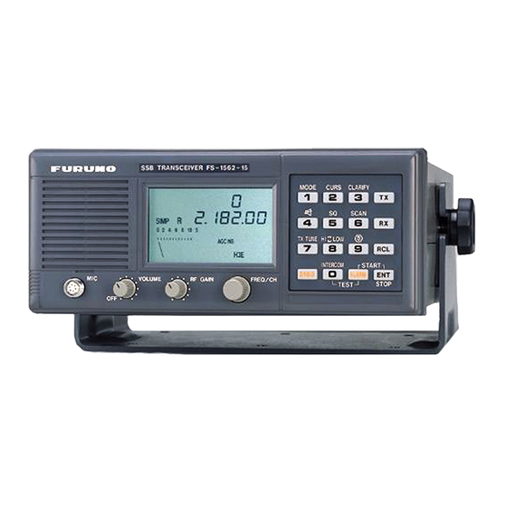
Page 10: Front View Of Transceiver Unit
1.2 Front View of Transceiver Unit (Same for FS-1562-15 and FS-1562-25) Loudspeaker Microphone Volume control Hndset Jack w/Power ON/OFF Rotary controls VOLUME Turns the power on and off and adjust the loudspeaker volume. When FS-1562 is connected to DB-500 and RB-500, FS-1562 can be turned on by RB-500. -
Page 12: Power Supply Unit
Supply Unit on AC mains supply (115 or 230 VAC). The power supply unit is type PR-300 supplying 24 VDC power (20 A) to the FS-1562-15 (150 W) Transceiver Unit or type PR-850A, supplying 24 VDC (40 A) for the FS-1562-25 (250 W). Both 115/230 VAC and 24 VDC power can be connected simultaneously. -
Page 13: Starting Operation
H3E AGC ON TLX AGC OFF Class of Emission Single Sideband radiotelephony Equivalent to AM radiotelephony. Radio Telex Reception of weather facsimile broadcast (*available with system setting by Furuno authorized service agent) -1.5- H3E AGC OFF TLX AGC ON... - Page 14 Designated by the CENTER frequencies TX Freq Standard type selection Free selection ITU Channels Custom Channels Preset by Furuno authorized service agent User countries - CEPT countries Netherlands type YES (Marine band only) indicated by frequency All channels in the APPENDIX...
-
Page 15: Direct Frequency Entry
Direct frequency entry Free selection is possible in Dutch Version (in marine bands only). To set for a receive frequency of 1636.4 kHz, for example; Press [RX], [1], [6], [3], [6], [4], [ENT] in this order. The decimal point is not required to enter. To set for a transmit frequency of 2061.4 kHz, for example;... -
Page 16: Custom Channels
Once a channel is selected with the keyboard, the channel can be changed with the FREQ/CH rotary selector. NOTE: Custom channel programming should be done by a FURUNO service agent. To call the channel 120, for example:... - Page 17 • The [CURS (cursor)] key shifts the cursor to band or channel number. • To change the channel number, you can use the rotary control. The [FREQ/CH] control changes the number above the cursor, a band or channel designator. ITU TELEX channels To select the ITU TELEX channel 4012, for example, first select TLX with the [MODE] key.
-
Page 18: Transmitting
1.6 Transmitting After selecting class of emission and frequency, you can transmit by pressing the PTT (press-to-talk) switch on the handset or microphone. Output power can be evaluated on the operation display. Tuning the antenna: Maximum transmission power is achieved only when the antenna impedance and transmitter impedance match each other. -
Page 19: Reducing Transmitter Power
“LOW” appears on the display when low output power is selected. Low power is 60 Wpep for FS-1562-15 and FS-1562-25, both. The output power on 2182 kHz (Distress and calling) and 2187.5 kHz (DSC) is the rated maximum regardless of the position of the [HI/LOW] switch. -
Page 20: Distress Frequencies
2. Distress calls and Distress message Speak slowly and distinctly, “MAYDAY, MAYDAY, MAYDAY, pronounced as the French expression “m’aider”. This is; The name of your vessel and call sign three times. Then, continue with the distress message, which consists of: The distress signal MAYDAY;... -
Page 21: In The Event Of Antenna Coupler Failure
When connected to a DSC Terminal without remote control: 1. Select 2187.5 kHz on the FS-1562. (This step is not required with Furuno DSC-6.) 2. Press the [DISTRESS] key on the DSC Terminal. The DSC distress signal is transmitted over 2187.5 kHz. -
Page 22: Receiving
3. To terminate this operation, press the [3] CLARIFY key again. The cursor returns to the channel number. NOTE: The clarify working range can be adjusted, by an authorized FURUNO representative, 100 Hz or 150 Hz (factory setting: the range on AM is fixed at 5 kHz (100 Hz steps). -
Page 23: Frequency Scan
Squelch control: Squelch is used to mute the receiver audio output when the receiver input is less than a preset value or dominant noise is higher than a preset (1000 Hz) level. To switch the squelch function ON, press the [5] SQUELCH key. Make sure the label “SQ” appears on the display. To pick up a weak signal at high audio frequencies, you should remove the squelch function notwithstanding a possible increase of background noise. -
Page 24: Frequency Sweep
ITU channels: To select the scan group (band or channel), shift the cursor to either the position of the band or channel number by pressing the [2] CURS key. (Band scan is useful to watch frequencies on the same channel in different bands.) 2. -
Page 25: Operation Of Optional Devices
2.1 Telex Communication Telex communication is performed with a Narrow-band direct-printing (NBDP) Terminal connected with an SSB transceiver. The recommended terminal for the FS-1562 is FURUNO DP-6. Other makes can also be connected with the FS-1562, if they comply with the interfacing requirements. -
Page 26: Intercom
2.2 Intercom The intercom provides communications between the FS-1562 and the RB-500 Remote Station (option). They must be wire-connected. When intercom mode is in use, there is no radio transmission. Calling RB-500 1. Press the [0] INTERCOM key. “COM” appears on the FS-1562 display panel. 2. -
Page 27: Chapter 3 Changing System Setting
Chapter 3 3.1 SYSTEM SETUP 1. While pressing and holding down the [RCL] key, turn on the power. Release the [RCL] key when the “MEMO” appears on the display. MEMO 2. Turn the FREQ/CH control to select a desired code number. 3. - Page 28 9951 Scan/sweep-stop signal level When the receiver detects a signal whose level is stronger than the preset level it stops scanning and receives the signal. The setting on system code 9955 is available only when “0” (SQ working condition) is selected here. Setting range: 0 (Squelch working condition is effective as set on code 9995), 1-10 (S-meter level);...
- Page 29 1300 Hz as the squelch opens at that frequency.) 9999 This is for frequency programming by service technicians. Needs a password to open. NOTE: FURUNO Electric Company will assume no responsibility for the inconvenience or disturbance to communications due to inadequate or unlawful presetting of this equipment. -3.3-...
- Page 30 This page is intentionally left blank.
-
Page 31: Chapter 4 Maintenance
Chapter 4 4.1 Weekly Checks Check the radiotelephone at appropriate intervals as required by Administration. For instance, Japanese Administration requires check of DSC every day. US 47 CFR 47, PART 80.869-Test of radiotelephone station calls for: Unless the normal use of the required radiotelephone station demonstrates that the equipment is operating, a test communication on a required or working frequency must be made each day the ship is navigated. - Page 32 If a fault is detected, “no Good” appears instead of “Good” and the associated indication blinks after completion of this test. Turn off the transceiver on completion of tests. Turn on again for normal operation. Receiver section tested successfully. Transmitter Exciter stage is tested successfully. Transmitter Power Amplifier stage and Antenna Coupler (Coupler and Dummy Board) are tested successfully.
-
Page 33: Lcd/Keyboard Test & Rom Version No. Confirmation
4.3 LCD/Keyboard Test & ROM Version No. Confirmation 1. While pressing and holding down the [ENT] key, turn on the power. All LCD segments appear. 2. Release the [ENT] key. 3. Press keys one by one. Check if the indication on the operation display is correct as shown below: Indication Indication... -
Page 34: Antenna Coupler Test
4.4 Antenna Coupler Test The CPU and the relays which select capacitors and coils for tuning can be checked. For Competent technicians only DANGER HIGH VOLTAGE Still alive at OFF DANGER - Electrical Shock Hazard Discharge before servicing Procedure 1. Open the antenna coupler cover. 2. -
Page 35: Maintenance
4.5 Maintenance This radiotelephone equipment is designed and manufactured to provide years of intended performance. For this, a regular maintenance program should be established and should at least include the items listed in below: Item Whip antenna Check for physical damage, corrosion and water leakage Wire antenna Check that antenna is properly spanned... - Page 36 Item Power cable Check for loosened or corroded connection at power terminals. Battery Check that the battery is fully charged. Feeder (coax Check for physical damage. cable, control cable) PCB connection Check that jumper cables between boards are firmly connected. Microphone Check that jumper cables between boards are firmly connected.
-
Page 37: Chapter 5 Troubleshooting
Chapter 5 5.1 Troubleshooting List For qualified personnel only The troubleshooting list below gives common symptoms of equipment malfunction and means to restore normal operation. If you cannot restore normal operation, please do not check inside any unit. Any repair is best left to a qualified radiotelephone technician. Improper handling or adjustment may cause more serious damage. - Page 38 TROUBLE Key input is not accepted Antenna coupler can’t tune antenna Can not tune in a broadcast station PROBABLE CAUSE FS-1562 is under control of external equipment Antenna may be disconnected or shorted to ground Antenna is out of tunable length. Poor grounding of the coupler.
-
Page 39: Error Indication
5.2 Error Indication When the FS-1562 detects a fault in the synthesizer unit (frequency unlocked), the frequency or channel number blinks. 5.3 Replacing Fuses To protect the unit from overcurrent and equipment fault, two 20 A fuses for the transceiver unit (and two 30 A fuses for the PA-2500) are provided in snap-in holders on the power cable and two fuses in the PR-300 Power Supply Unit (for 150 W set). - Page 40 This page is intentionally left blank.
-
Page 41: Appendix
APPENDIX CUSTOM CHANNELS/FREQUENCIES - To be programmed by Furuno Dealers CH NO Ship Receive (kHz) Ship Transmit (kHz) Remarks -AP.1-... - Page 42 2126.0 2206.0 2382.0 2430.0 Above is not factory programmed, should be programmed by Furuno representatives. Unlimited use December 15 to April 1 Limited to pep of 150 W. NOTE: indicate the outline only. Refer to the relative documentation for full detail. For other coast stations, consult with your dealers.
- Page 43 MF band SSB working carrier frequencies Ship Receive CH NO (kHz) 1635 1638 1641 1644 1647 1650 1653 1656 1659 1662 1665 1668 1671 1674 1677 1680 1683 1686 1689 1692 1695 1698 1701 1704 1707 1710 1713 1716 1719 1722 Above is factory programmed.
- Page 44 4354 4146 4149 4000 4003 4006 4009 4012 4015 4018 CH NOs in ( ) are ITU NOs (RR Section C-1). 4021 Use 3-digit Furuno’s designators for selection. 4024 4027 4030 4033 4036 4039 4042 4045 4048 4051 4054 4057 4060 -AP.4-...
- Page 45 8 MHz ITU SSB carrier frequencies (ITU RR APPENDIX 16) The following frequencies are factory programmed. -AP.5- i t c i t c...
- Page 46 12/16 MHz ITU SSB carrier frequencies (ITU RR APPENDIX 16) 12 MHz SSB (J3E) CH NO. SHIP RX SHIP TX 1201 13077 12230 1202 13080 12233 1203 13083 12236 1204 13086 12239 1205 13089 12242 1206 13092 12245 1207 13095 12248 1208 13098...
- Page 47 18/19, 22, 25/26 MHz ITU SSB carrier frequencies (ITU RR APPENDIX 16) The following frequencies are factory programmed. 18/19 MHz SSB (J3E) CH NO. SHIP RX SHIP TX 1801 19755 18780 1802 19758 18783 1803 19761 18786 1804 19764 18789 1805 19767 18792...
-
Page 48: Telex Channels
TELEX CHANNELS MF BAND Telex FREQUENCY TABLE The following frequencies are factory programmed. A channel can be recalled by hitting the keys [RCL], [2], [0], [1], [ENT] for channel 201 as an example. Transmit and receive frequencies appear on the display. The channel number is checked by pressing the [ENT] key or by turning the FREQ/CH selector;... - Page 49 4/6 MHz BAND ITU NBDP (Telex) FREQUENCY TABLE (ITU RR APPENDIX 32) 4 MHz TELEX CH NO. SHIP RX SHIP TX 4001 4210.5 4172.5 4002 4211.0 4173.0 4003 4211.5 4173.5 4004 4212.0 4174.0 4005 4212.5 4174.5 4006 4213.0 4175.0 4007 4213.5 4175.5 4008...
- Page 50 8 MHz BAND ITU NBDP (Telex) FREQUENCY TABLE (ITU RR APPENDIX 32) 8 MHz TELEX CH NO. SHIP RX SHIP TX 8001 8376.5 8376.5 8002 8417 8377 8003 8417.5 8377.5 8004 8418 8378 8005 8418.5 8378.5 8006 8419 8379 8007 8419.5 8379.5 8008...
- Page 51 12 MHz BAND ITU NBDP (Telex) FREQUENCY TABLE The following frequencies are factory programmed. 12 MHz TELEX CH NO. SHIP RX SHIP TX 12001 12579.5 12477.0 12002 12580.0 12477.5 12003 12580.5 12478.0 12004 12581.0 12478.5 12005 12581.5 12479.0 12006 12582.0 12479.5 12007 12582.5...
- Page 52 12/16 MHz BAND ITU NBDP (Telex) FREQUENCY TABLE The following frequencies are factory programmed. -AP.12-...
- Page 53 16 MHz BAND ITU NBDP (Telex) FREQUENCY TABLE The following frequencies are factory programmed. -AP.13-...
- Page 54 18/19 MHz BAND ITU NBDP (Telex) FREQUENCY TABLE The following frequencies are factory programmed. -AP.14-...
- Page 55 22 MHz BAND ITU NBDP (Telex) FREQUENCY TABLE The following frequencies are factory programmed. 22 MHz TELEX CH NO. SHIP RX SHIP TX 22001 22376.5 22284.5 22002 22377.0 22285.0 22003 22377.5 22285.5 22004 22378.0 22286.0 22005 22378.5 22286.5 22006 22379.0 22287.0 22007 22379.5...
- Page 56 22, 25/26 MHz BAND ITU NBDP (Telex) FREQUENCY TABLE The following frequencies are factory programmed. -AP.16-...
Need help?
Do you have a question about the FS-1562-15 and is the answer not in the manual?
Questions and answers