Table of Contents
Advertisement
Advertisement
Table of Contents

Related Manuals for Swisher Z-max ZT2760


Summary of Contents for Swisher Z-max ZT2760
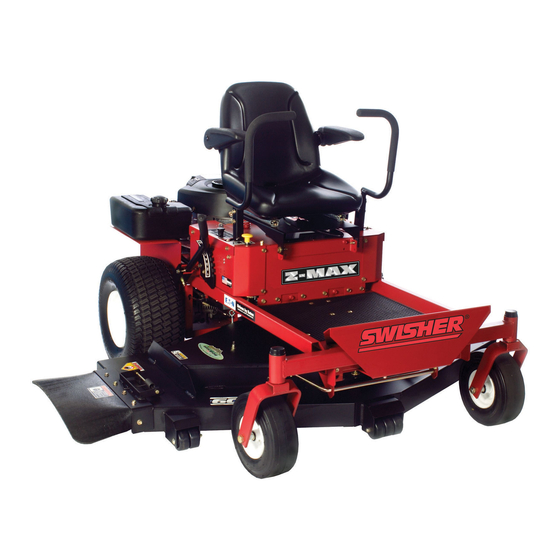
- Page 1 27 HP- 60" CUT CELEBRATING OVER 60 YEARS O FINNOVATION 1945- 2008 1602 CORPORATE DRIVE, P.O. BOX 67, WARRENSBURG, MISSOURI 64093 Made In The | PHONE 660-747-8183 FAX 660-747-8650 Manufacturing quality lawn care equipment since 1945 OWNER'S MANUAL 14700 STARTING SERIAL # TN108-01601 Rev.
- Page 2 Swisher Mower Co., Inc. or its agents responsible for the engine warranty. The Briggs & Stratton Engine Service Hot-Line is 1-800-233-3723.
- Page 4 INTRODUCTION Congratulations Thank you for purchasing a Swisher Zero Turn mower. This machine is built for the greatest efficiency and rapid mowing of large areas. Conveniently located controls and dual commercial grade hydrostatic transmissions regulated by steering levers, contribute to the machine's performance.
- Page 5 INTRODUCTION Uncrating & Assembly TOOLS REQUIRED: 2 - ½" Wrenches or ½" Socket with drive ratchet Tire pressure gauge Nail bar or claw hammer Wire snips To Remove The Mower From The Crate: Dispose of top and side panels of the crate. Remove loose parts and packing material.
- Page 6 SYMBOLS & DECALS OD45- Warning Decal Swisher Flag U.S.A.- OD39 Notice Do Not Alter Wiring Decal- OD74 Operator Must Be Seated Decal- OD73 Flying Debris Decal - OD43 Step Decal - OD 11 Triangle Danger Decal - OD55 TOFREE-WHEEL: PULL RODS OUT ON...
- Page 7 SAFETY INSTRUCTIONS These instructions are for your safety. Read them carefully. This Safety Alert Symbol indicates important messages in this manual. When you see this symbol, carefully read the message that follows and be alert to the possibility of personal injury. General Use Read all instructions in this operator's manual and on the machine before starting it.
- Page 8 SAFETY INSTRUCTIONS General Use Continued... ;* Always wear approved protective glasses or a full visor when assembling or driving. Ear Protection is recommended Remember ;* Never wear loose clothing that can get caught in moving parts. The operator is responsible avoiding dangers or accidents.
- Page 9 MOWING SAFETY •WARNING - Petrol is highly flammable. - store fuel in containers specifically designed for this purpose; - refuel outdoors only and do not smoke while refueling; - add fuel before starting the engine. Never remove the cap of the fuel tank or add petrol while the engine is running or when the engine is hot.
- Page 10 CUSTOMER RESPONSIBILITIES Operator Presence System Be sure the operator presence and interlock systems are working properly. If your mower does not function as described, repair the problem immediately. The engine should not start unless the parking brake is engaged and the PTO (Blade Engagement - See OPERATION FEATURES section of this manual) switch is disengaged (pressed down).
- Page 11 CUSTOMER RESPONSIBILITIES/SPECIFICATIONS V-Belts Check V-belts for deterioration and wear after 100 hours of operation and replace if necessary. Replace belts if they begin to slip from wear. SEE SPECIFICATION for belt part numbers and SERVICE section of this manual for instructions on how to replace the belt.
- Page 12 CUSTOMER RESPONSIBILITIES MAINTENANCE SCHEDULE Before Before Each 8 Hours 25 Hours 50 Hours 100 Hours Season Storage Check Brake Operation Check Tire Pressure Check Operator Presence Parking Brake Check for Loose Fasteners Sharpen/Replace Mower Blades Check Battery Clean Battery & Terminals Check Belts Check...
-
Page 13: Features & View
OPERATION FEATURES Throttle Control- Used to control Control Lever - Sets the speed of the mower in both the forward and reverse Engine Speed directions and also turns the mower. Hour Meter- Indicates hours of operation Hydro Bypass - Engages transmissions normal operation and disengages... - Page 14 OPERATION FEATURES _, _ i!_iii_i_i Throttle Control- Used to control Control Levers - Sets the speed of the mower in both the forward and reverse Engine Speed directions and also turns the mower. Hour Meter- Indicates hours of operation Hydro Bypass - Engages transmissions normal operation...
- Page 15 OPERATION FEATURES Left Control Panel Right Control Panel Rear of Unit Throttle Control- Used to control Control Levers - Sets the speed of the mower in both the forward and reverse Engine Speed directions and also turns the mower. Hour Meter- Indicates hours of operation...
- Page 16 OPERATION Starting Operator must be sitting in the seat. Control handles must be in the neutral (outward) position. PTO must be in the disengage position (pushed down). Set choke (if needed), turn key and release as soon as engine starts. Adjust throttle to half and shut choke off.
- Page 17 OPERATION Controls Be familiar with all controls, their functions and how to operate them before starting the machine. :_Motion control levers on each side of the console control the direction of movement. SEE FIGURE BELOW Control Handles Neutral Position Slow Forward Fast Forward Slow Reverse 90 Degree...
- Page 18 Lift deck using the deck lift handle to the desired position Parkinq Brakes ,/The Swisher ZT2760 is equipped with An Automatic Parking Brake system on each control handle. ,/When the control handles are in the out most position the parking brakes are on.
- Page 19 SERVICE & ADJUSTMENTS Deck Belt Routing & Replacement Removal Replacement ,/Disconnect spark plug wire ,/Install new belt by placing it around the deck pulleys. Refer to routing ,/Apply parking brake diagram below. ,/Lower the deck to its lowest position ,/The belt will be loose at this time ,/Remove the belt covers...
- Page 20 SERVICE & ADJUSTMENTS Hydro Belt Routing & Replacement Removal Replacement ,/Disconnect spark plug wire ,/Install new belt by placing it around the engine pulley and the hydro ,/Apply parking brake pulleys. Refer to routing diagram below. ,/Disconnect wiring from electric clutch ,/The belt will be loose at this time ,/Remove...
- Page 21 Reduction Adjustment (Ref. Page 21) ,/To improve the tracking of the Swisher ZT2760 the speed of one of the rear wheels needs to be decreased. If the ZT2760 pulls to the right the left wheel will need to decrease speed and if pulling to the left the right wheel will need to decrease speed.
- Page 22 WIRING HARNESS +i+Plm+H WARNING When it is necessary to raise the mower for any repair or service, use jackstands provide adequate support. DO NOT rely on hydraulic or mechanical jacks...
- Page 23 PARTS BREAKDOWN DETAIL D Item# Description Part# Item # Description Part # SCALE 1 +3 Screw- 1/4-14X.38" ST 26X229 Spring- Deck L ift H andle 10535 Solenoid- 3 Pole 1002004 Bolt- 5 /16-18 X3GR2 Z Y NB563 Bolt- SerfFlange,5t16-18X1GR5 ZY 10548 Handle- Height Adjust Weldment 9952 Linkage-Steering' 9"X 1.25"...
-
Page 24: Gas Tank Assembly
PARTS BREAKDOWN Item # Part# Description 12935 26 HP B&S Engine NB170 5/16-18 Serrated Flange Nut B B 105S L Spacer Engine Pulley 9993 Motor Pulley 3.25" 4258 1/4 X 1/2 KeyStock 689S Engine Pulley Spacer Short .687 Electric Clutch 3813 Washer Belleville Engine Pulley 7/16-20 X 3.25 HCF GR5 ZP... - Page 25 PARTS BREAKDOWN Item Description Part # DESCRIPTION PART NO. Bushing - Latch Pin 7839Z ITEM# Washer - SAE Flat 5/16 ZY NB275 Nut - Nyloc 1/2-13 ZY Standard Pattern NB281 Bracket - Deck Belt Idler 9957 Nut - Nyloc 5/16-18 ZY NB181 Bolt - HTC, 3/8-16 X2 GR5 ZY NB231...
- Page 26 PARTS BREAKDOWN Item # Description Part # Nut - HNC, 3/8-16 GR2 ZY NB212 Eyebolt - Turned 3/8-16 X 5 ZY STD 10546 Bracket - Spring Assist 9926 Bolt - Serr Flange, 5/16-18 X 1 1/2 Gr5 NB254 Nut - Serr Flange 5/16-18 ZY Case Hrd NB170 Bracket - Weldment,...
- Page 27 PARTS BREAKDOWN LIFT DETAIL IDLER DETAIL Item # Description Part # 3/8-16 x 5 1/2 GR5 ZP NB575 3/8-16 nyloc nut NB182 Idler Bushing 6037 Item # PaR # Description 3/8-16 x2 1/4 HTC GR5 ZP NB693 60 ZT Deck Weldment 9901 Idler Arm -pal nted 6041...
- Page 28 PARTS BREAKDOWN 3/4-16 NB175 Belleville Washer AS155 Pulley 4 1/2" B4104 Spacer 12823 3/4 ID X 1 1/40D 18 GA Washer NB179 Center Blade Driver 12824 Outer Blade Driver 10540 3/4 ID X 1 3/40D Flat Washer B98W Blade Mount Plate 9008 3/8-24 Two Way Lock Nut NB216...
- Page 29 PARTS BREAKDOWN Item # Description Part # Tire/Wheel - 20x10-8 3756 Washer - Belleville .760 X 1.5 X .098 AS155 Nut - Castle 3/4-16, .625 Tall, Grade 2 2203CN Nut - Lug, Wheel Hub, 1/2-20 ZY GR5 2203LN Pin - Cotter, 1/8 X3/4 ZY Std NB125 Tank - Gas, Assy.
- Page 30 Description PARTS BREAKDOWN 11768 Handle-1"Weldment, Right NB253 Bolt- SerrFlange, 5 /16-18 X1 II4ZYGr5 9940 Height-Selector, D eck 11770 Bracket-Height I ndicator 10570 Seat- ZT,18"NoArmRest 9990 Panel-Control, R ight Switch-PTO 3605 3623 Switch-Key Mount-Seat 9984 SCREW.31-18X0.75 WAHH 25X021 164X30 Spring-Compression 11769 Handle-1"Directional Weldment, L eft 9991 Panel-Control, L eft...
- Page 31 BREAKDOWN PARTS Item # Description Part # Bolt - Carriage 5/16-18 X3/4 GR5 ZY 10216 Frame - Pan 9999 Brace - Zt 14411 Plate - Pivot Housing Weldment 9954 Nut - Serr Flange 5/16-18 ZY Case Hrd NB170 Stabilizer - Left, Deck 9950 Stabilizer- Right;...
- Page 32 PARTS BREAKDOWN Item # Description Part # Item # Description Part # Clevis - Clutch Cable; T44CH 9023 Linkage - Steering' 9" X 1.25" 14032 Connector 14028 Nut - Nylock 1/4-20 NB180 Hydro Linkage Right Weldment 14058 RH Hydro - Eaton W/Rsrvr W/Tnk & Ext 10269 Hydro Linkage Left Weldment 14060...
- Page 33 TROUBLESHOOTING PROBLEM CAUSE CORRECTION Fill fuel tank Out of fuel Choked engine and attempt to restart Engine not "choked" properly Engine Will Wait several minutes before attempting to Engine flooded restart. Not Start Replace spark plug Bad spark plug Clean or replace air filter Dirty air filter Replace fuel filter Dirty fuel filter...
- Page 34 TROUBLESHOOTING Continued PROBLEM CAUSE CORRECTION Cutting too much grass/too fast Set in High Cut (position 8)/reduce speed Loss of Push choke control in "Choke" position Power Clean underside of mower deck Buildup of grass, leaves and trash under deck. Clean or replace air filter Dirty air filter Check oil level/change Low oil level/dirty oil...
- Page 35 All mower parts listed herein may be ordered durability and safety of this unit and directly from Swisher Mower & Machine Co. may void the warranty. Swisher Inc. or your nearest Swisher dealer. disclaims liability for any claims or...
- Page 36 Replacement Parts Quick Reference Swisher Part # Part Description 12777 Deck Lift Linkage Assy Fuse 10 Amp AS069 037X66 Belt, Secondary 47.10 3756 20 x 10 x 8 Rear Tire 122" Deck Belt 5058 3293 20.5 Mulching Blade 10263 83" Engine to Deck Belt...
- Page 37 WARRANTY COVERAGE: For a period of two years, any evaporative emission-related part included in the list of EECS parts for your mower is defective, the part will be repaired or replaced by Swisher Mower. OWNER'S WARRANTY RESPONSIBILITIES: As the owner of this Power Equipment, you are responsible for performance of the required maintenance listed in your owner's manual.
- Page 38 SWISHER HISTORY Back before electricity came to rural Missouri Max Swisher was producing lawn mowers from his mother's chicken house. Max never liked to mow grass. He installed a gearbox on his family's lawn mower creating a self-propelled unit. By tying one end of a rope to the mower and the other end to a tree in the center of the yard the mower circled the tree, shortening the rope and guiding the mower in concentric circles.
- Page 39 (® Registered Trademark Trademark Service Mark of Sears Brands ® Marca Registrada Marca de FSbri@ / s_,_ Marca de Sewieio de Sears Brands, _: Marque de commerce / MS Marque d_pesSe de Sears Brands, @ Sears Brands,...
Need help?
Do you have a question about the Z-max ZT2760 and is the answer not in the manual?
Questions and answers