Honeywell LYNX Touch Security System User Manual
Hide thumbs
Also See for LYNX Touch Security System:
- User manual (89 pages) ,
- Quick manual (4 pages) ,
- Step-by-step manual (2 pages)

Related Manuals for Honeywell LYNX Touch Security System


Summary of Contents for Honeywell LYNX Touch Security System
-
Page 1: Security System
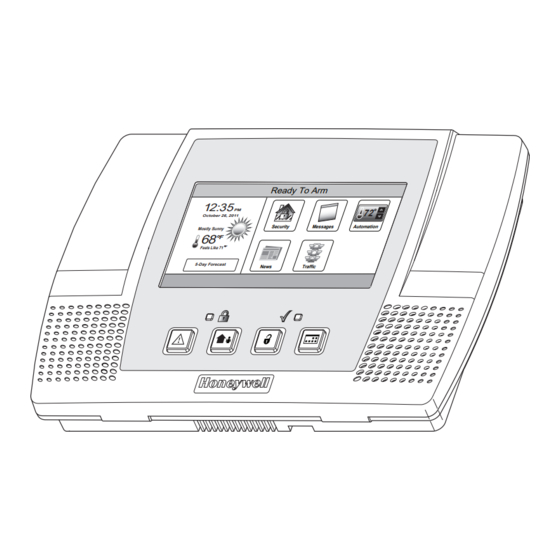
LYNX Touch Security System User Guide Ready To Arm October 26, 2011 Security Messages Automation Mostly Sunny Feels Like 71 5-Day Forecast News Traffic 800-10615 1/12 Rev. A LYNX Touch L5100 Series... - Page 2 Your Honeywell security system is designed for use with devices manufactured or approved by Honeywell for use with your security system. Your Honeywell security system is not designed for use with any device that may be attached to your security system's control or other communicating bus if Honeywell has not approved such device for use with your security system.
-
Page 3: Table Of Contents
National Fire Protection Association’s Smoke Detector Recommendations........72 Emergency Evacuation .........................73 Congratulations on your ownership of a Honeywell Security System. You have made a wise decision in choosing it, for it represents the latest in security protection technology today. Honeywell is the world's largest manufacturer of security system and millions of premises are protected by Honeywell products. - Page 4 TABLE OF CONTENTS TABLE OF CONTENTS TABLE OF CONTENTS TABLE OF CONTENTS SYSTEM FUNCTIONS..........................74 Testing the System..........................74 Maintaining Your System........................77 SUMMARY OF AUDIBLE & VISUAL NOTIFICATIONS ..............79 System Displays ............................80 Zone Status Icons ..........................80 REGULATORY AGENCY STATEMENTS .....................82 OWNER’S INSURANCE PREMIUM CREDIT REQUEST..............85 SERVICING INFORMATION........................86 LIMITATIONS OF THIS ALARM SYSTEM..................87 INDEX ................................93...
-
Page 5: System Overview
SYSTEM OVERVIEW SYSTEM OVERVIEW SYSTEM OVERVIEW SYSTEM OVERVIEW Features General Information This system offers you three forms of protection: burglary, fire, and emergency, depending on the configuration of your system. The system consists of a touch screen control for system operation, various wireless sensors that provide perimeter and interior burglary protection, and optional smoke or combustion detectors to provide early fire warning. - Page 6 SYSTEM OVERVIEW SYSTEM OVERVIEW SYSTEM OVERVIEW SYSTEM OVERVIEW Features • Device activation: Allows you to send “Follow-Me” or e-mail messages, as a result of a system event such as an alarm or trouble condition. Refer to the Rules section for detailed information.
-
Page 7: General Operation
SYSTEM OVERVIEW SYSTEM OVERVIEW SYSTEM OVERVIEW SYSTEM OVERVIEW General Operation Security Codes At the time of installation, you were asked to provide a personal 4-digit security or “Master User” code. You must enter the user code when arming and disarming the system, and when performing other system functions. - Page 8 SYSTEM OVERVIEW SYSTEM OVERVIEW SYSTEM OVERVIEW SYSTEM OVERVIEW General Operation LYNX Touch SIA False Alarm Prevention Features Many false alarms are caused by simple accidents, like forgetting to close a door when you leave. The LYNX Touch SIA includes several features that help prevent false alarms and some of these are optional or programmable.
-
Page 9: Quick View Of System Functions
SYSTEM OVERVIEW SYSTEM OVERVIEW SYSTEM OVERVIEW SYSTEM OVERVIEW Quick View of System Functions SECURITY FUNCTIONS Check System status: ..........Select “System” icon. To arm in STAY mode: ..........Select “Arm Stay” icon then enter Code. To restart exit delay: ........... Select “Restart Exit Delay” icon. To arm in AWAY mode: .......... -
Page 10: About The Touch Screen Control
SYSTEM OVERVIEW SYSTEM OVERVIEW SYSTEM OVERVIEW SYSTEM OVERVIEW About the Touch screen Control General **IMPORTANT** If the LYNX Touch is beeping rapidly upon entering the premises, an alarm has occurred during your absence and an intruder may still be on the premises. LEAVE IMMEDIATELY and CONTACT THE POLICE from a nearby safe location. - Page 11 SYSTEM OVERVIEW SYSTEM OVERVIEW SYSTEM OVERVIEW SYSTEM OVERVIEW About the Touch screen Control Note: The system functions described below are for reference only and require additional key entries to activate. Index Item Description Display Color Liquid Crystal Display (LCD) Touch screen. Displays system status icons, Window time, system status information, user menus and the virtual keypad.
-
Page 12: About The Display And Indicators
SYSTEM OVERVIEW SYSTEM OVERVIEW SYSTEM OVERVIEW SYSTEM OVERVIEW About the Display and Indicators Display Definitions DEFINITION ICON TEXT Displayed along with the the text “Ready To Arm” when Ready to system is Disarmed and ready to arm. “Armed Away” is displayed along the top of the screen. An Armed armed away icon along with “Armed Away”... - Page 13 SYSTEM OVERVIEW SYSTEM OVERVIEW SYSTEM OVERVIEW SYSTEM OVERVIEW About the Display and Indicators DEFINITION ICON TEXT The Medical icon displayed when a medical alarm is activated. Alarm 96 Medical “Alarm” is also displayed in a red band along the top of the screen.
-
Page 14: Navigating Menus
SYSTEM OVERVIEW SYSTEM OVERVIEW SYSTEM OVERVIEW SYSTEM OVERVIEW Navigating Menus LCD Display LYNX Touch’s Liquid Crystal Display (LCD) touch screen displays variable icons and text on “screens”. The screen displays status icons and associated text, the current time, system status information and menu choices. The system status is displayed in a colored band along the top of the screen. -
Page 15: Navigation Keys
SYSTEM OVERVIEW SYSTEM OVERVIEW SYSTEM OVERVIEW SYSTEM OVERVIEW Navigating Menus Navigation Keys Navigating through the screens is accomplished by lightly touching the menu item on the touch screen. Once activated, the control will take you to the next screen. Selecting the “Home”... - Page 16 SYSTEM OVERVIEW SYSTEM OVERVIEW SYSTEM OVERVIEW SYSTEM OVERVIEW Navigating Menus Menu Screens System Status is displayed at the top of each screen. The time and date are displayed at the bottom of the Home Screen. Menus Unrestricted Menu The first page of the Home Screen provides access to an Unrestricted Menu displays the system status and eight selection icons or “buttons”.
- Page 17 SYSTEM OVERVIEW SYSTEM OVERVIEW SYSTEM OVERVIEW SYSTEM OVERVIEW Navigating Menus Master Menu The User Menu provides access to User configurable features and displays eight options. Entering the Master User Code is required to access the Master menu. • Users – Allows Master User to add or remove User Codes. •...
-
Page 18: Securing The Premises
SECURING THE PREMISES SECURING THE PREMISES SECURING THE PREMISES SECURING THE PREMISES System Status General Information Before arming your system, all protected doors, windows, and other protection zones must be closed or bypassed (see the BYPASSING PROTECTION section). Ready LED: The Green (Ready) indicator on the control will be lit if the system is ready to be armed. -
Page 19: Arming The System
SECURING THE PREMISES SECURING THE PREMISES SECURING THE PREMISES SECURING THE PREMISES Arming the System Arming in Stay Mode Use this mode when you are staying home, but expect someone to use the entrance door later. Close all protected perimeter windows and doors before arming. The green Ready indicator on the control should be lit if the system is ready to be armed. - Page 20 SECURING THE PREMISES SECURING THE PREMISES SECURING THE PREMISES SECURING THE PREMISES Arming the System Armed Stay At the end of the exit delay the system announces “Armed Stay” and displays the “Armed Stay” screen. Zones Automation Disarm Message Phone More 10:18 AM June 8, 2010 5000-100-056-V1...
- Page 21 SECURING THE PREMISES SECURING THE PREMISES SECURING THE PREMISES SECURING THE PREMISES Arming the System Arming In Away Mode Use this mode when no one will be staying on the premises. Close all protected perimeter windows and doors before arming. The green Ready indicator on the control should be lit if the system is ready to be armed.
- Page 22 SECURING THE PREMISES SECURING THE PREMISES SECURING THE PREMISES SECURING THE PREMISES Arming the System Armed Away If “Exit Warning” has been enabled, the system will continue to beep throughout the exit delay. Rapid beeps will sound for the final 10 seconds of the delay period. At Zones Automation the end of the exit delay the system will...
-
Page 23: Quick Exit
SECURING THE PREMISES SECURING THE PREMISES SECURING THE PREMISES SECURING THE PREMISES Arming the System Arming the System with no delay (Instant) Use “Instant” with Stay mode when you are staying home and do not expect anyone to use the entrance door. Use “Instant” with Away mode when the premises will be vacant for extended periods of time such as vacations, etc. -
Page 24: Entry/Exit Delays
SECURING THE PREMISES SECURING THE PREMISES SECURING THE PREMISES SECURING THE PREMISES Entry/Exit Delays Entry/Exit Delays Entry/Exit Delays Entry/Exit Delays Exit Delay Exit delay begins immediately after arming the system, and gives you time to leave through the designated exit door without setting off an alarm. The system display will count down the time remaining in the exit delay, if programmed by your installer. - Page 25 SECURING THE PREMISES SECURING THE PREMISES SECURING THE PREMISES SECURING THE PREMISES Entry/Exit Delays Entry/Exit Delays Entry/Exit Delays Entry/Exit Delays system/zone status area. The alarm will continue to sound until the system is disarmed or timeout ocurs. To stop the alarm, the system must be disarmed by selecting the “Disarm” icon OR depressing the “Off”...
-
Page 26: Disarming The System
SECURING THE PREMIS SECURING THE PREMIS SECURING THE PREMIS SECURING THE PREMISES Disarming the System Select the “Disarm” icon or the “Off” key to disarm the system and to silence alarm and trouble sounds. See the Summary of Audible Notification section for information, which will help you to distinguish between fire and burglary alarm sounds. - Page 27 SECURING THE PREMISES SECURING THE PREMISES SECURING THE PREMISES SECURING THE PREMISES Disarming the System Disarming the System During Entry Delay Upon entering the premise when the system is Armed Stay - Disarm Now armed, the control announces “disarm system Disarm Now now”.
-
Page 28: Bypassing Protection Zones
SECURING THE PREMISES SECURING THE PREMISES SECURING THE PREMISES SECURING THE PREMISES Bypassing Protection Zones Bypassing Individual Zones The Bypass feature can be used when you want to intentionally arm your system with one or more zones unprotected. Bypassed zones are unprotected and will not cause an alarm when violated while your system is armed. -
Page 29: Bypassing Protection Zones
SECURING THE PREMISES SECURING THE PREMISES SECURING THE PREMISES SECURING THE PREMISES Bypassing Protection Zones Displaying/Clearing Bypassed Zones Ready To Arm - Bypass 1. With the system in the disarmed state, select the “Zones” icon. The system displays the Zone screen and the status for each zone will be indicated. -
Page 30: Panic Keys
SECURING THE PREMISES SECURING THE PREMISES SECURING THE PREMISES SECURING THE PREMISES Panic Keys Panic Keys Your system may have been programmed to use special keys to manually activate panic functions. The functions that might be programmed are listed below. See your installer for the function(s) that may have been programmed for your system. -
Page 31: Panic Keys
SECURING THE PREMISES SECURING THE PREMISES SECURING THE PREMISES SECURING THE PREMISES Panic Keys Activating a Panic Alarm Ready To Arm 1. With the system in the disarmed or armed state, depress and hold the “Panic” key until the system displays the Panic screen (approximately 3-4 seconds). -
Page 32: Chime Mode
SECURING THE PREMISES SECURING THE PREMISES SECURING THE PREMISES SECURING THE PREMISES Chime Mode Chime Mode Your system can be set to provide you with an audible alert of the opening of a door, while it is disarmed, by using Chime mode. When activated, three beeps will sound at the control whenever a protected perimeter door is opened and the zone voice descriptor will be announced, if programmed. -
Page 33: Voice Mode
SECURING THE PREMISES SECURING THE PREMISES SECURING THE PREMISES SECURING THE PREMISES Voice Mode Voice Mode Your system can be set to provide you with a voice alert of system functions by activating the Voice mode. When activated, the system will announce the system status when armed/disarmed. -
Page 34: User Functions
USER FUNCTIONS USER FUNCTIONS USER FUNCTIONS USER FUNCTIONS User Access General Information For additional security you (the Master User Code) can assign secondary user codes to individual users enabling them to perform specific system functions. These secondary users are identified by "User Numbers" when their codes are assigned. You can assign up to 14 user codes. - Page 35 USER FUNCTIONS USER FUNCTIONS USER FUNCTIONS USER FUNCTIONS User Access Ready To Arm 2. Enter your 4-digit Master User Code. The Program the system system displays Master User programming screen. Enter Code: Cancel Clear 5000-100-009-V0 Ready To Arm 3. Select the “Users” icon. The system displays the Master User screen.
- Page 36 USER FUNCTIONS USER FUNCTIONS USER FUNCTIONS USER FUNCTIONS User Access Ready To Arm 6. If desired you can enter a User Name. Select the “Clear” key and then enter up to 10 characters of text. Note: Select the “ABC…” key to switch the keyboard between upper/lower case or the “123!@#”...
- Page 37 USER FUNCTIONS USER FUNCTIONS USER FUNCTIONS USER FUNCTIONS User Access Editing/Deleting a User Ready To Arm 1. With the system in the disarmed state, select the “Tools” icon from the second page of the Home Screen. The system displays the Keypad screen.
- Page 38 USER FUNCTIONS USER FUNCTIONS USER FUNCTIONS USER FUNCTIONS User Access Ready To Arm 5. If desired you can revise a User Name. Select the “Clear” key and then enter the desired text. 6. Once you are finished, select “Done”. The system displays the Keypad screen.
-
Page 39: View Events
USER FUNCTIONS USER FUNCTIONS USER FUNCTIONS USER FUNCTIONS View Events This feature can be used to view a number of System Events including Arming/Disarming, Zone Activity, Troubles and Alarms. Viewing System Events Ready To Arm 1. With the system in the disarmed state, select the “Tools”... - Page 40 USER FUNCTIONS USER FUNCTIONS USER FUNCTIONS USER FUNCTIONS View Events Ready To Arm 4. If you wish to view specific system history, select “All”. The system displays a new Sun Jun 13, 2010 15:08 Sat Jun 12, 2010 11:15 Disarmed Armed Stay menu.
-
Page 41: Message Recording And Playback
USER FUNCTIONS USER FUNCTIONS USER FUNCTIONS USER FUNCTIONS Message Recording and Playback The LYNX Touch Message Center allows you to record, play and delete messages. The maximum message duration is 184 seconds. NOTES: (1) If the system loses electrical power, all messages will be erased. (2) Message Play/Record will not be available if a report must be sent. - Page 42 USER FUNCTIONS USER FUNCTIONS USER FUNCTIONS USER FUNCTIONS Message Recording and Playback 6. When you have finished recording, select Ready To Arm “ ”. The system displays the recorded Message 1 2:48 PM September 1, 2010 messages. 7. To record additional messages (if recording Message 2 5:09 PM September 5, 2010...
-
Page 43: System Settings
USER FUNCTIONS USER FUNCTIONS USER FUNCTIONS USER FUNCTIONS System Settings The volume level of message playback, system announcements, and status beeps can be changed if desired. Additionally, you can adjust the display’s brightness and contrast and turn on or off the Chime or turn off the telephone Ringer. Change System Settings Ready To Arm 1. -
Page 44: Clock/Calendar
USER FUNCTIONS USER FUNCTIONS USER FUNCTIONS USER FUNCTIONS Clock/Calendar Note: If your system is equipped with a GSMVLP5 or ILP5 Communication Module, the time and date will be programmed and updated automatically via Central Station. You may still program the correct Time Zone as shown below. - Page 45 USER FUNCTIONS USER FUNCTIONS USER FUNCTIONS USER FUNCTIONS Clock/Calendar System Programming... 4. Select the correct month by using the “ ” and “ ”. June 2010 5. Select the correct year by using the “ ” and S U N M O N T U E W E D...
- Page 46 USER FUNCTIONS USER FUNCTIONS USER FUNCTIONS USER FUNCTIONS Clock/Calendar Ready To Arm 12. Select “Start Month”. The system displays a calendar. Select the correct month. January February 13. Select “Start Week”. The system will toggle between: March April Second Third June Fourth Last...
-
Page 47: Automation
USER FUNCTIONS USER FUNCTIONS USER FUNCTIONS USER FUNCTIONS Automation General Information Automation is used to program triggers, home automation features, send Follow-Me or E- mail messages of system events or program home automation features (Z-Wave) including Rules and Scenes (if Z-Wave communications have been enabled). Up to 40 rules can be programmed. - Page 48 USER FUNCTIONS USER FUNCTIONS USER FUNCTIONS USER FUNCTIONS Automation Ready To Arm 2. Select the “Rules” button. The system displays the Rules screen. Switches Rules Thermostat Schedules Locks Scenes Tools 5100-100-007-V0 Ready To Arm 4. Select a “Rules” key followed by the Edit button.
- Page 49 USER FUNCTIONS USER FUNCTIONS USER FUNCTIONS USER FUNCTIONS Automation 7. Select “Action”. Dependant upon the Type Ready To Arm selected previously, the system scrolls between Name several options: None Type Action Permanent On Trigger Output None On for 2 sec Start Zone Type Stop Zone Type Pulsing...
- Page 50 USER FUNCTIONS USER FUNCTIONS USER FUNCTIONS USER FUNCTIONS Automation Ready To Arm 9. Select “Stop Zone Type” or “Zone Type Restore” (if “Scene” was selected in Type field). Name The system displays the same options as the previous step. Type Action Trigger Output None...
- Page 51 USER FUNCTIONS USER FUNCTIONS USER FUNCTIONS USER FUNCTIONS Automation 13. Select the First, Second or Third “Start Zone” or Ready To Arm “Zone Fault” (The name of this field is Zone Number Operation dependant upon the “Type” that was selected in Fault Step 6.) Select the Zone from the list displayed First Start Zone...
- Page 52 USER FUNCTIONS USER FUNCTIONS USER FUNCTIONS USER FUNCTIONS Automation Schedules The Schedules Feature can be used to program the system to automatically perform certain functions (i.e.; automatically arming the system in Stay mode and activating output [Z- Wave] devices). Programming a Scheduled Function Ready To Arm 1.
- Page 53 USER FUNCTIONS USER FUNCTIONS USER FUNCTIONS USER FUNCTIONS Automation 4. Select “Name”. The system displays a Ready To Arm keypad. Name Frequency None Type None Save 5000-100-144-V0 5. Enter a name (up to 13 digits long) for the Ready To Arm scheduled function on the displayed keypad then select “Done”.
- Page 54 USER FUNCTIONS USER FUNCTIONS USER FUNCTIONS USER FUNCTIONS Automation Ready To Arm 9. If Auto Stay is selected, select “Clear” then enter a 4-digit time on the displayed keypad then select “Save”. If “Rules” is selected proceed to Step 11. If “Disarm Notification” is selected proceed to Step 12.
-
Page 55: Reminders
USER FUNCTIONS USER FUNCTIONS USER FUNCTIONS USER FUNCTIONS Automation Scenes Scenes are used to control a single or group of devices together, turning them OFF, ON, ON to a preset lighting level, temperature or mode, or lock/unlocked. The LYNX Touch has 20 Scenes which may each be configured with up to 10 devices each. - Page 56 USER FUNCTIONS USER FUNCTIONS USER FUNCTIONS USER FUNCTIONS Automation Select the “Add New Device” button. The Ready To Arm system displays the available Z-Wave Switches device types. Select one of the following options: Switches Thermostat Thermostats Locks Locks 5. Select the desired device type, then select the applicable device from the list of installed devices.
- Page 57 USER FUNCTIONS USER FUNCTIONS USER FUNCTIONS USER FUNCTIONS Automation Editing/Deleting a Scene Ready To Arm 1. With the system in the disarmed state, select the “Automation” icon from the Home Screen. The system displays the Keypad screen. Zones Automation Arm Away Arm Stay Phone Message...
- Page 58 USER FUNCTIONS USER FUNCTIONS USER FUNCTIONS USER FUNCTIONS Automation Running a Scene Ready To Arm 1. With the system in the disarmed state, select the “Automation” icon from the Home Screen. The system displays the Keypad screen. Zones Automation Arm Away Arm Stay Message Phone...
- Page 59 USER FUNCTIONS USER FUNCTIONS USER FUNCTIONS USER FUNCTIONS Reminders The Reminder Feature can be used to program/record reminders that can be displayed on the touch screen, announced by the control and/or sent to one or two pre-programmed phone number(s). Check with your installer to see if the latter feature has been programmed on your control.
- Page 60 USER FUNCTIONS USER FUNCTIONS USER FUNCTIONS USER FUNCTIONS Reminders Ready To Arm 4. Select “Add New”. The system displays the Reminder programming screen. No items to display! Edit Add New Delete 5000-100-178-V0 Ready To Arm 5. Select “Name”. Enter a name for the scheduled function on the displayed keypad Name Frequency...
- Page 61 USER FUNCTIONS USER FUNCTIONS USER FUNCTIONS USER FUNCTIONS Reminders Ready To Arm 10. If a “Follow Me” phone number(s) was programmed by your installer you can send Name Frequency Walk Dog Once a reminder to the phone number(s). Select “Follow Me” option. The system toggles Date between “Disabled”, “To Ph.
-
Page 62: Wifi Configuration
USER FUNCTIONS USER FUNCTIONS USER FUNCTIONS USER FUNCTIONS WiFi Configuration View/Join Available WiFi Networks Ready To Arm 1. At the Master User screen select the WiFi Config icon. The system displays the WiFi options screen. Users Test Keypad Events Date Time Reminders Slide Show WiFi Config... - Page 63 USER FUNCTIONS USER FUNCTIONS USER FUNCTIONS USER FUNCTIONS WiFi Configuration Manually Configure Access Point Ready To Arm 1. At the Master User screen select the WiFi Config icon. The system displays the WiFi options screen. Users Test Keypad Events Date Time Reminders Slide Show WiFi Config...
- Page 64 USER FUNCTIONS USER FUNCTIONS USER FUNCTIONS USER FUNCTIONS WiFi Configuration Enrolling/Syncing Auxiliary Keypads The LYNX Touch will support up to four Mobile Internet Devices (MID) (or tablets) that can be used as auxiliary keypads. A WiFi communication device is required. The “Keypad” button is used to enroll/sync the MID with the control.
-
Page 65: Speaker Phone
USER FUNCTIONS USER FUNCTIONS USER FUNCTIONS USER FUNCTIONS Speaker Phone Feature If this feature has been programmed the LYNX Touch is capable of operating as a speaker phone. During speaker phone operation the system will provide the following functions: • All function/event processing will continue to operate, but there will be no announcements. - Page 66 USER FUNCTIONS ER FUNCTIONS ER FUNCTIONS ER FUNCTIONS Speaker Phone Feature Placing a Call Ready To Arm 1. With the system in the disarmed or armed state, select the “Phone” icon from the Home Screen. The system displays the Keypad screen. Zones Automation Arm Away...
-
Page 67: Remote Phone Control
USER FUNCTIONS USER FUNCTIONS USER FUNCTIONS USER FUNCTIONS Remote Phone Control Feature The LYNX Touch Series is equipped with a remote interactive phone capability that permits access to the security system from any off-site touch-tone telephone using all user codes. The system will provide the appropriate voice messages and any system beeping sounds indicating the status of the security system over the phone line. -
Page 68: Remote Services
USER FUNCTIONS USER FUNCTIONS USER FUNCTIONS USER FUNCTIONS Remote Services Your security system may be capable of providing a series of web-based services that allow you to communicate with your security system remotely in a number of ways. These services provide the ability to: •... -
Page 69: Slide Show
USER FUNCTIONS USER FUNCTIONS USER FUNCTIONS USER FUNCTIONS Slide Show The LYNX Touch features a Slide Show/Screen Saver feature. The feature allows images to be displayed on the touch screen when it is not in use. Connection to Total Connect Service is required in order for your installer to upload images to your panel. - Page 70 USER FUNCT USER FUNCT USER FUNCT USER FUNCTIONS IONS IONS IONS Slide Show Ready To Arm 4. Select the “Slide Show” icons that you do not wish to display or select “Delete All”. Use the “ ” “ ” buttons to scroll to second and subsequent pages of screens.
-
Page 71: Fire/Co Alarm System
FIRE FIRE FIRE FIRE/CO /CO ALARM SYSTEM ALARM SYSTEM ALARM SYSTEM (If Installed) ALARM SYSTEM General Information LYNX Touch is not intended for UL985 Household Fire applications unless a 24-hour backup battery (P/N LYNXRCHKIT-SHA) is installed. General Your fire alarm system (if installed) is active 24 hours a day, providing continuous protection. -
Page 72: National Fire Protection Association's Smoke Detector Recommendations
FIRE FIRE FIRE FIRE/CO /CO ALARM SYSTEM ALARM SYSTEM ALARM SYSTEM ALARM SYSTEM National Fire Protection Association’s Smoke Detector Recommendations LYNX Touch is not intended for UL985 Household Fire applications unless a 24-hour backup battery (P/N LYNXRCHKIT-SHA) is installed. With regard to the number and placement of smoke and heat detectors, we subscribe to the recommendations contained in the National Fire Protection Association's (NFPA) Standard #72 noted below. -
Page 73: Emergency Evacuation
FIRE FIRE FIRE FIRE/CO /CO ALARM SYSTEM ALARM SYSTEM ALARM SYSTEM ALARM SYSTEM Emergency Evacuation LYNX Touch is not intended for UL985 Household Fire applications unless a 24-hour backup battery (P/N LYNXRCHKIT-SHA) is installed. Establish and regularly practice a plan of escape in the event of fire. The following steps are recommended by the National Fire Protection Association: 1. -
Page 74: System Functions
SYSTEM FUNCTIONS Testing the System (to be conducted weekly) Test Modes The Test icon provides access to the Walk Test, Dialer Test and Reboot functions. The Walk Test mode allows each protection point to be checked for proper operation. When the Walk Test mode is active, the control sounds a single beep every 30 seconds as a reminder that the system is in the Test mode. -
Page 75: System Functions
SYSTEM FUNCTIONS Testing the System (to be conducted weekly) Ready To Arm 3. Select the “Test” icon. The system displays the Test screen. Users Test Keypad Events Date Time Reminders Slide Show WiFi Config Back 5100-100-006-V0 Ready To Arm 4. Select the “Walk Test”, “Dialer Test” or “Reboot”... - Page 76 SYSTEM FUNCTIONS Testing the System (to be conducted weekly) If a problem is experienced with any protection point (no confirming sounds, no display), notify your service company. When all protection points have been checked and are intact (closed), there should be no zone identification numbers displayed on the touch screen.
-
Page 77: Maintaining Your System
SYSTEM FUNCTIONS Maintaining your system The components of your security system are designed to be as maintenance-free as possible. To make sure that your system is in working condition, do the following: 1. Test your system weekly (see the TESTING THE SYSTEM section). 2. - Page 78 SYSTEM FUNCTIONS Maintaining your system Low Battery Conditions in Wireless Sensors Each wireless sensor in your system has an internal battery. The system detects low battery conditions in wireless sensors, including smoke detectors, personal emergency transmitter, and the portable wireless keypad, and displays a “Battery Low” message on the touch screen, which also beeps.
-
Page 79: Summary Of Audible & Visual Notifications
SUMMARY OF AUDIBLE & VISUAL NOTIFICATIONS SOUND CAUSE ANNOUNCEMENT* INTERRUPTED FIRE ALARM (3 beeps) fire alarm + zone voice descriptor CARBON MONOXIDE ALARM (4 beeps) Carbon monoxide alarm + zone voice descriptor (Voice descriptor is interlaced with the sounder and sounds every 45 seconds) CONTINUOUS BURGLARY/AUDIBLE EMERGENCY alarm + zone voice descriptor... -
Page 80: System Displays
SUMMARY OF AUDIBLE & VISUAL NOTIFICATIONS System Displays The following icons will be displayed on the Home screen along with specific zone status information (if applicable) to indicate system status. DISPLAY DEFINITION DISPLAY DEFINITION AC Loss Door Open Alarm Window Open (intrusion) Armed Away Exit Active... - Page 81 SUMMARY OF AUDIBLE & VISUAL NOTIFICATIONS Zone Status Icons The following icons may be displayed on the Zone Status screen. DEFINITION DEFINITION ICON ICON Alarm Trouble (red) Fault (Yellow) Bypass Ready LED Meanings Armed LED (Red): ON = System armed OFF = System disarmed Blinking = System armed, but a fault exists or alternating with Ready LED when AVM (VOX or Talk) or speaker phone mode is active.
-
Page 82: Regulatory Agency Statements
REGULATORY AGENCY STATEMENTS Federal Communications Commission (FCC) Part 15 The user shall not make any changes or modifications to the equipment unless authorized by the Installation Instructions or User's Manual. Unauthorized changes or modifications could void the user's authority to operate the equipment. CLASS B DIGITAL DEVICE STATEMENT NOTE: This equipment has been tested and found to comply with the limits for a Class B digital device, pursuant to part 15 of the FCC Rules. - Page 83 REGULATORY AGENCY STATEMENTS TELEPHONE/MODEM INTERFACE Federal Communications Commission (FCC) Part 68 This equipment complies with Part 68 of the FCC rules. On the front cover of this equipment is a label that contains the FCC registration number and Ringer Equivalence Number (REN). You must provide this information to the telephone company when requested.
-
Page 84: In The Event Of Telephone Operational Problems
IN THE EVENT OF TELEPHONE OPERATIONAL PROBLEMS In the event of telephone operational problems, disconnect the control by removing the plug from the RJ31X (CA38A in Canada) telephone wall jack. We recommend that your certified installer demonstrate disconnecting the phones on installation of the system. Do not disconnect the phone connection inside the control/communicator. -
Page 85: Owner's Insurance Premium Credit Request
OWNER'S INSURANCE PREMIUM CREDIT REQUEST This form should be completed and forwarded to your homeowner's insurance carrier for possible premium credit. A. GENERAL INFORMATION: Insured's Name and Address: Insurance Company: Policy No.: LYNX Touch Series _________________________________________________ Other Type of Alarm: Burglary Fire Both... - Page 86 OWNER'S INSURANCE PREMIUM CREDIT REQUEST (cont.) E. SMOKE DETECTOR LOCATIONS Furnace Room Kitchen Bedrooms Attic Basement Living Room Dining Room Hall F. BURGLARY DETECTING DEVICE LOCATIONS: Front Door Basement Door Rear Door All Exterior Doors 1st Floor Windows All Windows Interior Locations All Accessible Openings, Including Skylights, Air Conditioners and Vents G.
-
Page 87: Servicing Information
SERVICING INFORMATION Your local Honeywell dealer is the person best qualified to service your alarm system. Arranging some kind of regular service program with him is advisable. Your local Honeywell dealer is: Name: Address: Phone: – 87 –... -
Page 88: Limitations Of This Alarm System
WARNING! THE LIMITATIONS OF THIS ALARM SYSTEM While this system is an advanced design security system, it does not offer guaranteed protection against burglary or fire or other emergency. Any alarm system, whether commercial or residential, is subject to compromise or failure to warn for a variety of reasons. - Page 89 – NOTES – – 89 –...
- Page 90 – NOTES – – 90 –...
- Page 91 – NOTES – – 91 –...
- Page 92 – NOTES – – 92 –...
-
Page 93: Index
– INDEX – Alarm Cancelled ........8, 24, 25 E-Mail Events ..........47 Alarm Exit Error ..........24 Entering Test Mode .........74 Alarms..............7 Entry Delay....6, 11, 19, 21, 23, 24, 25 Armed Indicator ..........23 Exit Alarms..........8, 24 Armed LED Indicator........11 Exit Delay ............24 Audible Emergency/Audible Alarm ....30 Exit Time Restart-Exit Delay Restart/Reset..8 Auto Stay Feature ........8, 20... - Page 94 Quick Arm..........9, 19, 21 Tablets..............64 Quick Exit ............23 Test Mode..........9, 74, 76 Time And Date........9, 16, 44 Touchscreen Control......5, 10, 11 Two-Way Voice..........5, 7 Ready Indicator ......18, 19, 21, 26 Ready LED............18 Ready LED Indicator........11 Real-Time Clock ..........5 Unrestricted Menu ..........16 Reboot ............74, 75 User Access ............34 Rechargeable, Nickel-Metal Hydride Battery...
-
Page 95: Two Year Limited Warranty
TWO YEAR LIMITED WARRANTY Honeywell International Inc., acting through its Security & Communications business (“Seller”), 2 Corporate Center Drive, Melville, New York 11747 warrants its products to be free from defects in materials and workmanship under normal use and service, normal wear and tear excepted, for 24 months from the manufacture date code; provided,... - Page 96 2 Corporate Center Drive, Suite 100 P.O. Box 9040, Melville, NY 11747 Copyright © 2012 Honeywell International Inc. www.honeywell.com/security Ê800-10615ÄŠ 800-10615 1/12 Rev. A...
Need help?
Do you have a question about the LYNX Touch Security System and is the answer not in the manual?
Questions and answers