Honeywell NetAXS-123 Installation Manual
Access control unit
Hide thumbs
Also See for NetAXS-123:
- User manual (171 pages) ,
- Quick start up manual (49 pages) ,
- Startup manual (24 pages)

Related Manuals for Honeywell NetAXS-123


Summary of Contents for Honeywell NetAXS-123
-
Page 1: Installation Guide
NetAXS-123 Access Control Unit Installation Guide May 2010 © 2010 Honeywell. All rights reserved. 800-05779, Revision A... - Page 2 Ordering Information Please contact your local Honeywell representative or visit us on the web at www.honeywellaccess.com for information about ordering. Feedback Honeywell appreciates your comments about this manual. Please visit us on the web at www.honeywellaccess.com to post your comments.
-
Page 3: Table Of Contents
3.7 Communications ......................42 USB Communications ....................42 RS-485 Communications ....................44 Ethernet TCP/IP Communications ................47 4.0 System Configuration ........................4.1 Ethernet Connection ......................48 4.2 USB Connection ......................49 NetAXS-123 Access Control Unit Installation Guide, Document 800-05779, Revision A... - Page 4 4.6 M-56K Dial-up Modem, RS-485 Connection via Hub (PCI-3) ........54 4.7 Fiber Converter to RS-485 Connection via PCI-3............55 4.8 Fiber Converter to RS-485 Connection via NetAXS-123 ..........56 4.9 N-485-PCI-3/NetAXS-123 Access Controller Panel Connection Detail ......57 4.10 NetAXS-123/NetAXS-123 Access Controller Panel Connection Detail ...... 58 4.11 Mixed Loops ........................
- Page 5 Figure 14: RS-485 Connection via PCI-3 ................50 Figure 15: RS-485 Connection via NetAXS-123 ..............51 Figure 16: RS-485 Connection via NetAXS-123 with Multidrop Panels at Both Ends ..52 Figure 17: RS-485 Connection via PCI-3 with Multidrop Panels at Both Ends ...... 53 Figure 18: M-56K Dial-up Modem, RS-485 Connection via Hub ...........
- Page 6 www.honeywell.com...
- Page 7 Table 8: NetAXS-123 SW1 DIP Switch Settings ..............36 Table 9: NetAXS-123 SW2 DIP Switch Settings ..............38 Table 10: Reader Wiring ......................62 Table 11 Troubleshooting Problems and Solutions ..............65 NetAXS-123 Access Control Unit Installation Guide, Document 800-05779, Revision A...
- Page 8 www.honeywell.com...
- Page 9 Installing the NetAXS-123 Panels In this chapter ... Introduction Panel Components and Descriptions Installation System Configuration Hardware Specifications Maintenance Troubleshooting Technical Support NetAXS-123 Access Control Unit Installation Guide, Document 800-05779, Revision A...
-
Page 10: Installing The Netaxs-123 Panels
Installing the NetAXS-123 Panels Introduction 1.0 Introduction This document describes how to install the NetAXS-123 Standard Enclosure access control unit and the NetAXS-123 Compact Enclosure access control unit. 1.1 Access Control Overview An access control system protects and preserves an enterprise’s resources by providing authentication, authorization, and administration services. -
Page 11: Panel Components And Descriptions
The NetAXS-123 panel consists of a web-browser-enabled controller, a one- or two-door add-on board that supports additional inputs and outputs, a power-over-Ethernet (PoE) power supply (NetAXS-123 Compact only), and a battery (NetAXS-123 Standard only). -
Page 12: Figure 2: Netaxs-123 Standard Enclosure Panel Wiring And Components
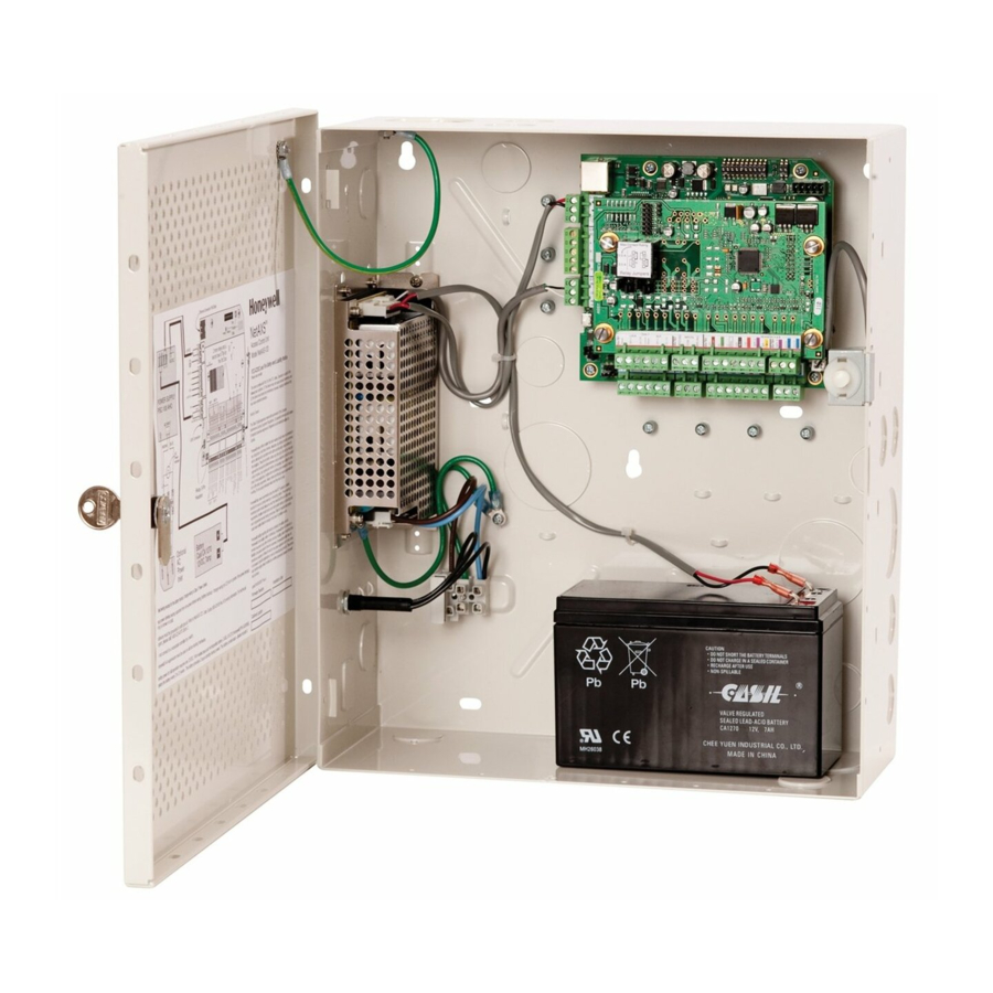
Installing the NetAXS-123 Panels Panel Components and Descriptions Figure 2: NetAXS-123 Standard Enclosure Panel Wiring and Components Maintain at least a .25-inch distance between the non-power limited wiring (115 VAC/60 Hz Note: input wiring, power line filter wiring, and battery backup/charger wiring) and all other wiring, which is power-limited Class 2 wiring. -
Page 13: Supervised Input Wiring
The supervised inputs are located on the following terminal blocks: Table 1: Supervised Input Terminal Blocks Board Configuration Terminal Block 1-Door (Controller Board) C-TB2 C-TB10 1-Door (Add-On Board) IO-TB2 2-Door (Add-On Board) IO-TB2 (as 1-door Add-On Board) IO-TB6 NetAXS-123 Access Control Unit Installation Guide, Document 800-05779, Revision A... -
Page 14: Figure 4: Typical Supervised Input Wiring Diagram
The following figure shows the typical wiring for a supervised input. Figure 4: Typical Supervised Input Wiring Diagram The figure above shows standard 2,200 ohm resistors. The NetAXS-123 panel accepts 1,000, 2,200, 4,700, or 10,000 ohm values. Note that both resistors must have the same value. -
Page 15: Netaxs-123 Access Control Unit
2.2.1 NetAXS-123 Add-On Board The NetAXS-123 Add-On Board enables you to expand from one door to either two or three doors. The board easily connects to the NetAXS-123 controller board (see the NetAXS-123 Add-On Board Installation Guide (800-05787). -
Page 16: Supported Readers
Installing the NetAXS-123 Panels Panel Components and Descriptions 2.2.2 Supported Readers Supported readers include the following: Table 4: Readers Supported by NetAXS-123 Series Reader Model Honeywell Part Number OmniProx OP-10 OP10GENE OP10HONE OP-30 OP30GENE OP30HONE OP-40 OP40GENE OP40HONE OP-45 OP45GENE... -
Page 17: Real-Time Clock Protection
The NetAXS-123 Compact Enclosure is powered by Power Over Ethernet (PoE) injector. This PoE injector can supply a total system current of 800mA to 900mA @ 12VDC. However the NetAXS-123 controller board consumes 400mA of current, and it therefore leaves 450mA of total current for the 12VDC external power. -
Page 18: Battery
Panel Components and Descriptions 2.4 Battery For the NetAXS-123 Standard Enclosure panel, one CASIL CA1270, 12 VDC, 7A-hour sealed lead-acid battery (Honeywell order number 3-000066). The battery provides standby backup power, depending upon system configuration and activity. When AC is lost, the power supply automatically switches to the backup battery for continuous 12VDC power. -
Page 19: Installation
Installing the NetAXS-123 Panels Installation 3.0 Installation 3.1 Installing the Compact Enclosure Panel Perform the following steps to install the NetAXS-123 Compact panel: Use a static strap whenever touching the panel to ensure protection from Electrostatic Warning: Discharge (ESD). 3.1.1 Installing on a Wall 1. - Page 20 Installing the NetAXS-123 Panels Installation 3. Mount the board onto the back of the panel. 4. Choose the tamper type (standard or off-the-wall tamper) and wire the tamper. • Wiring a standard tamper: www.honeywell.com...
- Page 21 Installing the NetAXS-123 Panels Installation • Wiring an off-the-wall tamper: 5. Set the tamper, using pliers at the four locations indicated below. Do not apply power at this time. Warning: NetAXS-123 Access Control Unit Installation Guide, Document 800-05779, Revision A...
- Page 22 7. Set DIP switch settings for the panel address, communication termination and biasing. See Switch Settings, page 36. 8. Check all wiring at this time. Improper wiring can cause damage to the NetAXS-123 at power up and result in a loss Caution: of warranty. 9. Apply power to the panel.
-
Page 23: Installing Over A Gang Box
3. Pull the wires from the gang box through the knockout holes in the base of the enclosure. 4. Perform steps 3 through 10 in the preceding section ( Installing on a Wall, page 11) to complete the installation of the panel over a gang box. NetAXS-123 Access Control Unit Installation Guide, Document 800-05779, Revision A... -
Page 24: Installing On A Flat Surface
Installing the NetAXS-123 Panels Installation 3.1.3 Installing on a Flat Surface 1. Review the panel layout, cable runs, and power needs. 2. Mount the back of the enclosure on the surface, either with drywall screes or threaded wall anchors. 3. Break off the appropriate plastic wiring tabs, using pliers. -
Page 25: Installing The Standard Enclosure Panel
Installing the NetAXS-123 Panels Installation 3.2 Installing the Standard Enclosure Panel Perform the following steps to install the NetAXS-123 Standard Enclosure panel: Use a static strap whenever touching the panel to ensure protection from Electrostatic Warning: Discharge (ESD). 1. (Optional) Remove the green ground wire and the door. - Page 26 Installing the NetAXS-123 Panels Installation 3. Install the power supply. a. Fit the power supply screws through the key holes in the left side of the cabinet, and seat the power supply by pulling down. b. From the outside of the cabinet, tighten the screws to lock the power supply in place.
- Page 27 Inside the cabinet, screw in the two self-tapping screws (supplied in the product box) at the top and bottom of the power supply. These screws must be installed to ground the power supply to the enclosure. Warning: NetAXS-123 Access Control Unit Installation Guide, Document 800-05779, Revision A...
- Page 28 Installing the NetAXS-123 Panels Installation d. Plug the connector that is attached to the blue and brown wires into the power supply. www.honeywell.com...
- Page 29 • Through the optional AC input receptacle. Note: the brown and blue wires must be twisted together from the point of entry at the AC input receptacle to the Terminal Block. NetAXS-123 Access Control Unit Installation Guide, Document 800-05779, Revision A...
- Page 30 Installing the NetAXS-123 Panels Installation 5. Use a pencil to mark the location of the holes on the wall. 6. Screw the NetAXS-123 Controller Board with the four captive screws www.honeywell.com...
- Page 31 Controller Board. Secure the Add-On Board onto the Controller Board with the four captive finger screws. For more explanation of the Add-On Board installation, see the next section, Installing the Add-On Board. NetAXS-123 Access Control Unit Installation Guide, Document 800-05779, Revision A...
- Page 32 8. Connect the wiring harness, as shown. DO NOT CONNECT the AC power or the battery wires yet! Warning: 9. Power up the NetAXS-123 Controller Board and configure the system. Refer to the NetAXS-123 Startup Guide (800-05780) for instructions. www.honeywell.com...
- Page 33 Installing the NetAXS-123 Panels Installation 10.Connect the battery. 11.Attach the door to the cabinet. 12.Re-connect the green ground wire to the cabinet door. NetAXS-123 Access Control Unit Installation Guide, Document 800-05779, Revision A...
-
Page 34: Installing The Add-On Board
To prevent damage to the NXC1 Controller Board, remove power from the Warning: NetAXS-123 panel before installing or removing a NetAXS-123 Add-On Board. 1. On the NetAXS-123 Controller Board, locate the four posts called out in the image shown below: NetAXS-123 Controller Board... - Page 35 2. Pick up the Add-On Board and notice the four posts on the bottom. 3. Seat the Add-On Board posts into the four posts on the NetAXS-123 Controller Board, aligning the terminal-block edge of the Add-On Board with the terminal-block edge of the Controller Board.
- Page 36 Installing the NetAXS-123 Panels Installation 5. Set the relay jumpers. a. Use the following figure to locate the jumpers. b. See Add-On Board DIP Switch and Jumper Settings, page 40, to set the power source (12VDC power or external power) and the relay contact position (Normally Open or Normally Closed).
-
Page 37: Wiring The Readers
The following three tables list the factory controller board I/O default settings for door-1, door-2, and door-3 configurations. These are the mappings for readers, inputs, and outputs. Reader A and Reader B share many common connections. NetAXS-123 Access Control Unit Installation Guide, Document 800-05779, Revision A... -
Page 38: Table 5: Factory Default Configuration Settings For Door 1
Installing the NetAXS-123 Panels Installation Table 5 shows the input/output factory default wiring for a one-door configuration on the Controller Board. Table 5: Factory Default Configuration Settings for Door 1 Type Purpose Terminal Reader A Reader B Other Default Block... -
Page 39: Table 6: Factory Default Configuration Settings For Door 2
Output #8 IO-TB3 Output 8 Output 8 AUX Relay Output #9 IO-TB1 Output 9 Reader Future IO-TB3 Output 10 Output 10 Buzzer Feature Readers A and B share the same connection. NetAXS-123 Access Control Unit Installation Guide, Document 800-05779, Revision A... -
Page 40: Table 7: Factory Default Configuration Settings For Door 3
Installing the NetAXS-123 Panels Installation Table 7 lists the factory Add-On Board default settings for a door 3. These mappings should be used for the readers, inputs, and outputs when either a 1- or 2-door Add-On Board is attached to the board-to-board connector on the controller board. -
Page 41: Wiring Door Strikes
Installing the NetAXS-123 Panels Installation • NetAXS-123 supports a variety of Wiegand reader models. Some readers have only one brown wire for LED control; others have two possible LED control inputs--orange for the green LED and brown for the red LED. RED is the normal state of the Reader LED operation. The LED turns GREEN for two seconds after a valid card read. - Page 42 Installing the NetAXS-123 Panels Installation 2. Use the following figure to wire the door strike/mag lock according to the power supply used. Be sure to use the S4 suppressor kits as shown below. On-Board External +12VDC Power Supply Configuration Configuration...
-
Page 43: Setting Dip Switches And Jumpers
3.6.1 Controller Board DIP Switch and Jumper Settings Figure 6 locates the NetAXS-123 DIP switch panel and the output 1 and output 3 relay jumpers. Figure 6: Controller Board DIP Switch and Jumper Location NetAXS-123 Access Control Unit Installation Guide, Document 800-05779, Revision A... -
Page 44: Table 8: Netaxs-123 Sw1 Dip Switch Settings
Installing the NetAXS-123 Panels Installation DIP Switch Settings Use the following DIP switch configurations to set the panel address. Table 8: NetAXS-123 SW1 DIP Switch Settings Selection Address 1 (default) Address 2 Address 3 Address 4 Address 5 Address 6... - Page 45 (EOL) ENABLED (Default) OFF Future Use (Default) Future Use a. DIP Switch 7 does NOT require a panel reboot to take effect. This does not affect the USB IP address. NetAXS-123 Access Control Unit Installation Guide, Document 800-05779, Revision A...
-
Page 46: Table 9: Netaxs-123 Sw2 Dip Switch Settings
Installing the NetAXS-123 Panels Installation b. Both DIP Switch 8 and DIP Switch 9 need to be either ON or OFF to be properly configured. Table 9: NetAXS-123 SW2 DIP Switch Settings Selection RS-485_2 termination (EOL) DISABLED RS-485_2 termination (EOL) ENABLED (FUTURE) (Default) a. -
Page 47: Figure 7: Netaxs-123 Controller Board Jumpers
Installation Jumper Settings The NetAXS-123 Controller Board provides two jumper sets, one each for output relay 1 and output relay 3. Each relay has two 3-pin jumpers associated with it. One jumper selects either external power (EXT) or self-whetted (on-board, +12V) power to be applied to the relay contact load. The other jumper is used to select Normally Open (NO) or Normally Closed (NC) relay contacts. -
Page 48: Add-On Board Dip Switch And Jumper Settings
Normally Closed 3.6.2 Add-On Board DIP Switch and Jumper Settings Figure 8 locates the NetAXS-123 Add-On Board DIP switch panel and the output 1 and output 3 relay jumpers. Figure 8: Add-On Board DIP Switch and Jumper Location The figure above shows a one-door Add-On Board configuration. If you are instead using a... - Page 49 3-pin jumpers (two per relay) on the controller board. • Setting the jumpers to configure the power source: External • Setting the jumpers to configure the relay position: Normally Open Normally Closed NetAXS-123 Access Control Unit Installation Guide, Document 800-05779, Revision A...
-
Page 50: Communications
3.7 Communications 3.7.1 USB Communications The NetAXS-123 Controller Board provides a version 2.0 USB port that connects to the web browser or to a WIN-PAK host. The following figure identifies the location of the port on the board. USB communication requires the USB A to MicroUSB B cable that is supplied with the panel. - Page 51 Next If confirmation dialog boxes pop up before or during the installation, click the Note: appropriate boxes to allow or approve the installation. 4. Click to initiate the installation. Install NetAXS-123 Access Control Unit Installation Guide, Document 800-05779, Revision A...
-
Page 52: Rs-485 Communications
For login information, go to https://192.168.2.150. 3.7.2 RS-485 Communications If a NetAXS-123 panel is to be placed onto a prexisting RS-485 dropline loop (NetAXS) it must be setup as the Gateway panel. The interface allows the wiring of a Multidrop communication network of up to 4,000 feet (1200 m) in length. -
Page 53: Figure 9: Rs-485 Configuration Via N-485-Pci-3
If an RS-485 network has a NetAXS-123 Gateway panel, no N1000-II, N1000-III, N1000-IV, or Note: NS2 are allowed on the same network. If they are added to a network with a NetAXS-123 Gateway panel, they will not be able to communicate with the host computer. In order to use these panels, a N-485-PCI-3 is required, as shown in Figure 9. -
Page 54: Figure 10: Rs-485 Configuration Via Netaxs-123 Gateway
Installing the NetAXS-123 Panels Installation Figure 10: RS-485 Configuration via NetAXS-123 Gateway Reader 1 Ethernet NetAXS-123 Gateway Terminal RS-485 Multidrop Line Reader 4 Reader 3 Reader 4 This configuration supports a total of 31 NetAXS and NetAXS-123 panels per Multidrop line. www.honeywell.com... -
Page 55: Ethernet Tcp/Ip Communications
Reader 4 This configuration supports a total of 31 NetAXS and NetAXS-123 panels per Multidrop line. Each NetAXS-123 panel has a port for an Ethernet TCP/IP interface. The Ethernet TCP/IP interface provides 10/100 MB Ethernet support for each panel. NetAXS-123 Access Control Unit Installation Guide, Document 800-05779, Revision A... -
Page 56: System Configuration
Installing the NetAXS-123 Panels System Configuration 4.0 System Configuration This section provides wiring diagrams for each of the NetAXS-123 system configurations. 4.1 Ethernet Connection Figure 12: Ethernet Connection 100BaseT (CAT 5) 328 Ft. Max. NetAXS-123 Panel DIP Switch Settings DIP Switch Settings... -
Page 57: Usb Connection
Figure 13: NetAXS-123 USB Connection The USB connection is intended to be used for system maintenance and troubleshooting. Note: You should ground each NetAXS-123 Standard (Metal) Enclosure panel individually with an Note: Earth Ground. NetAXS-123 Access Control Unit Installation Guide, Document 800-05779, Revision A... -
Page 58: Rs-485 Connection Via Pci-3
Installing the NetAXS-123 Panels System Configuration 4.3 RS-485 Connection via PCI-3 This connection supports thirty-one NetAXS-123 panels for each drop line. Note that PCI-3 units can also be wired in interior, as well as in endpoint, positions. See Figure 16... -
Page 59: Rs-485 Connection Via Netaxs-123
System Configuration 4.4 RS-485 Connection via NetAXS-123 This connection supports a total of 31 NetAXS-123 panels (including the Gateway) for each drop line. Figure 15: RS-485 Connection via NetAXS-123 You should ground each NetAXS-123 Standard (Metal) Enclosure panel individually with an Note: Earth Ground. -
Page 60: Rs-485 Connections With Multidrop Panels At Both Ends Of The Cable
System Configuration 4.5 RS-485 Connections with Multidrop Panels at Both Ends of the Cable You can connect Multidrop panels at both ends of an RS-485 cable via either a NetAXS-123 panel or a PCI-3 device. Figure 16: RS-485 Connection via NetAXS-123 with Multidrop Panels at Both Ends... -
Page 61: Figure 17: Rs-485 Connection Via Pci-3 With Multidrop Panels At Both Ends
Only Earth Ground (EG) Only Earth Ground (EG) one side of cable one side of cable You should ground each NetAXS-123 Standard (Metal) Enclosure panel individually with an Note: Earth Ground. NetAXS-123 Access Control Unit Installation Guide, Document 800-05779, Revision A... -
Page 62: M-56K Dial-Up Modem, Rs-485 Connection Via Hub (Pci-3)
C-TB9 - B C-TB9 - COM 4,000 ft. (1,200 m) max, 24 AWG, 2 twisted pairs with shield, 120 ohm, 23 pf (HAS part no. NCP2441-TN) You should ground each NetAXS-123 Standard (Metal) Enclosure panel individually with an Note: Earth Ground. www.honeywell.com... -
Page 63: Fiber Converter To Rs-485 Connection Via Pci-3
Installing the NetAXS-123 Panels System Configuration 4.7 Fiber Converter to RS-485 Connection via PCI-3 This connection supports 31 NetAXS-123 panels for each drop line. Figure 19: Fiber Converter to RS-485 Connection via PCI-3 NetAXS-123 Access Control Unit Installation Guide, Document 800-05779, Revision A... -
Page 64: Fiber Converter To Rs-485 Connection Via Netaxs-123
4.8 Fiber Converter to RS-485 Connection via NetAXS-123 This connection supports 31 NetAXS-123 panels for each drop line. Figure 20: Fiber Converter to RS-485 Connection via NetAXS-123 You should ground each NetAXS-123 Standard (Metal) Enclosure panel individually with an Note: Earth Ground. -
Page 65: N-485-Pci-3/Netaxs-123 Access Controller Panel Connection Detail
Installing the NetAXS-123 Panels System Configuration 4.9 N-485-PCI-3/NetAXS-123 Access Controller Panel Connection Detail Figure 21: N-485-PCI-3/NetAXS-123 Access Controller Panel Connection Detail NetAXS-123 Access Control Unit Installation Guide, Document 800-05779, Revision A... -
Page 66: Netaxs-123/Netaxs-123 Access Controller Panel Connection Detail
Installing the NetAXS-123 Panels System Configuration 4.10 NetAXS-123/NetAXS-123 Access Controller Panel Connection Detail Figure 22: NetAXS-123/NetAXS-123 Access Controller Panel Connection Detail DIP Switch Settings S1-S5: Panel Address S6: ON: GATEWAY S7: OFF S8-S9 ON: 485 Termination ON Ground Shield NetAXS-123... -
Page 67: Mixed Loops
Installing the NetAXS-123 Panels System Configuration 4.11 Mixed Loops This mixed-loop configuration supports a combined total of 31 N1000 III, N1000 IV, NetAXS, NetAXS-123, and NS2 panels per Multidrop line. NetAXS-123 Access Control Unit Installation Guide, Document 800-05779, Revision A... -
Page 68: Hardware Specifications
• External power on C-TB9 is limited to 1.5A @ 12VDC. 5.4 PoE Power Limitations If you are using the NetAXS-123 Standard Enclosure and powering the panel with PoE (Power over Ethernet), you must comply with these specifications for proper operation: •... -
Page 69: Mechanical
Ethernet cable lengths. You can minimize these line losses by using either of the following methods: • Connecting the NetAXS-123 panel to the power injector or PoE switch with the shortest possible Ethernet cable length. -
Page 70: Environment
Installing the NetAXS-123 Panels Hardware Specifications 5.6 Environment • Temperature: 0C to 49C operating, -55C to +85C storage. • Humidity: 5% to 85% RHNC. 5.7 Cable Use industry-standard cables that meet the following specifications: Table 10: Reader Wiring Cable Specifications... -
Page 71: Basic Standalone Operation
10 seconds. 3. If the door status goes from close to open to close again during the 10 second door open period, the door relay will be immediately de-energized. NetAXS-123 Access Control Unit Installation Guide, Document 800-05779, Revision A... -
Page 72: Maintenance
Installing the NetAXS-123 Panels Maintenance 7.0 Maintenance Perform the following maintenance on the NetAXS-123 enclosure: • Change the backup battery every two to two-and-a-half years. • Oil the lock once per year. • Use the following procedure to change the 1A, 250V, Bussan type GMA fuse in the fuse terminal block Power Supply module. -
Page 73: Troubleshooting
(including the battery), change the switch setting, re-connect the Host RS-485 terminal block, and re-apply the power. The panel Option 1: Set the NetAXS-123 panel’s DIP switch 7 to ON. This will address is default the IP address to 192.168.1.150. -
Page 74: Technical Support
Installing the NetAXS-123 Panels Technical Support 9.0 Technical Support 9.1 Normal Support Hours Monday through Friday, 7:00 a.m. to 7:00 p.m. Central Standard Time (CST), except company holidays: (800) 323-4576. 9.2 Web For technical assistance please visit http://www.honeywellaccess.com www.honeywell.com... - Page 75 Installing the NetAXS-123 Panels Technical Support This page is left blank for printing purposes. NetAXS-123 Access Control Unit Installation Guide, Document 800-05779, Revision A...
- Page 76 Honeywell Access Systems 135 W. Forest Hill Avenue Specifications subject to change Oak Creek, WI 53154 without notice. United States 800-323-4576 © Honeywell. All rights reserved. 414-766-1798 Fax www.honeywellaccess.com Document 800-05799, Revision A...
Need help?
Do you have a question about the NetAXS-123 and is the answer not in the manual?
Questions and answers