
Related Manuals for Acer Aspire 9420/ 9410/ 7110 TravelMate 5620/ 5610/ 5110


Summary of Contents for Acer Aspire 9420/ 9410/ 7110 TravelMate 5620/ 5610/ 5110
- Page 1 Acer Aspire 9420/ 9410/ 7110 TravelMate 5620/ 5610/ 5110 Service Guide Service guide files and updates are available on the ACER/CSD web. For more information, please refer to http:// csd.acer.com.tw...
- Page 2 PRINTED IN TAIWAN...
-
Page 3: Revision History
Revision History Please refer to the table below for the updates of Aspire 9420/ 9410/ 7110 and TravelMate 5620/ 5610/ 5110 service guide. Date Chapter Updates September 29, 2006 first release... - Page 4 © Copyright 2006 by Acer Incorporated. All rights reserved. No part of this publication may be reproduced, transmitted, transcribed, stored in a retrieval system, or translated into any language or computer language, in any form or by any means, electronic, mechanical, magnetic, optical, chemical, manual or otherwise, without...
- Page 5 Any Acer Incorporated software described in this manual is sold or licensed “as is”. Should the programs prove defective following their purchase, the buyer (and not Acer Incorporated, its distributor, or its dealer) assumes the entire cost of all necessary servicing, repair, and any incidental or consequential damages resulting from any defect in the software.
- Page 6 Conventions The following conventions are used in this manual: SCREEN MESSAGES Denotes actual messages that appear on screen. NOTE Gives bits and pieces of additional information related to the current topic. WARNING Alerts you to any damage that might result from doing or not doing specific actions.
- Page 7 PROVIDERS, your Acer office may have a DIFFERENT part number code to those given in the FRU list of this printed Service Guide. You MUST use the list provided by your regional Acer office to order FRU parts for repair and service of customer machines.
-
Page 8: Table Of Contents
Acer ePower Management ... . . 25 Acer ePresentation Management ..27 Acer OrbiCam ..... 28 VIII... - Page 9 Rotating the Acer Orbicam ... . . 28 Launching the Acer OrbiCam (for 1.3 megapixel camera models only) ........28 Changing the Acer OrbiCam Settings .
- Page 10 Chapter Four Troubleshooting 72 System Check Procedures ... . 73 External Diskette Drive Check ... 73 External CD-ROM Drive Check ... 73 Keyboard or Auxiliary Input Device Check .
-
Page 11: Chapter One System Specification
• Mobile Intel 945GM/PM Express chipset ® • Intel PRO/Wireless 3945ABG network connection (dual-band tri-mode 802.11a/b/g) Wi-Fi CERTIFIED solution, supporting Acer SignalUp wireless technology Aspire 9410 & TravelMate 5610 Series ® • Intel Core Duo processor T2300/T2400/T2500/T2600 (2MB L2 cache, 1.66/1.83/2/2.16GHz, 667MHz FSB) ®... -
Page 12: System Memory
Storage Subsystem • 60/80/100/120GB or higher hard disk drive (Aspire 9420/ 9410/ 7110 series) • 80/100/120GB or higher hard disk drive with Acer Disk Anti-Shock Protection, DASP (TravelMate 5620/ 5610/ 5110 series) • Optical drive options: •... -
Page 13: Communication
• Built-in microphone Communication • Acer Video Conference featuring Voice and Video over internet Protocol (VVoIP) support via Acer ® OrbiCam and optional Acer Bluetooth VoIP phone • Acer OrbiCam integrated 1.3 megapixel or 310,000 pixel CMOS camera (for selected models), featuring: •... -
Page 14: Environment
• 3.66 kg (8.06 lbs.) with 6-cell battery pack Environment • Temperature • Operating: 5 C to 35 • Non-operating: -20 C to 65 • Humidity (non-condensing) • Operating: 20% to 80% • Non-operating: 20% to 80% Chapter 1... -
Page 15: Block Diagram
Block Diagram Chapter 1... -
Page 16: Outlook Tour
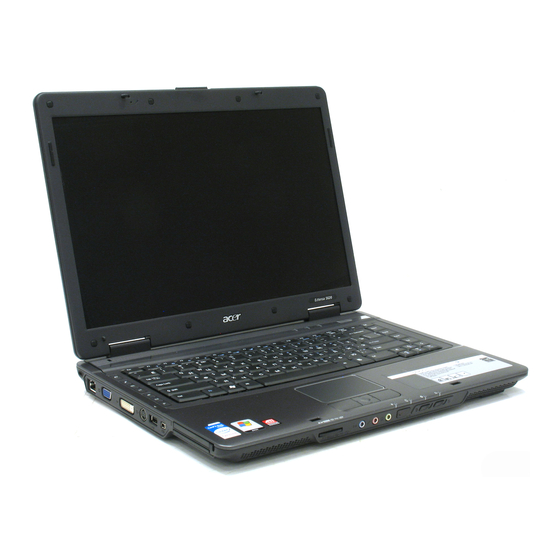
Outlook Tour Just for Starters... Just for Starters... "Launch keys" on page 10 Front View Aspire 9420/ 9410/ 7110 Series TravelMate 5620/ 5610/ 5110 Series Item Description "Launch keys" on page 10 Icon Item Description Icon Item Description Icon Item Description Icon Item... -
Page 17: Closed Front View
Item Description Item Description Icon Item Description Palmrest Comfortable support area for your hands when you use the computer. Item Description Keyboard For entering data into your computer. "Launch keys" on page 10 Power button Turns the computer on and off. Easy launch buttons Buttons for launching frequently used programs. -
Page 18: Left View
Icon Item Description Left View Aspire 9420/ 9410/ 7110 Series TravelMate 5620/ 5610/ 5110 Series Icon Item Description Icon Item Description Icon Item Description Icon Item Description Kensington lock slot Connects to a Kensington-compatible computers security lock. Icon Item Description Optical disk drive Internal optical drive;... -
Page 19: Rear View
Note: Rear View Aspire 9420/ 9410/ 7110 Series TravelMate 5620/ 5610/ 5110 Series Icon Item Description Icon Item Description Icon Item Description Icon Item Description Icon Item Description Icon Item Description USB 2.0 ports Connect to USB 2.0 devices (e.g., USB mouse, USB camera). Icon Item Description... -
Page 20: Base View
Houses the computer’s hard disk (secured with screws). Battery lock Locks the battery in position. Battery bay Houses the computer’s battery pack. Acer DASP (Disk Anti- Protects the hard disk drive from shocks and bumps. Shock Protection) (TravelMate 5620/ 5610/ 5110 series) Battery lock Locks the battery in position. -
Page 21: Windows Keys
"Acer eManager" on page 20 <Fn> + <F4> <Fn> + <F3> <Fn> + <F3> Fn + F3 Acer ePower Launches the Acer ePower Management in Acer page 20 Management Empowering Technology. <Fn> + <F3> <Fn> + <F4> <Fn> + <F3>... -
Page 22: Special Keys
<Fn> + <F5> <Fn> + <F6> <Fn> + <F7> <Fn> + <F6> <Fn> + <F6> <Fn> + <F7> <Fn> + <F6> Hot Key Icon Function Description <Fn> + <F7> <Fn> + <F7> <Fn> + <F7> Fn + F7 Touchpad toggle Turns the internal touchpad on and off. -
Page 23: Indicators
Indicators Item Description The computer provides an array of three indicators located above the keyboard, in addition to four indicators on the front cover. These indicators show the status of the computer and its components. Item Description Item Description "Launch keys" on page 10 "Launch keys"... -
Page 24: Easy-Launch Buttons
Acer Empowering Technology. Although the mail and web browser buttons are pre-set to E-mail and Internet programs, they can be redefined by users. To set the web browser, mail and programmable buttons, run the Acer Launch Manager. "Launch Manager" on page 44 "Easy-launch buttons"... -
Page 25: Touchpad
Touchpad The built-in touchpad is a pointing device that senses movement on its surface. This means the cursor responds as you move your finger across the surface of the touchpad. The central location on the palmrest provides optimum comfort and support. Touchpad Basics Use the touchpad as follows: •... -
Page 26: Acer Empowering Technology
Technology password. Right-click on the Empowering Technology tool bar and select Password Setup to do so. If you do not initialize the Empowering Technology password, you will be prompted to do so when running Acer eLock Management or Acer eRecovery Management for the first time. -
Page 27: Acer Edatasecurity Management
Acer eDataSecurity Management Acer eDataSecurity Management is a handy file encryption utility that protects the files from being accessed by unauthorized persons. It is conveniently integrated with Windows Explorer as a shell extension for quick and easy data encryption and decryption and also supports on-the-fly file encryption for MSN Messenger and Microsoft Outlook. - Page 28 Chapter 1...
-
Page 29: Acer Elock Management
Floppy disk drives: 3.5-inch disks only. To activate Acer eLock Management, a password must be set at first. Once set, you may apply locks to any of the three kinds of devices. The lock(s) will be set without any reboot necessary, and will remain locked after rebooting, until unlocked. -
Page 30: Acer Eperformance Management
Acer ePerformance Management Acer ePerformance Management is a system optimization tool that boosts the performance of the Acer notebook. It provides you with the following options to enhance overall system performance: • Memory optimization: releases unused memory and checks memory usage. -
Page 31: Acer Erecovery Management
Recovery from CD or DVD Note: If the computer did not come with a Recovery CD or System CD, please use Acer eRecovery Management’s “System backup to optical disk” feature to burn a backup image to CD or DVD. To ensure the best results when recovering the system using a CD or Acer eRecovery Management, detach all peripherals (except external Acer ODD, if equipped), including the Acer ezDock. -
Page 32: Acer Esettings Management
Acer eSettings Management Acer eSettings Management allows you to inspect hardware specification and to monitor the system health status. Furthermore, Acer eSettings Management enables you to optimize your Windows operating system, so your computer runs faster, smoother and better. •... -
Page 33: Acer Enet Management
Acer eNet Management Acer eNet Management helps you to quickly and easily connect to both wired and wireless networks in a variety of locations. To access this utility, either click on the “Acer eNet Management” icon on the notebook, or start the program from the Start menu. - Page 34 Chapter 1...
-
Page 35: Acer Epower Management
Acer ePower Management Acer ePower Management features a straightforward user interface. To launch it, select Acer ePower Management from the Empowering Technology interface, or double click the Acer ePower Management icon in the task tray. AC mode The default setting is “Maximum Performance.” You can adjust CPU speed, LCD brightness and other settings, or click on buttons to turn the following functions on or off: Wireless LAN, Bluetooth, CardBus, Memory Card, Audio, and Wired LAN. - Page 36 Chapter 1...
-
Page 37: Acer Epresentation Management
Acer ePresentation Management Acer ePresentation Management lets you select from two of the most common projector resolution: XGA and SVGA. Chapter 1... -
Page 38: Acer Orbicam
Launching the Acer OrbiCam (for 1.3 megapixel camera models only) To launch the Acer OrbiCam, double click on the Acer OrbiCam icon on the screen or Click Start > All programs > Acer > Acer OrbiCam. The Acer OrbiCam capture windows window appears as below:... -
Page 39: Changing The Acer Orbicam Settings
Changing the Acer OrbiCam Settings Resolution To change the capture resolution, click the displayed resolution at the bottom right corner of the capture window, then select the desired resolution. Note: Setting the camera resolution to 640 x 480 or larger does not change the capture window size. -
Page 40: Camera Settings
Options Window, Preview Folder Camera Settings • Basic settings: Click the Camera Settings icon on the bottom right corner of the capture display, then select Camera Settings from the pop-up menu. You can adjust the Video, Audio, and Zoom/Face tracking options from this window. Camera Settings Camera Settings Video, Audio... -
Page 41: Capturing Photos Or Videos
Capturing Photos or Videos To capture a photo or a video clip, rotate the Acer OrbiCam to get the desired angle, then click the Take a Picture or Record a Video button. The Windows Picture and Fax Viewer or the Windows Media Player automatically launches to display or play a preview of the photo/video clip. - Page 42 To Use the Face Tracking Feature 1. Click the left icon down arrow button, then select Single User or Multiple Users from the pop-up menu. For Single User Multiple multiple users, the face tracking feature automatically centers all the users’ face in the capture window, Users otherwise the utility centers the face of the user closest to the camera.
- Page 43 Note: When using avatars, you may have to calibrate the face points to achieve better tracking. Follow screen instructions in the VisageON to continue. Note: You may use video effects when using the camera for IM chat/video sessions or call conferences. Chapter 1...
-
Page 44: Using The System Utilities
Acer GridVista is a handy utility that offers four pre-defined display settings so you can view multiple windows on the same screen. To access this function, please go to Start > All Programs and click on Acer GridVista. You may... -
Page 45: Launch Manager
Note: Please ensure that the resolution setting of the second monitor is set to the manufacturer's recommended value. Note: Note: Launch Manager Launch Manager allows you to set the four easy-launch buttons located above the keyboard. You can access the "Easy-launch buttons"... -
Page 46: Norton Antivirus
Norton AntiVirus Norton AntiVirus is an anti-virus software that finds and repairs infected files, and protects against viruses to keep you computer data safe and secure. How do I check for viruses? A Full System Scan scans all files on your computer. To perform a system scan: Norton AntiVirus 1. -
Page 47: Hardware Specification And Configuration
Hardware Specification and Configuration Processor Item T7600 T7400 T7200 T5600 T5500 CPU speed (GHz) 2.33 2.16 1.83 1.66 Bus speed (MHz) Bus/Core Ratio L2 cache size (MB) L2 cache speed (GHz) 2.33 2.16 1.83 1.66 Package type (pin) 479/478 479/478 479/478 479/478 479/478... -
Page 48: Vga Interface
VGA Interface Item Discrete Chip 945GM/940GML Nvidia G72MV VRAM up to 128MB up to 256MB Card Reader Item Description PCMCIA controller TI7412 Card type support Type II Number of slot Feature Five-in-one Card Reader: Memory Stick (MS), Memory Stick Pro (MS PRO), MultiMediaCard (MMC), Secure Digital (SD) and xD-Picture Card (xD). -
Page 49: Power Management
Hotkey controls • Embedded numeric keypad • Multi-language support • Spill-proof • Four easy-launch buttons: Internet browser, E-mail with LED, Acer Empowering, one user-programmable button Battery Item Specification Vendor & model name Panasonic / Sanyo / Sony Battery Type Li-Ion... -
Page 50: Lcd Panel
LCD Panel Item Specification Model name SAMSUNG B170PW03 V3 QD17TL02-06 LTN170WX-L05-1 LP171WP4-TL02 B170PW03 V4 LTN170WX-L05-H Screen Diagonal 17.1” WXGA 17.1” WXGA 17.1” WXGA 17.1” WXGA (mm) Active Area (mm) 367.20 (W) x 367.20 (W) x 367.20 (W) x 367.20 (W) x 229.50 (H) 229.50(H) 229.50(H) -
Page 51: Hard Disk Drive
AC Adaptor Item Specification Model name LiteOn PA-1900-04AW Delta 90W ADP-90SB BBAA Input feature Rated voltage for 100Vac or 240Vac input AC for 100Vac or 240Vac input AC voltage voltage Input voltage range from 90Vac to 264Vac from 90Vac to 265Vac Rated frequency for 50Hz or 60Hz for 50Hz or 60Hz... - Page 52 Seagate Average seek, 14.5 write (msec. typical) Cache buffer 8 Mbytes Interface Serial ATA Startup current +5V: 1.1 amps (typical, peak) Ambient 5 to 55 C (operating), -40 to 70 C (nonoperating) temperature Temperature C (operating), 30 C (nonoperating) gradient ( C per hour max.) Relative humidity...
- Page 53 24X Combo Drive Interface Item Specification Model PHILIPS SCB5265 LITEON SSC-2485K Performance Specification Transfer rate (KB/sec.) Sustained: Sustained: • • DVD: Max 10.56Mbytes/sec. DVD: Min 10.15Mbytes/sec. • • CD: 3600Kbytes/sec. CD: 3500 Kbytes/sec. • • Access Time (Typical) DVD: Random Access: 125 ms DVD: Random Access: 100 ms •...
- Page 54 8X DVD Dual Interface Item Specification Vendor and model name PHILIPS SDVD8441 Performance specification Transfer rate (KB/sec.) Sustained: • DVD:10.9Mbytes/sec. (Typ) • CD: 3650Kbytes/sec. (Typ) • Access time (typical) DVD: Random Access: 130 ms • DVD: Full Stroke: 240ms • CD: Random Access:130ms •...
- Page 55 8X Super Multi (DL) Item Specification Vendor and model name Liteon SSM 8515S Pioneer DVR-K06RS Philip SDVD-8821 Performance Specification Transfer rate read (KB/sec.) Sustained: Sustained: Sustained: • • • DVD: 10.00Mbytes/ DVD: 10.80Mbytes/ DVD: 10.90Mbytes/ sec. sec. sec. • • •...
-
Page 56: Chapter Two System Utilities
Chapter 2 System Utilities BIOS Setup Utility The BIOS Setup Utility is a hardware configuration program built in the BIOS (Basic Input / Output System) of computer. Generally speaking, the computer is already properly configured and optimized, and you do not need to run this utility. -
Page 57: Information
Information • CPU type: This item will show the CPU information of the system. • CPU speed: This item will show the COU clock speed. • IDE1 model name: This item will show the model name of HDD installed on primary IDE master. The hard disk model name is automatically detected by the system. -
Page 58: Main
Main • System Time and System Date: The hours are displayed with 24-hour format. The changes in these two items take effect immediately. • System Memory: This item reports the memory size of system base memory. The size is fixed to 640KB. •... - Page 59 device sequence will be the same as the one defined in the BIOS setup (Boot option). • D2D Recovery: It allows the users to enable or disable the disk-to-disk recovery. Chapter 2...
-
Page 60: Security
Security The system supports three levels of password protection. The password support consists of a Supervisor Password, User Password, and Hard Disk Password. All the passwords are stored in a non-volatile storage device (EEPROM). • Password Policy: All the passwords will obey the following rules: •... - Page 61 Symbol Character Symbol Name slash back slash • The users can not change or remove password during resuming from S4. • The max. number of times to retry the password is limited to three. • Supervisor Password: Supervisor Password controls the access of the whole BIOS Setup Utility. If the Supervisor Password is set, the system will pop up the password dialog box to ask for the password when the users press <F2>...
-
Page 62: Boot
Boot This menu allows the users to decide the order of bootable devices to load the operating system. It identifies all the bootable devices in the system and attempts to boot them in the order specified. Bootable devices include the diskette drive in module bay, the hard disk and the CD-ROM/DVD drive in module bay and onboard LAN device. -
Page 63: Exit
Exit • Exit Saving Changes: It allows the users to save changes to CMOS and reboot the system. • Exit Discarding Changes: The users can exit the Setup not to save changes. • Load Setup Defaults: It allows the users to load default values in CMOS Setup. •... -
Page 64: Chapter Three Machine Disassembly And Replacement
Chapter 3 Machine Disassembly and Replacement This chapter contains step-by-step procedures on how to disassemble the notebook for maintenance and troubleshooting. To disassemble the computer, you need the tools below: • Wrist ground strap and conductive mat for preventing electrostatic discharge •... -
Page 65: General Information
General Information Before You Begin Before proceeding with the disassembly procedure, you have to make sure that: 1. The system and all peripherals are powered off. 2. The AC adaptor and all power and signal cables from the system are unplugged. 3. -
Page 66: Disassembly Procedure Flowchart
Disassembly Procedure Flowchart The flowchart gives you a graphic representation on the entire disassembly and reassembly and instructs you how to remove the components. Description Part No. SCW HEX NYL I#R-40/O#4-40 L5.5 34.00015.081 SCREW MACH WAFER M2*L4 NI 86.T39V1.002 SCRW M2.5*6 ~ L-CASE + U-CASE 86.00D28.330 SCRW M2*L3 86.00D29.620... - Page 67 Description Part No. SCREW M2.5*L8 NYLOK CR3+ 86.00E34.738 SCREW M2*L8 NI NON-NYLOK 86.00E35.228 SCREW M3x4(86.9A524.4R0) 86.9A524.4R0 SCRW M2*4 WAFER NI 86.9A552.4R0 SCREW NI M2*6L 86.9A552.6R0 SCRW M2.5*L3(NON NYLOK) 86.9A523.3R0 Chapter 3...
-
Page 68: Disassembly Procedure
Disassembly Procedure Removing the Battery Pack 1. Unlock the battery pack. 2. Slide the battery latch, hold it then remove the battery. Removing the HDD Module 1. Release the three screws fastening the HDD module cover. 2. Detach the HDD module cover. 3. -
Page 69: Removing The Minipci Card And The Memory
Removing the MiniPCI Card and the Memory 1. Release the two screws securing the miniPCI cover. 2. Remove the miniPCI cover. 3. Disconnect the wireless antenna then remove the wireless LAN card. 4. Release the two screws securing the RAM cover and remove the RAM cover. 5. - Page 70 5. Remove the keyboard and reverse it. 6. Carefully pull the keyboard FFC lock, then disconnect the keyboard FFC. Chapter 3...
-
Page 71: Separating The Lcd Module And Main Unit
Separating the LCD Module and Main Unit 1. Pull carefully and disconnect the LCD cable. 2. Tear off the tape securing the wireless antenna and pull out the wireless antenna. 3. Release the two screws securing the LCD hinges on the bottom side. 4. -
Page 72: Disassembling The Main Unit
Disassembling the Main Unit Separating the Upper Case and the Lower Case 1. Release the connector lock and disconnect the touch pad FFC. 2. Release the connector lock and disconnect the function keyboard FFC. 3. Release the three screws securing the upper case. 4. - Page 73 Removing the Function Keyboard 1. Release the FFC lock and disconnect the function keyboard FFC. 2. Release the four screws holding the function keyboard bracket. 3. Then remove the function keyboard bracket. 4. Carefully disconnect the microphone cable and remove the function keyboard. Chapter 3...
- Page 74 Removing the Touch Pad Board 1. Carefully release the FFC lock and disconnect the touch pad board FFC. 2. There are 13 latches holding the touch pad bracket. 3. Unlock those latches with a screw driver as shown then detach the touch pad bracket. 4.
- Page 75 Removing the ODD Module and Dummy Card 1. Slightly pull the ODD module and remove it. 2. Pull the dummy card from the slot and remove it. Removing the Main Board 1. Disconnect the fan cable. 2. Disconnect the speaker cable and Bluetooth module cable. 3.
- Page 76 Removing the System Fan 1. Release the two screws holding the heatsink. 2. Remove the heatsink. Removing the Bluetooth Module 1. Detach the bluetooth module from the lower case. 2. Carefully disconnect the bluetooth module cable. Removing the Speakers 1. Release the four screws securing the left and right speakers. 2.
- Page 77 Removing the MDC Module 1. Carefully disconnect the MDC cable. 2. Release the two screws securing the MDC board then detach the MDC board. 3. Disconnect the MDC board cable. Remove the Heatsink Module 1. Release the five screws securing the heatsink. 2.
-
Page 78: Lcd Disassembly
Removing the CPU 1. Release the screw counter clockwise with a flat screw driver. 2. Detach the CPU from the CPU socket. LCD Disassembly 1. Remove the eight rubber caps on the LCD bezel and release the eight screws securing the LCD bezel. 2. - Page 79 5. Release the four screws securing the LCD panel. 6. Detach the LCD panel carefully and reverse it as shown. 7. Tear off the tapes holding the LCD panel cable carefully then disconnect the LCD panel. 8. Remove the antenna from the LCD cover. Chapter 3...
- Page 80 9. Release the four screws securing the left LCD bracket then remove the left LCD bracket. 10. Repeat the anterior step to remove the right LCD bracket. Chapter 3...
- Page 81 11. Release the screw holding the CCD module and carefully pull the CCD module cable and LCD cable through the latch bar and LCD cover. 12. Remove the CCD module cap. 13. Remove the CCD module ring. 14. Push the CCD module upper case a little bit. 15.
-
Page 82: Chapter Four Troubleshooting
Troubleshooting Please use the following procedures as a guide for computer problems. Note: The diagnostic tests are intended to test only Acer products. Non-Acer products, prototype cards, or modified options may occur errors or invalid responses. 1. Obtain the detailed fail symptoms as many as possible. -
Page 83: System Check Procedures
System Check Procedures External Diskette Drive Check Do the following procedures to isolate the possible effects from a controller, driver, or diskette. A writable, diagnostic diskette is required. Note: Make sure that the diskette does not have more than one label attached. Multiple labels may cause damage to the drive or make the drive fail. -
Page 84: Power System Check
2. Go to the diagnostic memory in the test items. 3. Press F2 in the test items. 4. Follow the instructions in the message window. Note: Make sure that the DIMM is correctly inserted into the connector. A wrong connection will cause errors. Power System Check To verify the symptoms, power on the computer by using the following power sources separately. -
Page 85: Touchpad Check
If the charge indicator does not light up, replace the battery pack. If the charge indicator still does not light up, replace the AC/DC charger board. Touchpad Check If the touchpad does not work, follow the procedures one at a time to correct the problem. Do not replace a non- defective FRU. -
Page 86: Power-On Self-Test (Post) Error Message
Power-On Self-Test (POST) Error Message The POST error message index lists the error message and their possible causes. Note: Perform the FRU replacement or actions in the sequence shown in Error Message List, if the FRU replacement does not solve the problem, put the original part back in the computer. Do not replace a non- defective FRU. -
Page 87: Index Of Error Messages
Index of Error Messages Error Message List Error Messages FRU/Action in Sequence Struck Key See “Keyboard or Auxiliary Input Device Check“. System CMOS checksum bad - RTC battery Default configuration used Run BIOS Setup Utility to reconfigure system, then reboot system. Real time clock error RTC battery Run BIOS Setup Utility to reconfigure system time, then... -
Page 88: Phoenix Bios Beep Codes
Phoenix BIOS Beep Codes Code Beeps POST Routine Description Verify Real Mode Disable Non-Maskable Interrupt (NMI) Get CPU type Initialize system hardware Disable shadow and execute code from the ROM. Initialize chipset with initial POST values Set IN POST flag Initialize CPU registers Enable CPU cache Initialize caches to initial POST values... - Page 89 Code Beeps POST Routine Description Autosize cache Advanced configuration of chipset registers Load alternate registers with CMOS values Initialize extended memory for RomPilot. Initialize interrupt vectors POST device initialization 2-1-2-3 Check ROM copyright notice Initialize I20 support Check video configuration against CMOS Initialize PCI bus and devices Initialize all video adapters in system...
- Page 90 Code Beeps POST Routine Description Set up hardware interrupt vectors Initialize coprocessor if present Disable onboard Super I/O ports and IRQs Late POST device initialization Detect and install external RS232 ports Configure non-MCD IDE controllers Detect and install external parallel ports Initialize PC-compatible PnP ISA devices Re-initialize onboard I/O ports...
- Page 91 Code Beeps POST Routine Description Inform RomPilot about the end of POST. POST done- prepare to boot operating system One short beep before boot Terminate QuietBoot (optional) Check password (optional) Initialize ACPI BIOS Prepare Boot Initialize SMBIOS Initialize PnP Option ROMs Clear parity checkers Display MultiBoot menu Clear screen (optional)
- Page 92 Code Beeps POST Routine Description Initialize Multi Processor Initialize OEM special code Initialize PIC and DMA Initialize Memory type Initialize Memory size Shadow Boot Block System memory test Initialize interrupt vectors Initialize Run Time Clock Initialize video Initialize System Management Mode Output one beep Clear Huge Segment Boot to Mini DOS...
-
Page 93: Index Of Symptom-To-Fru Error Message
Index of Symptom-to-FRU Error Message Symptom/Error Action in Sequence LCD backlight doesn't work. Enter BIOS Utility to execute “Load Setup Default Settings”, then reboot system. LCD is too dark. Reconnect the LCD connectors. LCD brightness cannot be adjusted. Keyboard (if contrast and brightness function key do LCD contrast cannot be adjusted. - Page 94 Symptom/Error Action in Sequence System cannot detect the PCMCIA slot assembly PC Card (PCMCIA). System board PCMCIA slot pin is PCMCIA slot assembly damaged. Symptom / Error Action in Sequence Memory count (size) Enter BIOS Setup Utility to execute “Load Default Settings, appears different from then reboot system.
- Page 95 Symptom/Error Action in Sequence System configuration Enter BIOS Setup Utility to execute “Load Default Settings”, does not match the then reboot system. installed devices. Reconnect hard disk/CD-ROM/diskette drives. External display does not Press Fn + F5, LCD/CRT/Both display switching work correctly. System board USB does not work System board...
-
Page 96: Intermittent Problems
Intermittent Problems Intermittent system hang problems can be caused by a variety of reasons that have nothing to do with a hardware defect, such as cosmic radiation, electrostatic discharge, or software errors. FRU replacement should be considered only when a recurring problem exists. When analyzing an intermittent problems, follow the procedures below: 1. -
Page 97: Undetermined Problems
1. Power off the computer. 2. Visually check the devices. If any problems are found, replace the FRU. 3. Remove or disconnect all of the following devices: • Non-Acer devices • Printer, mouse, and other external devices • Battery Pack •... -
Page 98: Chapter Five Jumper And Connector Location
Chapter 5 Jumper and Connector Location Top View Description Description DC-in jack USB connector CRT connector RJ11 & RJ45 connector MDC module connector MDC board connector Main battery connector ODD connector Mini PCI slot North bridge DIMM slot South bridge HDD connector Line-in jack Microphone-in jack... - Page 99 Description Description Line-out jack Cardbus controller USB connector LAN controller BIOS ROM RTC battery connector 5-in-1 card reader Chapter 5...
-
Page 100: Bottom View
Bottom View Item Description Item Description Keyboard controller Keyboard connector Lid switch connector System fan connector PCMCIA card reader Function key board connector Touch pad board connector Speaker connector Bluetooth module connector LCD cable connector Chapter 5... -
Page 101: Chapter Six Fru (Field Replaceable Unit) List
Acer office to order FRU parts for service. Note: To scrap or to return the defective parts, you should follow the local government ordinance or regulations on how to dispose them properly, or follow the rules set by your regional Acer office on how to return it. -
Page 102: Exploded Diagram
Exploded Diagram Chapter 6... -
Page 103: Parts
Parts Aspire 9410 UMA ACER PART CATEGORY PART NAME DESCRIPTION ADAPTER ADAPTER 90W LITEON PA- ADT 90W LITEON PA- AP.09003.005 1900-04WR 1900-04WR ADAPTER 90W DELTA ADP- ADT 90W DELTA ADP- AP.09001.004 90SB BBAAF 90SB BBAAF BATTERY RTC BATTERY BTY RTC MITSUBISHI 23.TCBV1.003... - Page 104 ACER PART CATEGORY PART NAME DESCRIPTION WIRELESS LAN BOARD WLAN 802.11ABG KI.GLN01.003 802.11ABG INTEL 3945 RW INTEL 3945 RW WIRELESS LAN BOARD WLAN 802.11ABG KI.GLN01.002 802.11ABG INTEL 3945 MW2 INTEL 3945 MW2 WIRELESS LAN BOARD WLAN 802.11ABG KI.GLN01.001 802.11ABG INTEL 3945 MW1...
- Page 105 ACER PART CATEGORY PART NAME DESCRIPTION POWER CORD 10A 250V CORD 10A 250V 3P 27.01518.711? 3PIN ITALY ITALY BK POWER CORD 10A 250V CORD ITALY 10A 27.01518.611 3PIN ITALY 250V 3P BK POWER CORD 10A 250V CODE 10A 250V 3P 27.01518.691...
- Page 106 ACER PART CATEGORY PART NAME DESCRIPTION MIDDLE COVER ASSY MIDDLE 60.ACKV1.003 COVER--AS MYALL MINI PCI COVER ASSY MINIPCI 42.TCBV1.003 COVER MYALL MINI CARD COVER ASSY MINICARD 42.TCBV1.004 COVER MYALL HDD COVER ASSY HDD COVER 42.ACKV1.001 MYALL DIMM COVER ASSY DIMM COVER 42.TCBV1.002...
- Page 107 ACER PART CATEGORY PART NAME DESCRIPTION DVD DUAL BEZEL ASSY DVD_DUAL 42.TCBV1.012 ODD BEZEL DVD SUPER MULIA BEZEL ASSY S_MULTI ODD 42.TCBV1.013 BEZEL GBASE DVD SUPER MULIA BEZEL ASSY ODD SLOT-IN 42.TCBV1.014 BEZEL HDD CHASSIS ASSY HDD CHASSIS 33.TCBV1.003 MYALL "LCD PANEL 17.1""...
- Page 108 ACER PART CATEGORY PART NAME DESCRIPTION COMBO MODULE 24X ASSY ODD COMBO 6M.ADFV1.001 MYALL2 CDRW/DVD COMBO DRIVE COMBO PHI/SCB5265 KO.02408.010 24X PHILIPS SCB5265 W/O MYALL NOBZL BEZEL CDRW/DVD COMBO DRIVE COMBO LIT/SOSC- KO.02409.022 24X LITEON SOSC-2485K 2485K NO BZL W/O BEZEL...
- Page 109 ACER PART CATEGORY PART NAME DESCRIPTION CPU DC YONAH T2300 IC CPU DC YONAH KC.23001.DTP 1.66GMHZ INTEL T2300 1.66G PGA CPU DC YONAH T2600 IC CPU DC YONAH KC.26001.DTP 2.17GMHZ INTEL T2600 2.17G PGA CPU DC YONAH T2500 IC CPU DC YONAH KC.25001.DTP...
- Page 110 ACER PART CATEGORY PART NAME DESCRIPTION HDD 60G 4200RPM HDD 60GB SEAGATE KH.06001.006 SEAGATE ST960812A ST960812A HDD 60G HITACHI HDD 60GB HGST KH.06007.009 HTS421260H9AT00 HTS421260H9AT00 HDD 60G 4200RPM HDD 60GB TOSHIBA KH.06004.004 TOSHIBA MK6025GAS MK6025GAS HDD 60G 5400RPM HDD 60GB SEAGATE KH.06001.007...
- Page 111 ACER PART CATEGORY PART NAME DESCRIPTION HDD 120G 4200RPM HDD 120GB HGST KH.12007.006 HITACHI 0A26308 0A26308 ROHS HDD 120G 5400RPM HDD 120GB KH.12001.024 SEAGATE ST9120821A SEAGATE ST9120821A HDD 120G 5400RPM HDD 120GB TOSHIBA KH.12004.002 TOSHIBA 5400RPM HDD 160G 5400RPM HDD 160GB KH.12001.024...
- Page 112 ACER PART CATEGORY PART NAME DESCRIPTION AS9400/7100 KEYBOARD AS9400/7100 KB.ACF07.011 DARFON SWISS/G KEYBOARD DARFON SWISS/G AS9400/7100 KEYBOARD AS9400/7100 KB.ACF07.012 DARFON PORTUGUESE KEYBOARD DARFON PORTUGUESE AS9400/7100 KEYBOARD AS9400/7100 KB.ACF07.013 DARFON ARABIC KEYBOARD DARFON ARABIC AS9400/7100 KEYBOARD AS9400/7100 KB.ACF07.014 DARFON BELGIUM KEYBOARD DARFON...
- Page 113 ACER PART CATEGORY PART NAME DESCRIPTION "LCD 17"" WXGA+ LG "LCD 17""W LK.17008.015 LP171WP4-TL02 GLARE" LP171WP4-TL02 GLARE" "LCD 17.1"" WXGA+ QDI "LCD 17""W QDI LK.17109.001 QD17TL02-05 NONE GLARE QD17TL02-05" " "LCD 17""WXGA+ QDI "LCD 17"" QD17TL02- LK.17109.002 QD17TL02-06 GLARE" 06 GLARE"...
- Page 114 LCD SCREW RUBBER RUBBER SCREW 47.TCBV1.001 MYALL MISCELLANEOUS LOGO PLATE FOR PANEL PLT LOGO PANEL 31.T49V1.001 MISCELLANEOUS LOGO PLATE FOR BEZEL "PLT BEZEL PLATE 31.A46V1.001 ""ACER "" LOGO " SCREW SCREW SCW HEX NYL I#R- 34.00015.081 40/O#4-40 L5.5 Chapter 6...
- Page 115 ACER PART CATEGORY PART NAME DESCRIPTION SCREW SCREW MACH 86.T39V1.002 WAFER M2*L4 NI SCREW SCRW M2.5*6 ~ L- 86.00D28.330 CASE + U-CASE SCREW SCRW M2*L3 86.00D29.620 SCREW SCRW M2.5*5 WAFER 86.00D47.630 B-ZN ROHS SCREW SCREW M2*L3 86.00E25.723 NYLOK CR 3+...
Need help?
Do you have a question about the Aspire 9420/ 9410/ 7110 TravelMate 5620/ 5610/ 5110 and is the answer not in the manual?
Questions and answers