ASROCK FM2A85X Extreme6 User Manual
User manual
Hide thumbs
Also See for FM2A85X Extreme6:
- Installation manual (26 pages) ,
- Quick installation manual (186 pages)

Related Manuals for ASROCK FM2A85X Extreme6


Summary of Contents for ASROCK FM2A85X Extreme6
-
Page 1: User Manual
FM2A85X Extreme6 User Manual Version 1.0 Published September 2012 Copyright©2012 ASRock INC. All rights reserved. -
Page 2: Copyright Notice
ASRock. ASRock assumes no responsibility for any errors or omissions that may appear in this manual. With respect to the contents of this manual, ASRock does not provide warranty of any kind, either expressed or implied, including but not limited to the implied warran- ties or conditions of merchantability or fitness for a particular purpose. -
Page 3: Table Of Contents
Quad CrossFireX Operation Guide ................ 22 Dual Graphics Operation Guide ..........27 Multi Monitor and Surround Display Features ......29 ASRock Smart Remote Installation Guide ......... 32 Jumpers Setup ................34 2.10 Onboard Headers and Connectors ........35 2.11 Smart Switches ................40 2.12 Dr. - Page 4 3. UEFI SETUP UTILITY ..........47 Introduction ................47 3.1.1 UEFI Menu Bar ..............47 3.1.2 Navigation Keys ............... 48 Main Screen ................48 OC Tweaker Screen..............49 Advanced Screen ..............52 3.4.1 CPU Configuration ............53 3.4.2 North Bridge Configuration ..........54 3.4.3 South Bridge Configuration ..........
-
Page 5: Introduction
In case any modifications of this manual occur, the updated ver- sion will be available on ASRock website without further notice. You may find the latest VGA cards and CPU support lists on ASRock website as well. ASRock website http://www.asrock.com... -
Page 6: Specifications
1.2 Specifications Platform - ATX Form Factor - Premium Gold Capacitor design (100% Japan-made high-quality Conductive Polymer Capacitors) CPU - Support for Socket FM2 100W processors - Digi Power Design - 8 + 2 Power Phase Design - Supports AMD’s Cool ‘n’ Quiet Technology - UMI-Link GEN2 Chipset - AMD A85X (Hudson-D4) Memory - Dual Channel DDR3 Memory Technology - 4 x DDR3 DIMM slots - Support DDR3 2600+(OC)/2400(OC)/2133(OC)/1866/1600/ 1333/1066/800 non-ECC, un-buffered memory (see CAUTION 1) * 2600+ is only supported with two DIMMs - Max. capacity of system memory: 32GB (see CAUTION 2) ® - Supports Intel Extreme Memory Profile (XMP) 1.3 / 1.2 - Supports AMD Memory Profile (AMP) Expansion Slot - 3 x PCI Express 2.0 x16 slots (PCIE2/PCIE4: single at x16 (PCIE2) / x8 (PCIE4), or dual at x8 (PCIE2) / x8 (PCIE4) ; PCIE5: x4 mode) - 2 x PCI Express 2.0 x1 slots - 2 x PCI slots - Supports AMD Quad CrossFireX , 3-Way CrossFireX CrossFireX and Dual Graphics Graphics - AMD Radeon HD 7000 graphics - DirectX 11, Pixel Shader 5.0... - Page 7 - Supports Multi-Streaming - Supports Auto Lip Sync, Deep Color (12bpc), xvYCC and HBR (High Bit Rate Audio) with HDMI (Compliant HDMI monitor is required) (see CAUTION 4) - Supports Blu-ray Stereoscopic 3D with HDMI 1.4a - Supports AMD Steady Video 2.0: New video post processing capability for automatic jutter reduction on home/ online video - Supports HDCP function with DVI, HDMI and DisplayPort ports - Supports Full HD 1080p Blu-ray (BD) / HD-DVD playback with DVI, HDMI and DisplayPort ports Audio - 7.1 CH HD Audio with Content Protection (Realtek ALC898 Audio Codec) - Premium Blu-ray audio support - Supports THX TruStudio - PCIE x1 Gigabit LAN 10/100/1000 Mb/s - Realtek RTL8111E - Supports Wake-On-LAN - Supports LAN Cable Detection - Supports Energy Efficient Ethernet 802.3az - Supports PXE Rear Panel I/O I/O Panel - 1 x PS/2 Mouse/Keyboard Port - 1 x D-Sub Port - 1 x DVI-D Port - 1 x HDMI Port - 1 x DisplayPort - 1 x Optical SPDIF Out Port - 2 x Ready-to-Use USB 2.0 Ports - 1 x eSATA3 Connector - 4 x Ready-to-Use USB 3.0 Ports - 1 x RJ-45 LAN Port with LED (ACT/LINK LED and SPEED LED) - 1 x Clear CMOS Switch with LED - HD Audio Jack: Rear Speaker/Central/Bass/Line in/Front Speaker/Microphone...
- Page 8 - DRAM, APU PCIE VDDP, CPU and CPU NB/GFX Voltage Multi-adjustment Support CD - Drivers, Utilities, AntiVirus Software (Trial Version), AMD Live! Explorer, AMD Fusion, CyberLink MediaEspresso 6.5 Trial, ASRock MAGIX Multimedia Suite - OEM, Google Chrome Browser and Toolbar Hardware - CPU Temperature Sensing Monitor...
- Page 9 ® der Windows 8 / 7 / Vista . For Windows 64-bit OS with 64- bit CPU, there is no such limitation. You can use ASRock XFast ® RAM to utilize the memory that Windows cannot use. 3. You can choose to use three of the four monitors only. D-Sub, DVI-D, HDMI and DisplayPort monitors cannot be enabled at the same time.
-
Page 10: Unique Features
OS 32-bit CPU. ASRock Instant Boot ASRock Instant Boot allows you to turn on your PC in just a few seconds, provides a much more efficient way to save energy, time, money, and improves system running speed for your sys- tem. - Page 11 ASRock XFast RAM ASRock XFast RAM is a new function that is included into AS- Rock Extreme Tuning Utility (AXTU). It fully utilizes the memory ® space that cannot be used under Windows OS 32-bit CPU.
- Page 12 S4/S5 state. ASRock Easy RAID Installer ASRock Easy RAID Installer can help you to copy the RAID driver from a support CD to your USB storage device. After copying the RAID driver to your USB storage device, please change “SATA Mode”...
- Page 13 UEFI setup. AS- Rock Restart to UEFI technology is designed for those requiring frequent UEFI access. It is included in ASRock’s exclusive all- in-one AXTU tuning program that allows users to easily enter the UEFI automatically when turning on the PC next time.
-
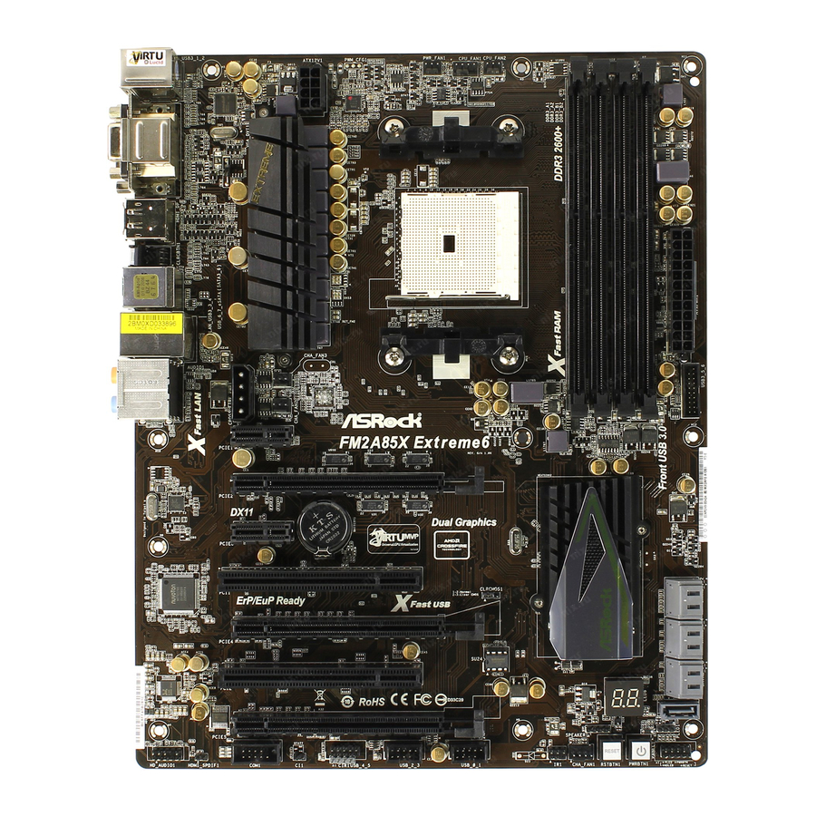
Page 14: Motherboard Layout
/Mouse ATX12V1 CMOS USB 2.0 T: USB6 B: USB7 USB 3.0 Top: T: USB3 RJ-45 B: USB4 CROSS_FIRE_PWR1 CHA_FAN3 CHA_FAN2 PCIE1 FM2A85X Extreme6 PCIE2 DX11 Dual Graphics CMOS PCIE3 BATTERY A85X (Hudson-D4) PCI1 Chipset CLRCMOS1 ErP/EuP Ready Fast USB PCIE4... -
Page 15: I/O Panel
1.5 I/O Panel PS/2 Mouse/Keyboard Port (Green/Purple) *** 10 Front Speaker (Lime) D-Sub Port (VGA1) Microphone (Pink) DisplayPort (DP_1) USB 3.0 Ports (USB3_3_4) USB 2.0 Ports (USB_6_7) **** 13 eSATA3 Connector (SATA3_6) ** 5 LAN RJ-45 Port Clear CMOS Switch (CLRCBTN) Central / Bass (Orange) HDMI Port (HDMI1) Rear Speaker (Black) - Page 16 To enable Multi-Streaming function, you need to connect a front panel audio cable to the front panel audio header. After restarting your computer, you will find “Mixer” tool on your system. Please select “Mixer ToolBox” , click “Enable playback multi-streaming”, and click “ok”. Choose “2CH”, “4CH”, “6CH”, or “8CH”...
-
Page 17: Installation
2. Installation This is an ATX form factor motherboard. Before you install the motherboard, study the configuration of your chassis to ensure that the motherboard fits into it. Pre-installation Precautions Take note of the following precautions before you install motherboard components or change any motherboard settings. -
Page 18: Cpu Installation
2.1 CPU Installation Step 1. Unlock the socket by lifting the lever up to a 90 angle. Step 2. Position the CPU directly above the socket such that the CPU corner with the golden triangle matches the socket corner with a small triangle. Step 3. -
Page 19: Installation Of Memory Modules (Dimm)
2.3 Installation of Memory Modules (DIMM) This motherboard provides four 240-pin DDR3 (Double Data Rate 3) DIMM slots, and supports Dual Channel Memory Technology. For dual channel con- figuration, you always need to install identical (the same brand, speed, size and chip-type) DDR3 DIMM pair in the slots of the same color. -
Page 20: Installing A Dimm
Installing a DIMM Please make sure to disconnect power supply before adding or removing DIMMs or the system components. Step 1. Unlock a DIMM slot by pressing the retaining clips outward. Step 2. Align a DIMM on the slot such that the notch on the DIMM matches the break on the slot. -
Page 21: Expansion Slots (Pci And Pci Express Slots)
2.4 Expansion Slots (PCI and PCI Express Slots) There are 2 PCI slots and 5 PCI Express slots on this motherboard. PCI Slots: PCI slots are used to install expansion cards that have the 32-bit PCI interface. PCIE Slots: PCIE1 / PCIE3 (PCIE x1 slot) is used for PCI Express cards with x1 lane width cards, such as Gigabit LAN card and SATA2 card. -
Page 22: Crossfirex Tm , 3-Way Crossfirex
CrossFireX , 3-Way CrossFireX and Quad CrossFireX Operation Guide This motherboard supports CrossFireX , 3-way CrossFireX and Quad CrossFireX feature. CrossFireX technology offers the most advantageous means available of combining multiple high performance Graphics Processing Units (GPU) in a single PC. Combining a range of different operating modes with intelligent software design and an innovative interconnect mechanism, CrossFireX enables the highest possible level of performance and image quality in any 3D application. - Page 23 Step 2. Connect two Radeon graphics cards by installing CrossFire Bridge on CrossFire Bridge Interconnects on the top of Radeon graphics cards. (CrossFire Bridge is provided with the graphics card you purchase, not bundled with this motherboard. Please refer to your graphics card vendor for details.) CrossFire Bridge Step 3.
-
Page 24: Installing Three Crossfirex
2.5.1.2 Installing Three CrossFireX -Ready Graphics Cards Step 1. Install the identical 3-Way CrossFireX -ready graphics cards that are AMD certified because different types of graphics cards will not work to- gether properly. (Even the GPU chips version shall be the same.) Insert one graphics card into PCIE2 slot, another graphics card to PCIE4 slot, and the other graphics card to PCIE5 slot. -
Page 25: Driver Installation And Setup
2.5.2 Driver Installation and Setup Step 1. Power on your computer and boot into OS. Step 2. Remove the ATI driver if you have any VGA driver installed in your system. The Catalyst Uninstaller is an optional download. We recommend using this utility to uninstall any previously installed Catalyst drivers prior to installation. -
Page 26: Tm Tm Tm
Although you have selected the option “Enable CrossFire ”, the CrossFireX function may not work actually. Your computer will automatically reboot. After restarting your computer, please confirm whether the option “Enable CrossFire ” in “ATI Catalyst Control Center” is selected or not; if not, please select it again, and then you are able to enjoy the benefit of CrossFireX feature. -
Page 27: Dual Graphics Operation Guide
2.6 AMD Dual Graphics Operation Guide This motherboard supports AMD Dual Graphics feature. AMD Dual Graphics brings multi-GPU performance capabilities by enabling an AMD A85X (Hudson-D4) integrated graphics processor and a discrete graphics processor to operate simultaneously with combined output to a single display for blisteringly-fast frame ®... - Page 28 Step 7. You can also click “AMD VISION Engine Control Center” on your ® Windows taskbar to enter AMD VISION Engine Control Center. AMD VISION Engine Control Center Step 8. In AMD VISION Engine Control Center, please choose “Performance”. Click “AMD CrossFire ”.
-
Page 29: Multi Monitor And Surround Display Features
2.7 Multi Monitor and Surround Display Features Multi Monitor Feature This motherboard supports multi monitor feature. With the internal VGA output sup- port (DVI-D, D-Sub, HDMI and DisplayPort), you can easily enjoy the benefits of multi monitor feature without installing any add-on VGA card to this motherboard. This motherboard also provides independent display controllers for DVI-D, D-Sub, HDMI and DisplayPort to support multi VGA output so that DVI-D, D-sub, HDMI and DisplayPort can drive same or different display contents. - Page 30 Surround Display Feature This motherboard supports surround display upgrade. With the internal VGA output support (DVI-D, D-Sub, HDMI and DisplayPort) and external add-on PCI Express VGA cards, you can easily enjoy the benefits of surround display feature. Please refer to the following steps to set up a surround display environment: 1.
- Page 31 HDCP Function HDCP function is supported on this motherboard. To use HDCP function with this motherboard, you need to adopt the monitor that supports HDCP function as well. Therefore, you can enjoy the superior display quality with high-definition HDCP encryption contents. Please refer to below instruction for more details about HDCP function.
-
Page 32: Asrock Smart Remote Installation Guide
2.8 ASRock Smart Remote Installation Guide ASRock Smart Remote is only used for ASRock motherboard with CIR header. Please refer to below procedures for the quick installation and usage of ASRock Smart Remote. Step1. Find the CIR header located next to the USB 2.0 header on ASRock... - Page 33 The Multi-Angle CIR Receiver does not support Hot-Plug function. Please install it before you boot the system. * ASRock Smart Remote is only supported by some of ASRock motherboards. Please refer to ASRock website for the motherboard support list: http://www.asrock.com...
-
Page 34: Jumpers Setup
2.9 Jumpers Setup The illustration shows how jumpers are setup. When the jumper cap is placed on pins, the jumper is “Short”. If no jumper cap is placed on pins, the jumper is “Open”. The illustration shows a 3-pin jumper whose pin1 and pin2 are “Short”... -
Page 35: Onboard Headers And Connectors
2.10 Onboard Headers and Connectors Onboard headers and connectors are NOT jumpers. Do NOT place jumper caps over these headers and connectors. Placing jumper caps over the headers and connectors will cause permanent damage of the motherboard! Serial ATA3 Connectors These seven Serial ATA3 (SATA3) connectors support (SATA3_1_2: see p.14, No. - Page 36 USB 3.0 Header Besides four default USB 3.0 Vbus Vbus ports on the I/O panel, there is (19-pin USB3_5_6) Vbus IntA_P6_SSRX- IntA_P5_SSRX- IntA_P6_SSRX+ one USB 3.0 header on this (see p.14, No. 10) IntA_P5_SSRX+ motherboard. This USB 3.0 IntA_P6_SSTX- IntA_P5_SSTX- IntA_P6_SSTX+ header can support two USB 3.0 IntA_P5_SSTX+...
- Page 37 System Panel Header This header accommodates several system front panel (9-pin PANEL1) functions. (see p.14 No. 17) Connect the power switch, reset switch and system status indicator on the chassis to this header according to the pin assignments below. Note the positive and negative pins before connecting the cables. PWRBTN (Power Switch): Connect to the power switch on the chassis front panel.
- Page 38 Chassis and Power Fan Connectors Please connect the fan cables to the fan connectors and (4-pin CHA_FAN1) match the black wire to the (see p.14 No. 22) ground pin. CHA_FAN1/2/3 fan speed can be controlled through (3-pin CHA_FAN2) UEFI or AXTU. (see p.14 No.
- Page 39 ATX 12V Power Connector Please connect an ATX 12V power supply to this connector. (8-pin ATX12V1) (see p.14 No. 1) Though this motherboard provides 8-pin ATX 12V power connector, it can still work if you adopt a traditional 4-pin ATX 12V power supply. To use the 4-pin ATX power supply, please plug your power supply along with Pin 1 and Pin 5.
-
Page 40: Smart Switches
2.11 Smart Switches This motherboard has three smart switches: power switch, reset switch and clear CMOS switch, allowing users to quickly turn on/off or reset the system or clear the CMOS values. Power Switch Power Switch is a smart switch, allowing users to quickly turn (PWRBTN) on/off the system. -
Page 41: Dr. Debug
2.12 Dr. Debug Dr. Debug is used to provide code information, which makes troubleshooting even easier. Please see the diagrams below for reading the Dr. Debug codes. Status Code Description Please check if CPU is installed correctly and then clear CMOS. Problem related to memory, VGA card and other devices. -
Page 42: Serial Ata3 (Sata3) Hard Disks Installation
2.13 Serial ATA3 (SATA3) Hard Disks Installation This motherboard adopts AMD A85X (Hudson-D4) chipset that supports Serial ATA3 (SATA3) hard disks and RAID (RAID 0, RAID 1, RAID 5 and RAID 10) functions. You may install SATA3 hard disks on this motherboard for internal storage devices. This section will guide you to install the SATA3 hard disks. -
Page 43: Sata3 Hdd Hot Plug And Hot Swap Feature And Operation Operation Guide
* The SATA3 Hot Plug feature might not be supported by the chipset because of its limitation, the SATA3 Hot Plug support information of our motherboard is indicated in the product spec on our website: www.asrock.com 2. Make sure your SATA3 HDD can support Hot Plug function from your dealer or HDD user manual. -
Page 44: How To Hot Plug A Sata3 Hdd
How to Hot Plug a SATA3 HDD: Points of attention, before you process the Hot Plug: Please do follow below instruction sequence to process the Hot Plug, improper procedure will cause the SATA3 HDD damage and data loss. Please connect SATA power cable 1x4-pin Step 1 Connect SATA data cable to Step 2... -
Page 45: Driver Installation Guide
2.16 Driver Installation Guide To install the drivers to your system, please insert the support CD to your optical drive first. Then, the drivers compatible to your system can be auto-detected and listed on the support CD driver page. Please follow the order from up to bottom side to install those required drivers. -
Page 46: Installing Windows ® 8 / 8 64-Bit / 7 / 7 64-Bit / Vista
® 2.18 Installing Windows 8 / 8 64-bit / 7 / 7 64-bit / Vista Vista 64-bit Without RAID Functions ® If you want to install Windows 8 / 8 64-bit / 7 / 7 64-bit / Vista / Vista 64-bit on your SATA3 HDDs without RAID functions, please follow below steps. -
Page 47: Uefi Setup Utility
3. UEFI SETUP UTILITY 3.1 Introduction ASRock Interactive UEFI is a blend of system configuration tools, cool sound ef- fects and stunning visuals. Not only will it make BIOS setup less difficult but also a lot more amusing. This section explains how to use the UEFI SETUP UTILITY to configure your system. -
Page 48: Navigation Keys
3.1.2 Navigation Keys Please check the following table for the function description of each navigation key. Navigation Key(s) Function Description Moves cursor left or right to select Screens Moves cursor up or down to select items + / - To change option for the selected items <Tab>... -
Page 49: Oc Tweaker Screen
3.3 OC Tweaker Screen In the OC Tweaker screen, you can set up overclocking features. EZ OC Mode You can use this option to adjust EZ overclocking setting. Please note that overclocing may cause damage to your components and motherboard. It should be done at your own risk and expense. - Page 50 Multiplier/Voltage Change This item is set to [Auto] by default. If it is set to [Manual], you may adjust the value of Processor Frequency and Processor Voltage. However, it is recommended to keep the default value for system stability. Boost Frequency Multiplier For safety and system stability, it is not recommended to adjust the value of this item.
- Page 51 DRAM Timing Control DRAM Slot Use this item to view SPD data. DRAM Timing Control Use this item to control DRAM timing. Power Down Enable Use this item to enable or disable DDR power down mode. Bank Interleaving Interleaving allows memory accesses to be spread out over banks on the same node, or accross nodes, decreasing access contention.
-
Page 52: Advanced Screen
3.4 Advanced Screen In this section, you may set the configurations for the following items: CPU Configu- ration, Nouth Bridge Configuration, South Bridge Configuration, Storage Configura- tion, Super IO Configuration, ACPI Configuration and USB Configuration. Setting wrong values in this section may cause the system to malfunction. -
Page 53: Cpu Configuration
3.4.1 CPU Configuration Core C6 Mode Use this item to enable or disable Core C6 mode. The default value is [Enabled]. Package C6 Mode This item appears only when you enable the item “Core C6 Mode”. Use this item to enable or disable Package C6 mode. The default value is [Dis- abled]. -
Page 54: North Bridge Configuration
3.4.2 North Bridge Configuration Primary Graphics Adapter This item will switch the PCI Bus scanning order while searching for video card. It allows you to select the type of Primary VGA in case of multiple video controllers. The default value of this feature is [PCI Express]. Con- figuration options: [Onboard], [PCI] and [PCI Express]. -
Page 55: South Bridge Configuration
Display Play Port Function Use this to select Display Play Port function. Configuration options: [as Display Play Port] and [as HDMI]. The default value is [as Display Play Port]. 3.4.3 South Bridge Configuration Onboard HD Audio Select [Auto], [Enabled] or [Disabled] for the onboard HD Audio feature. If you select [Auto], the onboard HD Audio will be disabled when PCI Sound Card is plugged. -
Page 56: Storage Configuration
3.4.4 Storage Configuration SATA Controller Use this item to enable or disable the “SATA Controller” feature. SATA Mode Use this item to adjust SATA Mode. The default value of this option is [AHCI Mode]. Configuration options: [AHCI Mode], [RAID Mode] and [IDE Mode]. If you set this item to RAID mode, it is suggested to install SATA ODD driver on SATA3_7 and SATA3_8 ports. -
Page 57: Super Io Configuration
3.4.5 Super IO Configuration Serial Port Use this item to enable or disable the onboard serial port. Serial Port Address Use this item to set the address for the onboard serial port. Configuration options: [3F8h / IRQ4] and [3E8h / IRQ4]. Infrared Port Use this item to enable or disable the onboard infrared port. -
Page 58: Acpi Configuration
3.4.6 ACPI Configuration Suspend to RAM Use this item to select whether to auto-detect or disable the Suspend-to- RAM feature. Select [Auto] will enable this feature if the OS supports it. Check Ready Bit Use this item to enable or disable the feature Check Ready Bit. Restore on AC/Power Loss This allows you to set the power state after an unexpected AC/power loss. - Page 59 USB Mouse Power On Use this item to enable or disable USB Mouse to power on the system. ACPI HPET table Use this item to enable or disable ACPI HPET Table. The default value is [Enabled]. Please set this option to [Enabled] if you plan to use this moth- ®...
-
Page 60: Usb Configuration
3.4.7 USB Configuration USB 2.0 Controller Use this item to enable or disable the use of USB 2.0 controller. USB 3.0 Controller Use this item to enable or disable the use of USB 3.0 controller. Legacy USB Support Use this option to select legacy support for USB devices. There are four confi guration options: [Enabled], [Auto], [Disabled] and [UEFI Setup Only]. -
Page 61: Tool
3.5 Tool Sound Effect Enable or disable sound effects in the setup utility. System Browser System Browser can let you easily check your current system configura- tion in UEFI setup. OMG(Online Management Guard) Administrators are able to establish an internet curfew or restrict internet access at specified times via OMG. - Page 62 Internet Flash Internet Flash searches for available UEFI firmware updates from our servers. In other words, the system can auto-detect the latest UEFI from our servers and flash them without entering Windows OS. Please note that you must be running on a DHCP configured computer in order to en- able this function.
- Page 63 Would you like to save current setting user defaults? In this option, you are allowed to load and save three user defaults according to your own requirements.
-
Page 64: Hardware Health Event Monitoring Screen
3.6 Hardware Health Event Monitoring Screen In this section, it allows you to monitor the status of the hardware on your system, including the parameters of the CPU temperature, motherboard temperature, CPU fan speed, chassis fan speed, and the critical voltage. CPU Fan 1 &... -
Page 65: Boot Screen
3.7 Boot Screen In this section, it will display the available devices on your system for you to config- ure the boot settings and the boot priority. Fast Boot Fast Boot minimizes your computer’s boot time. There are three con- figuration options: [Disabled], [Fast] and [Ultra Fast]. - Page 66 Full Screen Logo Use this item to enable or disable OEM Logo. The default value is [En- abled]. AddOn ROM Display Use this option to adjust AddOn ROM Display. If you enable the option “Full Screen Logo” but you want to see the AddOn ROM information when the system boots, please select [Enabled].
-
Page 67: Security Screen
3.8 Security Screen In this section, you may set or change the supervisor/user password for the system. For the user password, you may also clear it. Secure Boot Control Use this to enable or disable Secure Boot Control. The default value is [Enabled]. - Page 68 Fixed Media The default value is [Deny Execute]. Key Management...
-
Page 69: Exit Screen
3.9 Exit Screen Save Changes and Exit When you select this option, it will pop-out the following message, “Save configuration changes and exit setup?” Select [OK] to save the changes and exit the UEFI SETUP UTILITY. Discard Changes and Exit When you select this option, it will pop-out the following message, “Discard changes and exit setup?”... -
Page 70: Software Support
Click on a specific item then follow the installation wizard to install it. 4.2.4 Contact Information If you need to contact ASRock or want to know more about ASRock, welcome to visit ASRock’s website at http://www.asrock.com; or you may contact your... -
Page 71: Installing Os On A Hdd Larger Than 2Tb
Installing OS on a HDD Larger Than 2TB ® This motherboard is adopting UEFI BIOS that allows Windows OS to be installed on a large size HDD (>2TB). Please follow below procedure to install the operating system. ® 1. Please make sure to use Windows Vista 64-bit (with SP1 or above), ®... -
Page 72: Installing Os On A Hdd Larger Than 2Tb In Raid Mode
Installing OS on a HDD Larger Than 2TB in RAID Mode ® This motherboard is adopting UEFI BIOS that allows Windows OS to be installed on a large size HDD (>2TB). Please follow below procedure to install the operating system. ®... - Page 73 7. And then key in drvcfg –s [Drv number] [Ctrl number] to enter Raid Utility. For example: key in drvcfg –s 4E B5. 8. Choose Logical Drive Main Menu to set up Raid Drive. 9. Choose Logical Drive Create Menu to create a Raid Drive. 10.
- Page 74 11. Press Space on keyboard to toggle checkbox. 12. Choose Ld Size setting, and key in the Raid size. 13. After set up Raid size, please click Start to Create. 14. Press <F10> to exit Utility. 15. During reboot, please press <F11> to enter Boot Manual. Choose UEFI: SCSI CD/DVD Drive.
- Page 75 ® 16. Follow Windows Installation Guide to install OS. ® If you install Windows 8 64-bit / 7 64-bit / Vista 64-bit in a large hard ® disk (ex. Disk volume > 2TB), it may take more time to boot into Windows or install driver/utilities.
- Page 76 B. Disable “Volume Shadow Copy” service. a. Type “computer management” in the Start Menu, then press “Enter”. b. Go to “Services and Applications>Services”; Then double click “Volume Shadow Copy”. c. Set “Startup type” to “Disable” then Click “OK”.
- Page 77 C. Reboot your system. D. After reboot, please start to install motherboard drivers and utilities. ® Windows 8 64-bit / 7 64-bit: A. Please request the hotfix KB2505454 thru this link: http://support.microsoft.com/kb/2505454/ ® B. After installing Windows 8 64-bit / 7 64-bit, install the hotfix kb2505454. (This may take long time;...
Need help?
Do you have a question about the FM2A85X Extreme6 and is the answer not in the manual?
Questions and answers