Table of Contents
Advertisement
Advertisement
Table of Contents

Related Manuals for Gigabyte GA-78LMT-S2


Summary of Contents for Gigabyte GA-78LMT-S2
- Page 1 GA-78LMT-S2 User's Manual Rev. 1101...
-
Page 3: Identifying Motherboard Revision
Copyright © 2012 GIGA-BYTE TECHNOLOGY CO., LTD. All rights reserved. The trademarks mentioned in this manual are legally registered to their respective owners. Disclaimer Information in this manual is protected by copyright laws and is the property of GIGABYTE. Changes to the specifications and features in this manual may be made by GIGABYTE without prior notice. -
Page 4: Table Of Contents
Table of Contents GA-78LMT-S2 Motherboard Layout ................5 GA-78LMT-S2 Motherboard Block Diagram ..............6 Chapter 1 Hardware Installation ..................7 Installation Precautions ..................7 1-2 Product Specifications ..................8 Installing the CPU ..................10 Installing the Memory ..................11 Installing an Expansion Card ................. 11 Back Panel Connectors .................. -
Page 5: Ga-78Lmt-S2 Motherboard Layout
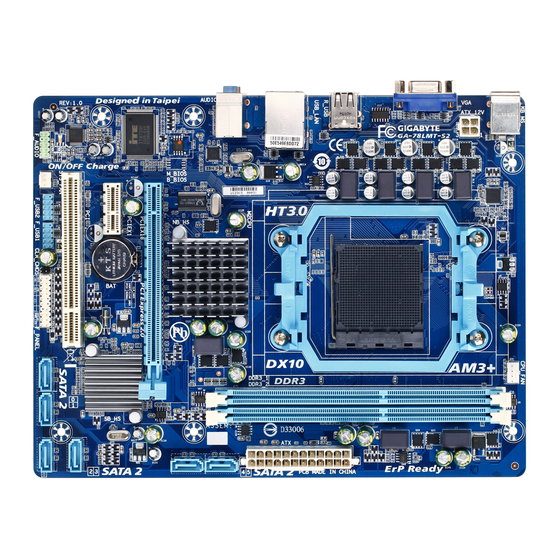
GA-78LMT-S2 Motherboard Layout CPU_FAN KB_MS ATX_12V AM3+ R_USB USB_LAN GA-78LMT-S2 AUDIO AMD 760G GbE LAN F_AUDIO M_BIOS PCIEX16 Super I/O PCIEX1 AMD SB710 CODEC SATA2 F_USB2 F_USB1 F_PANEL CLR_CMOS SYS_FAN Box Contents GA-78LMT-S2 motherboard Motherboard driver disk Two SATA cables... -
Page 6: Ga-78Lmt-S2 Motherboard Block Diagram
GA-78LMT-S2 Motherboard Block Diagram CPU CLK+/- (200 MHz) 1 PCI Express x16 AM3+/AM3 CPU DDR3 1333+ (O.C.)/1066/800 MHz Dual Channel Memory PCIe CLK Hyper Transport 3.0 RJ45 (100 MHz) Realtek GbE LAN GFX CLK (100 MHz) D-Sub AMD 760G PCI Express Bus... -
Page 7: Chapter 1 Hardware Installation
Chapter 1 Hardware Installation Installation Precautions The motherboard contains numerous delicate electronic circuits and components which can become damaged as a result of electrostatic discharge (ESD). Prior to installation, carefully read the user's manual and follow these procedures: • Prior to installation, make sure the chassis is suitable for the motherboard. •... -
Page 8: Product Specifications
1-2 Product Specifications AM3+ Socket: Š AMD AM3+ processor AMD AM3 Phenom II processor/ AMD Athlon II processor ™ ™ (Go to GIGABYTE's website for the latest CPU support list.) Hyper 4400 MT/s Š Transport 3.0 North Bridge: AMD 760G Š Chipset South Bridge: AMD SB710 Š... - Page 9 Internal 1 x 24-pin ATX main power connector Š Connectors 1 x 4-pin ATX 12V power connector Š 6 x SATA 3Gb/s connectors Š 1 x CPU fan header Š 1 x system fan header Š 1 x front panel header Š...
-
Page 10: Installing The Cpu
Bundled Norton Internet Security (OEM version) Š Software Operating Support for Microsoft ® Windows 7/Vista/XP Š System Micro ATX Form Factor; 24.4cm x 18.8cm Form Factor Š * G IGABYTE reserves the right to make any changes to the product specifications and product-related information without prior notice. * Please visit GIGABYTE's website to check the supported operating system(s) for the software listed in the "Unique Features" and "Bundled Software"... -
Page 11: Installing The Memory
Installing the Memory Read the following guidelines before you begin to install the memory: • Make sure that the motherboard supports the memory. It is recommended that memory of the same capacity, brand, speed, and chips be used. (Go to GIGABYTE's website for the latest supported memory speeds and memory modules.) •... -
Page 12: Back Panel Connectors
Back Panel Connectors PS/2 Keyboard and PS/2 Mouse Port Use the upper port (green) to connect a PS/2 mouse and the lower port (purple) to connect a PS/2 keyboard. D-Sub Port The D-Sub port supports a 15-pin D-Sub connector. Connect a monitor that supports D-Sub connection to this port. -
Page 13: Internal Connectors
Internal Connectors 8 10 ATX_12V F_AUDIO F_USB1/F_USB2 CPU_FAN SYS_FAN CLR_CMOS SATA2 0/1/2/3/4/5 F_PANEL Read the following guidelines before connecting external devices: • First make sure your devices are compliant with the connectors you wish to connect. • Before installing the devices, be sure to turn off the devices and your computer. Unplug the power cord from the power outlet to prevent damage to the devices. - Page 14 1/2) ATX_12V/ATX (2x2 12V Power Connector and 2x12 Main Power Connector) With the use of the power connector, the power supply can supply enough stable power to all the components on the motherboard. Before connecting the power connector, first make sure the power supply is turned off and all devices are properly installed. The power connector possesses a foolproof design. Connect the power supply cable to the power connector in the correct orientation.
-
Page 15: Fan Headers
3/4) CPU_FAN/SYS_FAN (Fan Headers) The motherboard has a 4-pin CPU fan header (CPU_FAN) and a 3-pin system fan header (SYS_FAN). Most fan headers possess a foolproof insertion design. When connecting a fan cable, be sure to connect it in the correct orientation (the black connector wire is the ground wire). The speed control function requires the use of a fan with fan speed control design. -
Page 16: F_Panel (Front Panel Header)
6) F_PANEL (Front Panel Header) Connect the power switch, reset switch, speaker, chassis intrusion switch/sensor and system status indicator on the chassis to this header according to the pin assignments below. Note the positive and negative pins before connecting the cables. Message/Power/ Sleep LED Power Switch... -
Page 17: Front Panel Audio Header
7) F_AUDIO (Front Panel Audio Header) The front panel audio header supports Intel High Definition audio (HD) and AC'97 audio. You may connect your chassis front panel audio module to this header. Make sure the wire assignments of the module connector match the pin assignments of the motherboard header. Incorrect connection between the module connector and the motherboard header will make the device unable to work or even damage it. For HD Front Panel Audio: For AC'97 Front Panel Audio: Pin No. - Page 18 9) COM (Serial Port Header) The COM header can provide one serial port via an optional COM port cable. For purchasing the optional COM port cable, please contact the local dealer. Pin No. Definition NDCD- NSIN NSOUT NDTR- NDSR- NRTS- NCTS- NRI- No Pin 10) CLR_CMOS (Clear CMOS Jumper)
-
Page 19: Battery
11) BAT (Battery) The battery provides power to keep the values (such as BIOS configurations, date, and time information) in the CMOS when the computer is turned off. Replace the battery when the battery voltage drops to a low level, or the CMOS values may not be accurate or may be lost. You may clear the CMOS values by removing the battery: 1. -
Page 20: Chapter 2 Bios Setup
The following screens may appear when the computer boots. A. The LOGO Screen (Default) Function Keys B. The POST Screen Award Modular BIOS v6.00PG Copyright (C) 1984-2012, Award Software, Inc. GA-78LMT-S2 F3C Motherboard Model BIOS Version Function Keys <DEL>: BIOS Setup <F9>: XpressRecovery2 <F12>: Boot Menu <End>: Qflash 07/17/2012-RS780L-SB710-7A66CG0SC-00... -
Page 21: The Main Menu
The Main Menu Once you enter the BIOS Setup program, the Main Menu (as shown below) appears on the screen. Use arrow keys to move among the items and press <Enter> to accept or enter a sub-menu. (Sample BIOS Version: F3C) CMOS Setup Utility-Copyright (C) 1984-2012 Award Software Load Fail-Safe Defaults MB Intelligent Tweaker(M.I.T.) -
Page 22: Mb Intelligent Tweaker(M.i.t.)
MB Intelligent Tweaker(M.I.T.) CMOS Setup Utility-Copyright (C) 1984-2012 Award Software MB Intelligent Tweaker(M.I.T.) Item Help IGX Configuration [Press Enter] Menu Level CPU Clock Ratio [Auto] 2800Mhz CPU NorthBridge Freq. [Auto] 2000Mhz Core Performance Boost [Enabled] (Note) CPB Ratio [Auto] 3100Mhz (Note) Turbo CPB [Disabled]... - Page 23 Surround View Enables or disables the Surround View function. This option is configurable only when Init Display First under Advanced BIOS Features is set to PEG and an ATI graphics card is installed. (Default: Disabled) VGA Core Clock control Allows you to determine whether to manually set the VGA Core clock. (Default: Auto) VGA Core Clock(MHz) Allows you to manually set the VGA Core clock. The adjustable range is from 200 MHz to 2000 MHz.
- Page 24 Set Memory Clock Determines whether to manually set the memory clock. Auto lets BIOS automatically set the memory clock as required. Manual allows the memory clock control item below to be configurable. (Default: Auto) Memory Clock This option is configurable only when Set Memory Clock is set to Manual. Options are: X4.00, X5.33, X6.66 and X8.00. DRAM Configuration CMOS Setup Utility-Copyright (C) 1984-2012 Award Software DRAM Configuration Item Help DCTs Mode...
- Page 25 Trfc0 for DIMM1 Options are: Auto (default), 90ns, 110ns, 160ns, 300ns, 350ns. Trfc1 for DIMM2 Options are: Auto (default), 90ns, 110ns, 160ns, 300ns, 350ns. Write Recovery Time Options are: Auto (default), 5T~8T, 10T, 12T. Precharge Time Options are: Auto (default), 4T~7T. Row Cycle Time Options are: Auto (default), 11T~42T.
-
Page 26: Standard Cmos Features
Normal CPU Vcore NB Displays the normal operating voltage of your CPU North Bridge. Standard CMOS Features CMOS Setup Utility-Copyright (C) 1984-2012 Award Software Standard CMOS Features Item Help Date (mm:dd:yy) Mon, Jul 23 2012 Menu Level Time (hh:mm:ss) 22:31:24 ... -
Page 27: Advanced Bios Features
Advanced BIOS Features CMOS Setup Utility-Copyright (C) 1984-2012 Award Software Advanced BIOS Features Item Help IGX Configuration [Press Enter] Menu Level Load Line Control [Auto] AMD C1E Support [Disabled] Virtualization [Disabled] AMD K8 Cool&Quiet control [Auto] CPU Unlock [Disabled] (Note) CPU core Control [Auto] (Note) - Page 28 CPU core Control (Note) Allows you to determine whether to manually enable/disable CPU Core. Auto Lets the BIOS to enable all CPU cores (number of cores available depends on the CPU being used). (Default) Manual Allows you to individually enable/disable CPU Core. &...
-
Page 29: Integrated Peripherals
Init Display First Specifies the first initiation of the monitor display from the installed PCI graphics card, PCI Express graphics card, or the onboard graphics. PCI Slot Sets the PCI graphics card as the first display. (Default) OnChipVGA Sets the onboard graphics as the first display. PEG Sets the PCI Express graphics card on the PCIEX16 slot as the first display. Integrated Peripherals CMOS Setup Utility-Copyright (C) 1984-2012 Award Software Integrated Peripherals Item Help OnChip SATA Controller... - Page 30 OnChip SATA Port as ESP CMOS Setup Utility-Copyright (C) 1984-2012 Award Software OnChip SATA Port as ESP Item Help Port0 as ESP [Disabled] Menu Level Port1 as ESP [Disabled] Port2 as ESP [Disabled] Port3 as ESP [Disabled] x Port4 as ESP Disabled x Port5 as ESP Disabled...
-
Page 31: Power Management Setup
USB Legacy Function Allows USB keyboard to be used in MS-DOS. (Default: Enabled) USB Storage Function Determines whether to detect USB storage devices, including USB flash drives and USB hard drives during the POST. (Default: Enabled) Onboard Serial Port Enables or disables the first serial port and specifies its base I/O address and corresponding interrupt. Options are: Auto, 3F8/IRQ4 (default), 2F8/IRQ3, 3E8/IRQ4, 2E8/IRQ3, Disabled. - Page 32 PME Event Wake Up Allows the system to be awakened from an ACPI sleep state by a wake-up signal from a PCI or PCIe device. Note: To use this function, you need an ATX power supply providing at least 1A on the +5VSB lead.
-
Page 33: Pnp/Pci Configurations
2-8 PnP/PCI Configurations CMOS Setup Utility-Copyright (C) 1984-2012 Award Software PnP/PCI Configurations Item Help PCI1 IRQ Assignment [Auto] Menu Level : Move Enter: Select +/-/PU/PD: Value F10: Save ESC: Exit F1: General Help F5: Previous Values F6: Fail-Safe Defaults F7: Optimized Defaults PCI1 IRQ Assignment Auto BIOS auto-assigns IRQ to the first PCI slot. (Default) -
Page 34: Load Fail-Safe Defaults
Current System/CPU Temperature Displays current system/CPU temperature. Current CPU/SYSTEM FAN Speed (RPM) Displays current CPU/system fan speed. CPU Warning Temperature Sets the warning threshold for CPU temperature. When CPU temperature exceeds the threshold, BIOS will emit warning sound. Options are: Disabled (default), 60 C/140 F, 70 C/158... -
Page 35: Load Optimized Defaults
2-11 Load Optimized Defaults CMOS Setup Utility-Copyright (C) 1984-2012 Award Software MB Intelligent Tweaker(M.I.T.) Load Fail-Safe Defaults Load Optimized Defaults Standard CMOS Features Advanced BIOS Features Set Supervisor Password Integrated Peripherals Set User Password Power Management Setup Save &... -
Page 36: Save & Exit Setup
2-13 Save & Exit Setup CMOS Setup Utility-Copyright (C) 1984-2012 Award Software MB Intelligent Tweaker(M.I.T.) Load Fail-Safe Defaults Load Optimized Defaults Standard CMOS Features Advanced BIOS Features Set Supervisor Password Save to CMOS and EXIT (Y/N)? Y Integrated Peripherals Set User Password ... -
Page 37: Chapter 3 Drivers Installation
Chapter 3 Drivers Installation • Before installing the drivers, first install the operating system. • After installing the operating system, insert the motherboard driver disk into your optical drive. The driver Autorun screen is automatically displayed which looks like that shown in the screen shot below. (If the driver Autorun screen does not appear automatically, go to My Computer, double-click the optical drive and execute the Run.exe program.) After inserting the driver disk, "Xpress Install"... - Page 38 Steps: 1. Turn on your computer and press <Delete> to enter BIOS Setup during the POST (Power-On Self-Test). Ensure OnChip SATA Controller is enabled under Integrated Peripherals. To enable RAID for the SATA2 0/1/2/3 connectors, set OnChip SATA Type to RAID. To enable RAID for the SATA2 4/SATA2 5 connectors, set OnChip SATA Type to RAID and set OnChip SATA Port4/5 Type to As SATA Type.
- Page 39 Making a SATA RAID/AHCI Driver Diskette Before installing Windows XP, connect a USB floppy disk drive to your computer first because you need to install the SATA RAID/AHCI driver from a floppy disk that contains the driver during the OS installation. To copy the RAID/AHCI driver for Windows XP, copy all files in the \BootDrv\Hxp folder in the motherboard driver disk to your floppy disk. To install Windows 7/Vista, you also need to install the SATA RAID/AHCI driver during the OS installation. To copy the RAID/AHCI driver for Windows 7, copy the whole Hw7 folder under the BootDrv folder in the motherboard driver disk to a USB flash drive. Installing the SATA RAID/AHCI Driver and Operating System A.
-
Page 40: Regulatory Statements
Regulatory Statements Regulatory Notices This document must not be copied without our written permission, and the contents there of must not be imparted to a third party nor be used for any unauthorized purpose. Contravention will be prosecuted. We believe that the information contained herein was accurate in all respects at the time of printing. - Page 41 - 41 -...
- Page 42 - 42 -...
- Page 43 - 43 -...
- Page 44 Contact Us GIGA-BYTE TECHNOLOGY CO., LTD. Address: No.6, Bau Chiang Road, Hsin-Tien, Taipei 231, Taiwan TEL: +886-2-8912-4000, FAX: +886-2-8912-4003 Tech. and Non-Tech. Support (Sales/Marketing) : http://ggts.gigabyte.com.tw WEB address (English): http://www.gigabyte.com WEB address (Chinese): http://www.gigabyte.tw You may go to the GIGABYTE website, select your language in the language list on the top right corner of the website. • GIGABYTE Global Service System To submit a technical or non-technical (Sales/Marketing) question, please link to:...
Need help?
Do you have a question about the GA-78LMT-S2 and is the answer not in the manual?
Questions and answers