ASROCK 775i65G User Manual
Hide thumbs
Also See for 775i65G:
- Installation manual (97 pages) ,
- User manual (38 pages) ,
- User manual (85 pages)

Related Manuals for ASROCK 775i65G


Summary of Contents for ASROCK 775i65G
-
Page 1: User Manual
775i65G User Manual Version 3.0 Published June 2012 Copyright©2012 ASRock INC. All rights reserved. 1 1 1 1 1... - Page 2 (including damages for loss of profits, loss of business, loss of data, interruption of business and the like), even if ASRock has been advised of the possibility of such damages arising from any defect or error in the manual or product.
-
Page 3: Table Of Contents
Contents Contents Contents Contents Contents 1 Introduction 1 Introduction ........... 1 Introduction ......................5 ............5 ... 5 ... 5 1 Introduction 1 Introduction ............5 1.1 Package Contents..............5 1.2 Specifications ..............6 1.3 Motherboard Layout ............10 1.4 I/O Panel ................ -
Page 4: Software Support
4 Software Support 4 Software Support 4 Software Support .......... 4 Software Support 4 Software Support ..................................43 4.1 Install Operating System ..........43 4.2 Support CD Information ........... 43 4.2.1 Running Support CD ..........43 4.2.2 Drivers Menu ............43 4.2.3 Utilities Menu ............ -
Page 5: Introduction
In case any modifications of this manual occur, the updated version will be available on ASRock website without further notice. You may find the latest VGA cards and CPU support lists on ASRock website as well. ASRock website http://www.asrock.com If you require technical support related to this motherboard, please visit our website for specific information about the model you are using. -
Page 6: Specifications
Specifications Specifications Specifications Specifications Specifications - Micro ATX Form Factor: 9.6-in x 8.0-in, 24.4 cm x 20.3 cm Platform - LGA 775 for Intel Dual-Core Core 2 Extreme / Core 2 Duo ® / Pentium D / Pentium 4 / Celeron ®... - Page 7 - Chassis Fan Tachometer - CPU Quiet Fan - Voltage Monitoring: +12V, +5V, +3.3V, Vcore - Microsoft Windows 98SE/ME/2000/XP compliant ® ® - FCC, CE, WHQL Certifications * For detailed product information, please visit our website: http://www.asrock.com 7 7 7 7 7...
- Page 8 - ASRock APP Charger. Simply installing the APP Charger driver, it makes your iPhone charged much quickly from your computer and up to 40% faster than before. ASRock APP Charger allows you to quickly charge many Apple devices simultaneously and even supports continuous charging when your PC enters into Standby mode (S1), hibernation mode (S4) or power off (S5).
- Page 9 Although this motherboard offers stepless control, it is not recom- mended to perform over-clocking. Frequencies other than the recom- mended CPU bus frequencies may cause the instability of the system or damage the CPU. 10. While CPU overheat is detected, the system will automatically shutdown. Before you resume the system, please check if the CPU fan on the motherboard functions properly and unplug the power cord, then plug it back again.
-
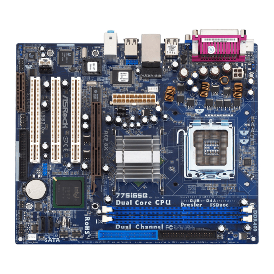
Page 10: Motherboard Layout
1.3 Motherboard Layout 1.3 Motherboard Layout 1.3 Motherboard Layout 1.3 Motherboard Layout 1.3 Motherboard Layout 20.3cm (8.0 in) CPU_FAN1 USB 2.0 T: USB2 B: USB3 Intel USB 2.0 Top: T: USB0 RJ-45 B: USB1 865G Chipset USB 2.0 T: USB4 B: USB5 Super 1.5V_AGP1... -
Page 11: I/O Panel
1.4 I/O P 1.4 I/O P 1.4 I/O P 1.4 I/O P 1.4 I/O Panel anel anel anel anel PS/2 Mouse Port (Green) Shared USB 2.0 Ports (USB45) Parallel Port USB 2.0 Ports (USB01) RJ-45 Port USB 2.0 Ports (USB23) Line In (Light Blue) Serial Port: COM1 Line Out (Lime) -
Page 12: Installation
Chapter 2 Installation Chapter 2 Installation 775i65G is a Micro ATX form factor (9.6" x 8.0", 24.4 x 20.3 cm) motherboard. Before you install the motherboard, study the configuration of your chassis to ensure that the motherboard fits into it. -
Page 13: Cpu Installation
2.3 CPU Installation 2.3 CPU Installation 2.3 CPU Installation 2.3 CPU Installation 2.3 CPU Installation For the installation of Intel 775-LAND CPU, please follow the steps below. 775-Pin Socket Overview Before you insert the 775-LAND CPU into the socket, please check if the CPU surface is unclean or if there is any bent pin on the socket. - Page 14 For proper inserting, please ensure to match the two orientation key notches of the CPU with the two alignment keys of the socket. Step 2-3. Carefully place the CPU into the socket by using a purely vertical motion. Step 2-4. Verify that the CPU is within the socket and properly mated to the orient keys.
-
Page 15: Installation Of Cpu Fan And Heatsink
Installation of CPU Fan and Heatsink Installation of CPU Fan and Heatsink Installation of CPU Fan and Heatsink Installation of CPU Fan and Heatsink Installation of CPU Fan and Heatsink This motherboard is equipped with 775-Pin socket that supports Intel 775-LAND CPU. Please adopt the type of heatsink and cooling fan compliant with Intel 775-LAND CPU to dissipate heat. -
Page 16: Installation Of Memory Modules (Dimm)
2.5 Installation of Memory Modules (DIMM) 2.5 Installation of Memory Modules (DIMM) 2.5 Installation of Memory Modules (DIMM) 2.5 Installation of Memory Modules (DIMM) 2.5 Installation of Memory Modules (DIMM) This motherboard provides two 184-pin DDR (Double Data Rate) DIMM slots, and supports Dual Channel Memory Technology. -
Page 17: Expansion Slots (Pci And Agpslots)
PCI slots: The PCI slots are used to install expansion cards that have the 32-bit PCI interface. AGP slot: The AGP slot is used to install a graphics card. The ASRock AGP slot has a special design of clasp that can securely fasten the inserted graphics card. -
Page 18: Jumpers Setup
2.7 Jumpers Setup 2.7 Jumpers Setup 2.7 Jumpers Setup 2.7 Jumpers Setup 2.7 Jumpers Setup The illustration shows how jumpers are setup. When the jumper cap is placed on pins, the jumper is “Short”. If no jumper cap is placed on pins, the jumper is “Open”. The illustration shows a 3-pin jumper whose pin1 and pin2 are “Short”... -
Page 19: Onboard Headers And Connectors
2.8 Onboard Headers and Connectors 2.8 Onboard Headers and Connectors 2.8 Onboard Headers and Connectors 2.8 Onboard Headers and Connectors 2.8 Onboard Headers and Connectors Onboard headers and connectors are NOT jumpers. Do NOT place jumper caps over these headers and connectors. Placing jumper caps over the headers and connectors will cause permanent damage of the motherboard! FDD connector... - Page 20 USB 2.0 Header The I/O panel accommodates USB_PWR 6 default USB 2.0 ports. If those (9-pin USB67) USB 2.0 ports on the I/O panel DUMMY (see p.10 No. 16) are not sufficient, this USB 2.0 header is available to support 2 additional USB 2.0 ports.
- Page 21 1. +5VA is used for audio power only, please don’t connect it to any other power, such as USB. 2. HD (Azalia) audio front panel and AC’97 audio front panel have different pin-definition. Incorrect connection of the audio front panel and the front panel audio header may cause permanent damage to this motherboard.
- Page 22 ATX 12V Connector Please note that it is necessary to connect a power supply with (4-pin ATX12V2) ATX 12V plug to this connector (see p.10 No. 1) so that it can provides sufficient power. Failing to do so will cause the failure to power up.
-
Page 23: Serial Ata (Sata) Hard Disks Installation
2 . 9 2 . 9 2 . 9 2 . 9 2 . 9 Serial A Serial A Serial A Serial A Serial AT T T T T A (SA A (SA A (SA A (SA A (SAT T T T T A) Hard Disks Installation A) Hard Disks Installation A) Hard Disks Installation A) Hard Disks Installation... -
Page 24: Driver Installation Guide
2.10 Driver Installation Guide 2.10 Driver Installation Guide 2.10 Driver Installation Guide 2.10 Driver Installation Guide 2.10 Driver Installation Guide To install the drivers to your system, please insert the support CD to your optical drive first. Then, the drivers compatible to your system can be auto-detected and listed on the support CD driver page. -
Page 25: Bios Setup Utility
Chapter 3 BIOS SETUP UTILITY Chapter 3 BIOS SETUP UTILITY Chapter 3 BIOS SETUP UTILITY Chapter 3 BIOS SETUP UTILITY Chapter 3 BIOS SETUP UTILITY Introduction Introduction Introduction Introduction Introduction This section explains how to use the BIOS SETUP UTILITY to configure your system. The BIOS FWH chip on the motherboard stores the BIOS SETUP UTILITY. -
Page 26: Navigation Keys
System Time [ :00:09] System Date [Fri 06/15/2012] Use [+] or [-] to configure system Time. BIOS Version : 775i65G BIOS P1.00 Processor Type : Intel (R) CPU 3.40 GHz (64bit supported) Processor Speed : 3400 Select Screen : 1024KB... -
Page 27: Advanced Screen
3 . 3 3 . 3 3 . 3 Advanced Screen Advanced Screen Advanced Screen Advanced Screen 3 . 3 3 . 3 Advanced Screen In this section, you may set the configurations for the following items: CPU Configuration, Chipset Configuration, ACPI Configuration, IDE Configuration, PCIPnP Configuration, Floppy Configuration, SuperIO Configuration, and USB Configuration. - Page 28 Boot Failure Guard Enable or disable the feature of Boot Failure Guard. Spread Spectrum This item should always be [Auto] for better system stability. Ratio Status This is a read-only item, which displays whether the ratio status of this moth- erboard is “Locked”...
- Page 29 Hyper Threading Technology To enable this feature, it requires a computer system with an Intel Pentium ® processor that supports Hyper-Threading technology and an operating system that includes optimization for this technology, such as Microsoft Windows ® ® XP. Set to [Enabled] if using Microsoft Windows XP, or Linux kernel version ®...
-
Page 30: Chipset Configuration
3.3.2 3.3.2 3.3.2 Chipset Configuration Chipset Configuration Chipset Configuration Chipset Configuration 3.3.2 3.3.2 Chipset Configuration BIOS SETUP UTILITY Advanced Chipset Configuration Options DRAM Frequency [Auto] 133MHz (DDR266) [Disabled] Configure DRAM Timing by SPD 166MHz (DDR333) [Auto] 200MHz (DDR400) DRAM CAS# Latency [4 Clocks] DRAM RAS# Precharge Auto... - Page 31 Internal Graphics Mode Select If you select [Auto], the onboard VGA will be automatically disabled when you install VGA card; the onboard VGA will be enabled without the installation of any add-on VGA card. If you select [Enabled, 8MB] or [Enabled, 1MB], the onboard VGA will be enabled.
-
Page 32: Acpi Configuration
3.3.3 3.3.3 ACPI Configuration 3.3.3 ACPI Configuration ACPI Configuration ACPI Configuration 3.3.3 3.3.3 ACPI Configuration BIOS SETUP UTILITY Advanced ACPI Configuration Select auto-detect or disable the STR feature. [Auto] Suspend To RAM Repost Video on STR Resume [No] Restore on AC/Power Loss [Power Off] Ring-In Power On [Disabled]... -
Page 33: Ide Configuration
3.3.4 3.3.4 3.3.4 IDE Configuration 3.3.4 3.3.4 IDE Configuration IDE Configuration IDE Configuration IDE Configuration BIOS SETUP UTILITY Advanced Set [Compatible Mode] IDE Configuration when both Legacy OS (MS-DOS, Win Me / 98SE) [Enhanced Mode] Onboard IDE Operate Mode and SATA device OnBoard IDE Controller [Both] are used. - Page 34 IDE Device Configuration You may set the IDE configuration for the device that you specify. We will use the “Primary IDE Master” as the example in the following instruction, which can be applied to the configurations of “Primary IDE Slave”, “Secondary IDE Master”, “Secondary IDE Slave”, “SATA1”...
-
Page 35: Pcipnp Configuration
PIO Mode Use this item to set the PIO mode to enhance hard disk performance by optimizing the hard disk timing. DMA Mode DMA capability allows the improved transfer-speed and data-integrity for com- patible IDE devices. S.M.A.R.T. Use this item to enable or disable the S.M.A.R.T. (Self-Monitoring, Analysis, and Reporting Technology) feature. -
Page 36: Floppy Configuration
3 . 3 . 6 3 . 3 . 6 3 . 3 . 6 Floppy Configuration 3 . 3 . 6 3 . 3 . 6 Floppy Configuration Floppy Configuration Floppy Configuration Floppy Configuration In this section, you may configure the type of your floppy drive. BIOS SETUP UTILITY Advanced Floppy Configuration... - Page 37 Parallel Port Address Use this item to set the address for the onboard parallel port or disable it. Configuration options: [Disabled], [378], and [278]. Parallel Port Mode Use this item to set the operation mode of the parallel port. The default value is [ECP+EPP].
-
Page 38: Usb Configuration
3.3.8 3.3.8 USB Configuration 3.3.8 USB Configuration USB Configuration USB Configuration 3.3.8 3.3.8 USB Configuration BIOS SETUP UTILITY Advanced USB Configuration To enable or disable the onboard USB controllers. [Enabled] USB Controller [Enabled] USB 2.0 Support Legacy USB Support [Auto] Select Screen Select Item Change Option... -
Page 39: Hardware Health Event Monitoring Screen
3.4 Hardware Health Event Monitoring Screen Hardware Health Event Monitoring Screen Hardware Health Event Monitoring Screen Hardware Health Event Monitoring Screen Hardware Health Event Monitoring Screen In this section, it allows you to monitor the status of the hardware on your system, including the parameters of the CPU temperature, motherboard temperature, CPU fan speed, chassis fan speed, and the critical voltage. -
Page 40: Boot Screen
3.5 Boot Screen Boot Screen Boot Screen Boot Screen Boot Screen In this section, it will display the available devices on your system for you to config- ure the boot settings and the boot priority. BIOS SETUP UTILITY Main Advanced H/W Monitor Boot Security... -
Page 41: Boot Device Priority
3.5.2 3.5.2 Boot Device Priority Boot Device Priority 3.5.2 3.5.2 3.5.2 Boot Device Priority Boot Device Priority Boot Device Priority In this section, you may specify the boot sequence from the available devices in your system. BIOS SETUP UTILITY Boot Specifies the boot Boot Device Priority sequence from the... -
Page 42: Exit Screen
3.7 Exit Screen Exit Screen Exit Screen Exit Screen Exit Screen BIOS SETUP UTILITY Main Advanced H/W Monitro Boot Security Exit Exit Options Exit system setup after saving the changes. Save Changes and Exit Discard Changes and Exit F10 key can be used Discard Changes for this operation. -
Page 43: Install Operating System
4 . 2 . 4 4 . 2 . 4 Contact Information If you need to contact ASRock or want to know more about ASRock, welcome to visit ASRock’s website at http://www.asrock.com; or you may contact your dealer for further information.
Need help?
Do you have a question about the 775i65G and is the answer not in the manual?
Questions and answers