Panasonic FP2 Manual
Programmable controller computer communication unit
Hide thumbs
Also See for FP2:
- User manual (102 pages) ,
- Technical manual (68 pages) ,
- Product manual (29 pages)
Table of Contents
Advertisement
Quick Links
Advertisement
Table of Contents

Related Manuals for Panasonic FP2


Summary of Contents for Panasonic FP2
-
Page 2: Safety Precautions
It could lead to an electric shock. Copyright / Trademarks -This manual and its contents are copyrighted. Panasonic Electric -You may not copy this manual, in whole or part, without written consent of Works SUNX Co., Ltd. -
Page 3: Table Of Contents
Communication Conditions and Restrictions Relating to Functions ..1 − 8 1.4.1 Precautions when Using the FP2 CPU Unit−1 ....1 − 8 1.4.2 Precautions when Using the FP2 CPU Unit−2... - Page 4 Table of Contents FP2−CCU Chapter 4 RS232C Port Wiring RS232C Port Signals ..........
-
Page 5: Interchangeability With The Fp3 And Precautions
Interchangeability with the FP3 and Precautions Hardware interchangeability The user should be aware that there are some differences between the FP2 and FP3 Computer Communication Units. − The DIP switch settings are different. With the FP2 Computer Communication Unit, only the transmission speed and the character bit can be set with the DIP switches. - Page 6 Interchangeability with the FP3 and Precautions FP2−CCU Comparison of specifications between the FP2 and FP3 Computer Communication Units Setting item Set value No. of ports — 2 ports 1 port Transmission speed (Baud rate) 19,200 bits/s 9,600 bits/s 4,800 bits/s 2,400 bits/s —...
-
Page 7: Functions Of Computer Communication Unit
......1 − 8 1.4.1 Precautions when Using the FP2 CPU Unit−1 ......1 − 8 1.4.2 Precautions when Using the FP2 CPU Unit−2... - Page 8 Functions of Computer Communication Unit FP2−CCU 1 − 2...
- Page 9 1.1.1 Functions and Features The FP2 Computer Communication Unit is designed for use with the FP2/FP2SH progra,mmable controller. It is used as a communication interface that allows data to be read and written between an RS232C device such as a personal computer or display panel, and a CPU unit.
- Page 10 Functions of Computer Communication Unit FP2−CCU Unit Operation Unit Operation 1.2.1 Operation Overview The Computer Communication Unit reads and writes data and contacts of the CPU unit by the host computer, through an RS232C interface. When a command is sent from a host side, a response is returned from the PLC side.
- Page 11 FP2−CCU Functions of Computer Communication Unit Unit Operation Note This unit does not support extension header (<). Use the Multi Communication Unit. MEWTOCOL communication protocol for FP series are generally configured as shown below. Command format (Example showing command for reading data)
- Page 12 60 mA or less FP2 Computer Communication Unit For information on the internal current consumptions of other units, please refer to the “FP2/FP2SH Hardware Manual” and the manuals of the pertinent units. 1.3.2 Restrictions on Installation Position The Computer Communication Unit can only be installed on the CPU backplane side.
- Page 13 The above restrictions do not apply to Multi−wire Link Units set to the MEWNET−F mode and MEWNET−W2 mode. Note If the FP2 CPU unit is being used, make sure the restrictions relating to the following communication conditions have been carefully confirmed when deciding the number of units to be installed.
- Page 14 Relating to Functions 1.4.1 Precautions when Using the FP2 CPU Unit −1 If the processing of commands and responses sent from a host computer or display panel extends over multiple frames, a busy error (error code 53) will be returned to other ports if communication is currently being carried out on one port, and communication will be inhibited on those other ports.
- Page 15 − If using the FP2SH CPU unit, the above restriction does not apply. 1.4.2 Precautions when Using the FP2 CPU Unit−2 Of the commands sent from a host computer or display panel, if the monitor commands (the MC, MD, and MG codes) are used, they cannot be read accurately if two or more devices within the same group are connected.
- Page 16 Functions of Computer Communication Unit FP2−CCU Communication Conditions and Restrictions Relating to Functions A similar restriction also applies if access is being made from another station connected with the link unit. 5 1 5 ¦ Unit No. 1 (source station) Unit No.
- Page 17 Chapter 2 Names and Functions of Parts Names and Functions of Parts ....2 − 3 2.1.1 Names and Functions of Parts .
- Page 18 Names and Functions of Parts FP2−CCU 2 − 2...
-
Page 19: Names And Functions Of Parts
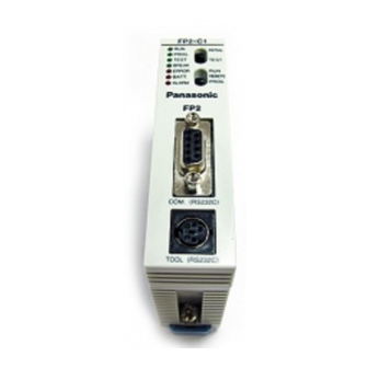
FP2−CCU Names and Functions of Parts 2.1 Names and Functions of Parts Names and Functions of Parts 2.1.1 Names and Functions of Parts Front Back Operating status LEDs This displays the operating status of the unit, such as communication conditions and error/alarm situations. -
Page 20: Operating Status Leds
Names and Functions of Parts FP2−CCU Names and Functions of Parts 2.1.2 Operating Status LEDs These display the operating status of the unit, such as communication conditions and error/alarm situations. Display Operation ALARM (red) Lighted: Unit error (lights on watchdog timer error) Not lighted: Goes out when there is no error COM. -
Page 21: Com.1 And Com.2 Ports (9 Pins)
FP2−CCU Names and Functions of Parts 2.1 Names and Functions of Parts 2.1.3 COM.1 and COM.2 Ports (9 Pins) These are used to connect the RS232C connector of an RS232C device such as a personal computer or display panel, using a shielded cable. -
Page 22: Transmission Format Setting Switch
Names and Functions of Parts FP2−CCU Names and Functions of Parts 2.1.4 Transmission Format Setting Switch These switches are used to set the transmission speed (baud rate) and character bit for the COM.1 and COM.2 ports. The values set by these switches are automatically reflected when the power supply is turned on. - Page 23 Chapter 3 Confirming Unit Settings and Design Contents Setting the Transmission Speed (Baud Rate) and Transmission Format ......3 −...
- Page 24 Confirming Unit Settings and Design Contents FP2−CCU 3 − 2...
-
Page 25: Chapter 3 Confirming Unit Settings And Design Contents
With the FP2 Computer Communication Unit, the transmission format setting switches (DIP switches) can be used to change only the transmission speed (baud rate) and character bit to match those of the external device. - Page 26 Confirming Unit Settings and Design Contents FP2−CCU Note The No. 1 and No. 5 transmission format setting switches are reserved for system use. These are set to “on” when the unit is shipped from the factory, and should be left at that setting.
-
Page 27: Confirming The I/O Allocation And Root No
• If the CPU unit being used is a dual−module type, make sure any occupied I/O areas incorporated in the CPU unit are also checked. For information on I/O allocations, please refer to the “FP2/FP2SH Hardware Manual”. 3 − 5... -
Page 28: Confirming Root No
Confirming Unit Settings and Design Contents FP2−CCU Confirming the I/O Allocation and Root No. 3.2.2 Confirming Root No. If multiple Computer Communication Units have been installed, they are labeled “Root No. 1”, “Root No. 2”, and “Root No. 3” in sequential order, starting from the unit closest to the CPU unit. - Page 29 Chapter 4 RS232C Port Wiring RS232C Port Signals ......4 − 3 Wiring between RS232C Ports .
- Page 30 RS232C Port Wiring FP2−CCU 4 − 2...
-
Page 31: Rs232C Port Signals
Communication Unit, the RS signal is constantly on. CS (Clear to Send) This signal goes on when the partner device is ready to receive data. With the FP2 Computer Communication Unit, input to this terminal is invalid, so no connections are necessary. SG (Signal Ground) This signal provides a common reference potential for circuits connected to the Computer Communication Unit and any external devices. - Page 32 RS232C Port Signals CD (Receive Carrier Detect) This signal goes on when the reception signal is within the specified range. With the FP2 Computer Communication Unit, input to this terminal is invalid, so no connections are necessary. ER (Equipment Ready) This signal notifies the partner device that the Computer Communication Unit is ready for operation.
-
Page 33: Wiring Between Rs232C Ports
FP2−CCU RS232C Port Wiring 4.2 Wiring between RS232C Ports Wiring between RS232C Ports The Computer Communication Unit and RS232C devices should be connected using shielded cables. 4.2.1 Connecting to a Personal Computer An RS232C cable (Product No. AFB85853) is available for making connections to a personal computer. -
Page 34: Connections With Operation Display Panel
RS232C Port Wiring FP2−CCU Wiring between RS232C Ports 4.2.2 Connections with Operation Display Panel An RS232C cable (Product No. AFB85813) is available for making connections to an operation display panel that has a D−sub 25−pin connector. AFB85813 (Crossing cable: 9−pin external — 25−pin external) Dimension M2.6 screws... -
Page 35: Connections With Rs232C Devices
FP2−CCU RS232C Port Wiring 4.2 Wiring between RS232C Ports 4.2.3 Connections with RS232C Devices Connections with an RS232C device that has a D−sub 9−pin connector should be made as follows. Computer Communication RS232C side (9−pin) Unit side Pin No. Mnemonic Pin No. -
Page 36: Modem Connections
RS232C Port Wiring FP2−CCU Wiring between RS232C Ports 4.2.4 Modem Connections An RS232C cable (Product No. AFB85843) is available for making connections to a modem. AFB85843 (Straight cable for modem connection: 9−pin external — 25−pin external) Dimension M2.6 screws 100 ... - Page 37 Chapter 5 Troubleshooting Operation if an Error Occurs ..... . 5 − 3 5.1.1 If the ALARM LED on the Computer Communication Unit Lights .
- Page 38 Troubleshooting FP2−CCU 5 − 2...
-
Page 39: Operation If An Error Occurs
FP2−CCU Troubleshooting Operation if an Error Occurs Operation if an Error Occurs 5.1.1 If the ALARM LED on the Computer Communication Unit Lights What the ALARM LED does The ALARM LED on the Computer Communication Unit lights if the watchdog timer in the unit is activated, to warn of a problem. -
Page 40: If The Error Led On The Computer Communication Unit Lights
Troubleshooting FP2−CCU Operation if an Error Occurs 5.1.2 If the ERROR LED on the Computer Communication Unit Lights What the ERROR LED does The ERROR LED on the Computer Communication Unit lights there is a problem with communication between the unit and the external device. There are two ERROR LEDs, ERR1 and ERR2, for each channel. -
Page 41: What To Do If An Error Occurs
FP2−CCU Troubleshooting What to Do if an Error Occurs What to Do if an Error Occurs 5.2.1 If the ALARM LED on the Computer Communication Unit Lights Situation The watchdog timer is activated to alert the user of a problem with the Computer Communication Unit. -
Page 42: Communication Is Inhibited
Troubleshooting FP2−CCU What to Do if an Error Occurs 5.2.3 Communication is Inhibited Situation There is a possibility that the cables have not been connected correctly. Solution If using the unit for the first time, there is a possibility that the cables have been connected incorrectly. -
Page 43: Chapter 6 Specifications
Chapter 6 Specifications Specifications ........6 − 3 Table of MEWTOCOL Command . - Page 44 Specifications FP2−CCU 6 − 2...
-
Page 45: Specifications
FP2−CCU Specifications Specifications Specifications General Specifications Item Specifications Ambient temperature 0 to 55 °C/32 to 131 °F Storage temperature –20 to +70 °C/– 4 to + 158°F Ambient humidity 30 to 85 % RH (at 25°C non−condensing) Storage humidity 30 to 85 % RH (at 25°C non−condensing) Vibration resistance 10 to 55 Hz, 1 cycle/min.: double amplitude 0.75 mm (0.03 in.),... -
Page 46: Table Of Mewtocol Command
Specifications FP2−CCU Table of MEWTOCOL Command Table of MEWTOCOL Command The following is a table of MEWTOCOL commands that can be used with the FP2 Computer Communication Unit. 6.2.1 MEWTOCOL−COM Commands Read single point of contact information Write single point of contact information... -
Page 47: Table Of Mewtocol−Com Error Code
This occurs if the communication format between the host computer side and the PLC side is different. • Precautions when the FP2 Computer Communication Unit is being used If the parity settings are different, the ERR LED lights but no error code is returned. - Page 48 • Example of error This occurs when a WD command is sent, if the data being sent at one time exceeds 118 bytes. • ERR LED on the FP2 Computer Communication Unit Lights 40 BCC Error: • Situation Transmission error occurred in command data.
- Page 49 This occurs when a command consisting of multiple frames is sent, if the delimiter “&” that indicates that the command is a continuation of the previously sent command is missing. • ERR LED on the FP2 Computer Communication Unit 53 Busy Error: • Situation Commands cannot be received while another command is being processed.
- Page 50 Example of error This occurs if the data register specification is in hexadecimal format when an RD command is sent. • ERR LED on the FP2 Computer Communication Unit 62 Registration Error: • Situation Too many registrations have been entered, or a registration has not been entered.
- Page 51 Example of error This occurs if a program address is specified that is larger than the unit side, when an RP command is sent. • ERR LED on the FP2 Computer Communication Unit 67 Missing Data Error: • Situation The data specified for reading does not exist.
- Page 52 Specifications FP2−CCU Table of MEWTOCOL−COM Error Code 6 − 10...
-
Page 53: Record Of Changes
Record of changes Manual No. Date Description of changes ARCT1F319E/ MAR.2001 First edition ACG-M319E ARCT1F319E-1/ NOV.2006 Second edition ACG-M319E-1 ARCT1F319E-2/ NOV.2008 Third eidition ACG-M319E-2 - Change in Corporate name ARCT1F319E-3 AUG.2011 Fourth eidition - Change in Corporate name... - Page 54 Record of changes FP2−CCU R − 2...