Table of Contents
Advertisement
Advertisement
Table of Contents
Troubleshooting

Related Manuals for Allen-Bradley MicroLogix 1761-NET-ENI


Summary of Contents for Allen-Bradley MicroLogix 1761-NET-ENI
-
Page 1: Ethernet Interface
MicroLogix™ Ethernet Interface (ENI) (Cat. No. 1761-NET-ENI) User Manual... - Page 2 Since there are many variables and requirements associated with any particular installation, Allen-Bradley does not assume responsibility or liability (to include intellectual property liability) for actual use based upon the examples shown in this publication.
-
Page 3: Table Of Contents
Table of Contents Preface Who Should Use this Manual..... . . P-1 Purpose of this Manual ......P-1 Common Techniques Used in this Manual . - Page 4 Table of Contents Chapter 6 E-Mail Messages (Node 50 to 99) Overview ........6-1 Configuring E-Mail .
-
Page 5: Who Should Use This Manual
If you do not, contact your local Allen-Bradley representative for information on available training courses before using this product. Purpose of this Manual This manual is a reference guide for the Ethernet Interface (ENI). -
Page 6: Common Techniques Used In This Manual
Ethernet Interface Installation 1761-IN006A-MU-P Instructions Information on DF1 open protocol. DF1 Protocol and Command Set 1770-6.5.16 Reference Manual In-depth information on grounding and wiring Allen-Bradley Allen-Bradley Programmable 1770-4.1 programmable controllers Controller Grounding and Wiring Guidelines A description of important differences between solid-state Application Considerations for SGI-1.1... -
Page 7: Rockwell Automation Support
Preface Rockwell Automation Rockwell Automation offers support services worldwide, with over 75 Sales/Support Offices, 512 authorized Distributors and 260 authorized Support Systems Integrators located throughout the United States alone, plus Rockwell Automation representatives in every major country in the world. Local Product Support Contact your local Rockwell Automation representative for: sales and order support... - Page 8 Preface Publication 1761-UM006A-EN-P - January 2001...
-
Page 9: Ethernet Connection
Allen Bradley Ethernet controllers (SLC, PLC, and ControlLogix) in a peer-to-peer relationship, so you do not need any master-type device. Non-Ethernet Devices The ENI allows you to connect non-Ethernet Allen-Bradley programmable controllers to Ethernet networks. The ENI uses Ethernet/IP services to allow these controllers to intercommunicate via their native PCCC messaging. -
Page 10: Hardware Features
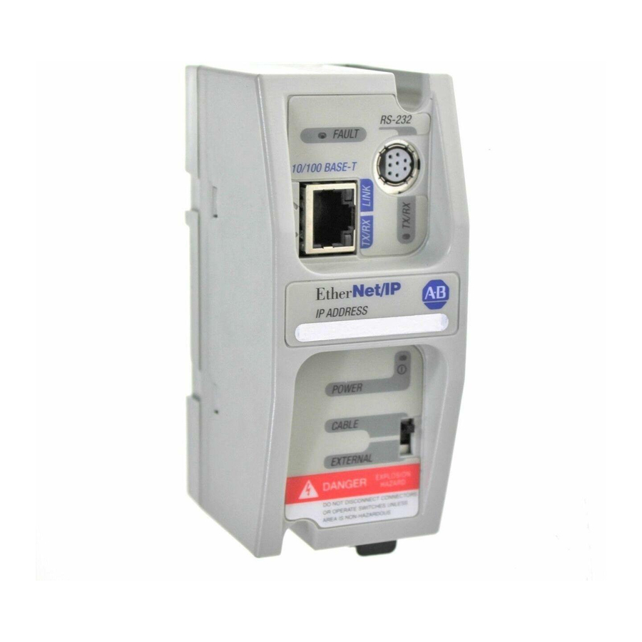
Product Overview The ENI also supports an SMTP mail service that allows an existing controller to send e-mail messages to any destination connected to the network. The e-mail can be used to initiate the transmission of data or status information. Hardware Features Product Drawing RS-232... -
Page 11: Default Settings
Product Overview Default Settings The ENI’s RS-232 port has the following default settings: Table 1.1 RS-232 Settings Setting Default Other Options Baud Rate Autobaud see table 4.7 Handshaking (hardware, software) none none Data Bits none Stop Bits none Parity none none Table 1.2 DF1 Settings Setting... -
Page 12: Operating Modes
Product Overview Operating Modes Messaging When the ENI is connected to a programmable controller (and connected to an Ethernet network), the controller can be accessed from other devices on Ethernet, or initiate communications to other Ethernet/IP devices. E-Mail The ENI also supports SMTP mail service, that allows a controller to send e-mail messages to any e-mail address on the network. -
Page 13: Ethernet Networks
Product Overview Ethernet Networks Basic Ethernet Topology The ENI Ethernet connector conforms to ISO/IEC 8802-3 STD 802.3 and utilizes 10Base-T media. Connections are made directly from the ENI to an Ethernet switch. The network setup is simple and cost effective. Typical network topology is pictured below. RJ45 connectors Ethernet on both ends of... - Page 14 Product Overview Publication 1761-UM006A-EN-P - February 2001...
-
Page 15: European Communities (Ec) Directive Compliance
Chapter Installation and Wiring This chapter covers installation and wiring for the ENI. It is divided into the following sections: European Communities (EC) Directive Compliance Safety Considerations Mounting External Power Supply Wiring ENI Port Identification Ethernet Connections RS-232 Port Connections European Communities (EC) This product has the CE mark. -
Page 16: Safety Considerations
Installation and Wiring Tests. For specific information required by EN 61131-2, see the appropriate sections in this publication, as well as the Allen-Bradley publication Industrial Automation Wiring and Grounding Guidelines For Noise Immunity, publication 1770-4.1. Open style devices must be provided with environmental and safety protection by proper mounting in enclosures designed for specific application conditions. -
Page 17: Mounting
Installation and Wiring Mounting The 1761-NET-ENI must be mounted in the vertical position, as shown. Horizontal mounting is not recommended due to thermal considerations. Allow 50 mm (2 in.) of space on all sides for adequate ventilation. See page A-1 for operating temperature specification. protective debris strip ETHERNET RS232... - Page 18 Installation and Wiring Removal 1. Place a screwdriver in the DIN rail latch at the bottom of the unit. Side Rail View 2. Holding the unit, pry downward on the latch until the unit is released from the DIN rail. Panel Mounting Template See Appendix A for panel mounting template.
-
Page 19: Eni Port Identification
Installation and Wiring ENI Port Identification ETHERNET RS232 FAULT RS-232 Mini-DIN (ENI Port 2) TX/RX TX/RX Ethernet Port (ENI Port 1) Write-on area for Ethernet IP address CABLE EXTERNAL External Power Supply Wiring EXPLOSION HAZARD - In Class I Division 2 WARNING applications, an external, Class 2 power supply must be used. -
Page 20: Ethernet Connections
Installation and Wiring Ethernet Connections Ethernet 8-Pin 10Base-T Connector (Port 1) The Ethernet connector is an RJ45, 10Base-T connector. The pin-out for the connector is shown below: Pin Name not used by 10Base-T not used by 10Base-T not used by 10Base-T not used by 10Base-T When to use straight-through and cross-over cable: ENI Ethernet port to 10Base-T Ethernet switch cables utilize a... - Page 21 Installation and Wiring Ethernet Cables Shielded and non-shielded twisted-pair 10Base-T cables with RJ45 connectors are supported. The maximum cable length between an ENI Ethernet port and a 10Base-T port on an Ethernet switch (without repeaters or fiber) is 100 meters (323 feet). However, in an industrial application, the cable length should be kept to a minimum.
-
Page 22: Rs-232 Port Connections
Installation and Wiring RS-232 Port Connections RS-232 Connector 8-pin mini-DIN Table 2.1 RS-232 Connector Pin Assignments Port 2 24V dc ground (GND) no connection ENI input data, RxD no connection no connection ENI output data, TxD ground (GND) RS-232 Cables Port 2 of the ENI is an 8-pin mini-DIN RS-232 port that provides connection to DF1 compatible RS-232 devices. -
Page 23: Chapter 3 Operation Overview
Chapter Operation This chapter describes ENI operation. The following information is included: Operation Overview Allocation of Ethernet Connections ENI Functional Overview Program Upload/Download and On-Line Sessions Operation Overview Ethernet is the protocol used to transport TCP/IP messages. On top of TCP, Ethernet/IP is the open protocol used by the ENI. -
Page 24: Eni Functional Overview
The ENI provides Ethernet/IP connectivity for RS-232 devices that use DF1 full-duplex protocol. DF1 full-duplex is an open, point-to-point protocol used in any Allen-Bradley controller with an RS-232 port, and in many other devices. DF1 full-duplex supports up to 256 nodes. The ENI uses these nodes for different functions. - Page 25 Operation 2. The “Configure Dialog” will open, select Ethernet devices from the available drivers, and then click “OK” to load the driver into RSLinx. Once the Ethernet driver is loaded, either highlight and select “Configure” or simply double click on the Ethernet driver. Publication 1761-UM006A-EN-P - February 2001...
- Page 26 Operation At that point the station mapping screen will appear as illustrated here. Double click on the row below “Host Name”, and enter the TCP/IP addresses that match the devices on your network that you will need access to. When you are done entering the stations, click OK to close the station mapping window.
- Page 27 Operation 3. Open the AB_ETH-1 tree on your computer, autobrowse should be running and any active device that you have configured should be shown on the screen as illustrated below. RSLogix 500 1. Open RSLogix 500 and select “Comms” Publication 1761-UM006A-EN-P - February 2001...
- Page 28 Operation 2. Select “AB_ETH-1, Ethernet. 3. Either expand the tree (select the + in the box, or select the device from the table to the right. From this point, you can then either go online or perform an upload or download. Publication 1761-UM006A-EN-P - February 2001...
-
Page 29: Configuration Methods
Configuration Methods The ENI’s IP information can be entered using either: the ENI Configuration Utility a write message from the Allen-Bradley controller to node address 250 the BOOTP Utility over Ethernet (BOOTP configuration is described in Appendix B of this manual) - Page 30 ENI Configuration (Node 248 to 254) COM Port Settings Use the Utility Settings screen to set the following: COM Port - The PC’s RS-232 port that the communications cable is plugged into. Baud Rate - Select a baud rate or choose Autobaud. See page 4-15 for more information.
- Page 31 ENI Configuration (Node 248 to 254) If you want to obtain the TCP/IP information via BOOTP, you must do that separately from the ENI Configuration Utility. See Appendix B. Save to ENI RAM or ENI ROM You must save the configurations you have set. Click ENI RAM for temporary setups or ENI ROM to permanently save your settings.
- Page 32 ENI Configuration (Node 248 to 254) Message Routing Use the Message Routing screen to fill in the destination addresses for DF1 messaging. Message routing is described in chapter 5. Reset Use the Reset screen to issue reset commands and to set the type of behavior that will occur at reset.
-
Page 33: Controller Messaging
TCP/IP configuration parameters. A CIF write message is initiated to the controller. CIF stands for Common Interface File and is supported by all Allen-Bradley programmable controllers that have an RS-232 port. The first item to configure is the ENI’s IP address on your network. -
Page 34: Configuring Eni Data Parameters
ENI Configuration (Node 248 to 254) Configuring ENI Data This example illustrates how to configure the ENI’s TCP/IP address Parameters (Node 250). This procedure can also be used for any parameter that requires integer numbers (nodes 50 to 150, 250, 251, 252 and 253). - Page 35 ENI Configuration (Node 248 to 254) 3. Open the message instruction and enter the appropriate variables. The variables are described in Table 4.1. Table 4.1 Message Instruction Variables for Configuring ENI Data Parameters Variable Setting This Controller Parameters: Communication For the ENI configuration, this must be set to: Command 485CIF for MicroLogix and SLC an unprotected write command for CompactLogix and...
-
Page 36: Configuring Eni String Parameters
ENI Configuration (Node 248 to 254) Configuring ENI String Configuring the ENI E-Mail From String Parameters This example illustrates configuring the ENI E-mail From String (Node 249). To configure the E-mail From String, initiate a message with a string element as the data. Node 249 - E-Mail From String EXAMPLE Node 249 holds the ASCII string that will be sent... - Page 37 ENI Configuration (Node 248 to 254) 2. Create your message logic using whatever conditional instructions you may need. This example uses bit B3:0/7 to condition the MSG instruction and message file 10, element 16 to manage the message session. 3. Open the message instruction and enter the appropriate variables.
-
Page 38: Eni Configuration Parameters
4-10 ENI Configuration (Node 248 to 254) ENI Configuration The following table shows the functions that nodes 248 to 255 perform and their default values. Descriptions of each function can be Parameters found following the table. Node Function Data Type Number of Options Default... - Page 39 ENI Configuration (Node 248 to 254) 4-11 Node 248 - Save/Reset Function Depending on the value of the Save/Reset option, the ENI performs the following operations when receiving a PCCC Unprotected Write message of one element (integer) to Node 248. Value of ENI Operation Save/Reset...
- Page 40 This procedure describes configuration for the TCP/IP parameters. The TCP/IP parameters are configured by sending a message instruction to the ENI (or by using the ENI Configuration Utility). 1. Configure a 485CIF write message in the Allen-Bradley controller. Only PLC2 type or 485CIF read/write messages IMPORTANT can be used to configure the ENI.
- Page 41 ENI Configuration (Node 248 to 254) 4-13 Subnet Mask A subnet mask is used to interpret IP addresses when the network is divided into subnets. If your network is not divided into subnets, then leave the subnet mask at the default or allow the ENI Configuration Utility to assign a default.
- Page 42 4-14 ENI Configuration (Node 248 to 254) The security masks default value is 0.0.0.0 out-of-box, which is defined as “accept all register session requests”. A Security Mask of 255.255.255.255 is also defined as “accept all register session requests”. The security mask acts as a filter on the source IP address such that any mask octet set to the value of 255 becomes “don’t care”...
- Page 43 ENI Configuration (Node 248 to 254) 4-15 Node 251 - E-Mail Server The TCP/IP address stored in this location defines the mail server. The ENI sends all e-mail requests to this server, which then sends the e-mail message to the destination. Node 252 - BOOTP Configuration The ENI allows the BOOTP request to be disabled by clearing the BOOTP Enable parameter in the channel Configuration File.
- Page 44 4-16 ENI Configuration (Node 248 to 254) Table 4.7 ENI Baud Rate Options Configuration Value (Integer) Baud Rate 0x0000 Autobaud Enabled 0x0001 1200 0x0002 2400 0x0003 4800 0x0004 9600 0x0005 19.2K 0x0006 38.4K 0x0007 57.6K 8 to 65535 Autobaud Enabled (1) All CompactLogix devices must be configured to use two stop bits when communicating with the ENI at 38.4K.
-
Page 45: Messaging Between The Eni And Df1 Devices
Chapter Peer-to-Peer Messaging This chapter describes messaging between the ENI and DF1 devices. The following topics are covered: Messaging Between the ENI and DF1 Devices Message to Configuration Nodes (Nodes 100 to 149) Sending a Message to a Destination Controller (Nodes 0 to 49) Messaging Between the The ENI can route a DF1 message received from the attached controller to a compatible destination TCP/IP device. - Page 46 Peer-to-Peer Messaging The table below illustrates the relationship between messages and their corresponding configuration addresses. Table 5.1 Message Routing ENI receives read or ENI TCP/IP route Message forwarded to destination write PCCC message to configuration node TCP/IP address Node 0 Node100 111.222.233.200 (stored at Node 100) Node 1...
-
Page 47: Message To Configuration Nodes (Nodes 100 To 149)
Peer-to-Peer Messaging Message to Configuration When the ENI receives a message to Node Address 0 to 49, it looks up the TCP/IP address associated with the address at Nodes 100 to 149. Nodes (Nodes 100 to 149) The ENI preserves the original DF1 address when sending back a reply. -
Page 48: Sending A Message To A Destination Controller (Nodes 0 To 49)
Peer-to-Peer Messaging Sending a Message to a The ENI uses a pair of node addresses to send data messages over TCP/IP. For data, two sets of addresses are used as illustrated in the Destination Controller table below. Node numbers 100 to 149 are used to define or store the (Nodes 0 to 49) actual TCP/IP address, and nodes 0 to 49 are used to send the data to the destination. - Page 49 Peer-to-Peer Messaging Open the message instruction and enter the appropriate variables. The variables are described in Table 5.4. Table 5.4 Message Instruction Variables for Sending a Message to a Destination Controller Variable Setting This Controller Parameters: Communication Command Use any command supported by your controller. Data Table Address Use any valid file.
- Page 50 Peer-to-Peer Messaging Publication 1761-UM006A-EN-P - February 2001...
-
Page 51: Chapter 6 Overview
Chapter E-Mail Messages (Node 50 to 99) This chapter describes using the ENI’s e-mail feature. The following topics are included: Overview Configuring E-Mail Sending an E-Mail Message Overview The ENI is capable of transmitting e-mail messages generated by the attached controller. This provides an extremely versatile mechanism to report alarms, status, and other data-related functions. -
Page 52: Configuring E-Mail
E-Mail Messages (Node 50 to 99) Configuring E-Mail SMTP E-Mail Address To configure the e-mail function, two parameters must be configured: SMTP mail server IP address - configured by sending a write message to node 251 (e-mail server). See page 4-15 for more information. - Page 53 E-Mail Messages (Node 50 to 99) Destination Addresses The ENI stores e-mail addresses; it does not store the e-mail messages. To store a destination address, write a message to a specific node number (nodes 150 to 199). The message data must be a string element that contains a valid e-mail ASCII text string address, as illustrated in ST15:0 through ST15:5 in the example below.
- Page 54 E-Mail Messages (Node 50 to 99) E-Mail E-Mail Address Description Message Configuration Node 50 Node 150 The data within the message is sent to Node 50 and forwarded to the e-mail address stored at Node 150. Node 51 Node 151 The data within the message is sent to Node 51 and forwarded to the e-mail address stored at Node 151.
-
Page 55: Sending An E-Mail Message
E-Mail Messages (Node 50 to 99) Sending an E-Mail The ENI uses a pair of node addresses to send e-mail or data messages over TCP/IP. To send e-mail, two sets of addresses are used Message as illustrated in the table below. Node numbers 150 to 199 are used to define or store the actual e-mail address, and nodes 50 to 99 are used to send the string element to the e-mail recipient. - Page 56 E-Mail Messages (Node 50 to 99) 2. Open the message instruction and enter the appropriate variables. The variables are described in Table 6.1. Table 6.1 Message Instruction Variables for Sending an E-Mail Message Variable Setting This Controller Parameters: Communication Command Use any command supported by your controller.
-
Page 57: System Diagram
Chapter Connecting 1769-L20 CompactLogix Controllers on Ethernet The chapter contains an example of using the ENI on an Ethernet network. It is arranged as follows: System Diagram Purpose Scope General Ethernet Information Configuring 1761-NET-ENI #1 Configuring 1761-NET-ENI #2 Configure RSLINX and Download The Program To The 1769-L20 Create MSG Programs for the SLC 5/05 and the 5550 Controllers Configuring an Ethernet Driver in RSLINX System Diagram... -
Page 58: Purpose
Connecting 1769-L20 CompactLogix Controllers on Ethernet The computer must include the following software: RSLOGIX5000, version 7.00 or later RSLINX, version 2.30.00 or later RSLOGIX500 ENI Configuration Tool The 1769-L20 controller must contain firmware 7.17 or later. The Ethernet Interface Card in the computer is used to connect directly to the SLC 5/05 controller (channel 1) and to the 5550 controller via the 1756-ENET card. -
Page 59: General Ethernet Information
Connecting 1769-L20 CompactLogix Controllers on Ethernet General Ethernet Each Ethernet device requires a unique IP address. If your Ethernet network is isolated from the company-wide network, any valid IP Information addresses may be used. If your Ethernet hub is connected to a larger Ethernet network, contact your System Administrator for unique IP addresses. -
Page 60: Configuring 1761-Net-Eni #1
Connecting 1769-L20 CompactLogix Controllers on Ethernet Figure 7.2 Throttling Message Instructions Configuring 1761-NET-ENI Refer to Chapter 4 of this manual for information on how to obtain the free ENI Configuration Software Tool. The first task is to configure the ENI module that will be connected to the computer. - Page 61 Connecting 1769-L20 CompactLogix Controllers on Ethernet For this example, we will be using 38400 baud on all serial connections. We will also assign IP addresses to all Ethernet products rather than using BOOTP. Two tabs in the ENI software tool must be modified for the purposes of this example, the “ENI IP Addr”...
-
Page 62: Configuring 1761-Net-Eni #2
Connecting 1769-L20 CompactLogix Controllers on Ethernet Then, connect the serial cable between your computer and ENI #1 and click on the ENI IP Addr tab. From this tab, under the “Save To” column, click the ENI ROM button. This will download your configuration parameters to ENI #1 and save it to non-volatile memory. - Page 63 Connecting 1769-L20 CompactLogix Controllers on Ethernet Figure 7.7 ENI #2 Configuration - RSLogix 5000 Ladder Program The above ladder rungs, 2 through 7 and the rungs, 0 and 1 shown earlier in this application example, make up the ladder program for the L20 controller.
- Page 64 Connecting 1769-L20 CompactLogix Controllers on Ethernet The 5 rungs used to configure ENI #2 are defined as follows: Table 7.3 ENI #2 Configuration - Rung Descriptions Rung Function Rung 2 This rung initiates the process and configures the ENI module’s Serial port for 38400 Baud.
- Page 65 Connecting 1769-L20 CompactLogix Controllers on Ethernet For this example, as mentioned earlier, we will assign the following IP addresses to the devices on Ethernet: Table 7.5 Example IP Addresses for Ethernet Devices Device Node Address (for L20 MSG) IP Address SLC-5/05 131.200.50.92 1756-ENET...
- Page 66 7-10 Connecting 1769-L20 CompactLogix Controllers on Ethernet Figure 7.8 ENI #2 Configuration - Message Configuration Tab Figure 7.9 ENI #2 Configuration - Message Communication Tab Note that the MSG length is 8 bytes or 4 integer words. These 4 words contain the IP address for ENI #2 and are stored in tag ENI_IP_VALUE, which is a tag address containing 4 integer words.
- Page 67 Connecting 1769-L20 CompactLogix Controllers on Ethernet 7-11 the L20 controller’s tag database shown below. On the MSG Instruction’s Communication tab above, the path is “2,250”, where the 2 represents the L20 controllers serial port and the 250 tells the ENI module that the 4 words of data contain its IP address.
- Page 68 7-12 Connecting 1769-L20 CompactLogix Controllers on Ethernet Enter your 1769-L20 ladder program per Rungs 0 through 7 as shown and described above. Be sure to enter your IP addresses for ENI #2, the SLC 5/05, and the 1756-ENET into the proper tags in the controller’s tag database.
-
Page 69: Configure Rslinx And Download The Program To The 1769-L20
Connecting 1769-L20 CompactLogix Controllers on Ethernet 7-13 In the File Number column enter 12. Under the Tag Name, click on the right side in the white box to reveal your Controller Tags and select the tag name you created for this purpose (“Data_From_505” for this example). - Page 70 7-14 Connecting 1769-L20 CompactLogix Controllers on Ethernet Figure 7.13 Modify DF1 Parameters Using RSLInx It is very important that the “Station Number” match the “Destn” number in ENI #1, assigned to the IP address for ENI #2. In this example, we arbitrarily used Destn address 2 to represent IP address 131.200.50.94, which is the IP address of ENI #2.
-
Page 71: Create Msg Programs For The Slc 5/05 And The 5550 Controllers
Connecting 1769-L20 CompactLogix Controllers on Ethernet 7-15 Create MSG Programs for We must now create MSG ladder programs for our other two controllers on Ethernet. The following is the MSG ladder program for the SLC 5/05 and the 5550 the SLC 5/05 controller, developed with RSLOGIX500. Following the Controllers ladder program are four additional screens showing the two tabs for each MSG Instruction. - Page 72 7-16 Connecting 1769-L20 CompactLogix Controllers on Ethernet Figure 7.15 SLC 5/05 Rung 0 MSG “General” Tab Figure 7.16 SLC 5/05 Rung 0 MSG “Multihop” Tab Publication 1761-UM006A-EN-P - February 2001...
- Page 73 Connecting 1769-L20 CompactLogix Controllers on Ethernet 7-17 Figure 7.17 SLC 5/05 Rung 1 MSG “General” Tab Figure 7.18 SLC 5/05 Rung 1 MSG “Multihop” Tab Publication 1761-UM006A-EN-P - February 2001...
- Page 74 7-18 Connecting 1769-L20 CompactLogix Controllers on Ethernet The following is the MSG ladder program for the 5550 controller, developed with RSLOGIX5000. Following the ladder program are four additional screens showing the two tabs for each MSG Instruction. As part of your program, you must configure your 1756-ENET module with the proper IP address.
- Page 75 Connecting 1769-L20 CompactLogix Controllers on Ethernet 7-19 Figure 7.20 ControlLogix 5550 Rung 0 Message Configuration Tab Figure 7.21 ControlLogix 5550 Rung 0 Message Communication Tab Publication 1761-UM006A-EN-P - February 2001...
- Page 76 7-20 Connecting 1769-L20 CompactLogix Controllers on Ethernet Figure 7.22 ControlLogix 5550 Rung 1 Message Configuration Tab Figure 7.23 ControlLogix 5550 Rung 1 Message Communication Tab The 1761-NET-ENI modules do not support CIP commands. Therefore, all commands between controllers used in this application example are PLC_5 Typed Write commands.
-
Page 77: Configuring An Ethernet Driver In Rslinx
Connecting 1769-L20 CompactLogix Controllers on Ethernet 7-21 addresses do not exist in Logix controllers, so they must be mapped to existing tags in these controllers. From the Logic pull down menu, select “Map PLC/SLC Messages”. Your mapped table for your 5550 program should look like the following: Figure 7.24 File Mapping for the ControlLogix 5550 Controller in RSLogix 5000 Save your program. - Page 78 7-22 Connecting 1769-L20 CompactLogix Controllers on Ethernet Figure 7.25 Configure Ethernet Driver Using RSLinx From the RSLOGIX500 programming software, you should now be able to download your SLC 5/05 program. Then, from the RSLOGIX5000 software you should now be able to download your 5550 controller program.
-
Page 79: Network Troubleshooting
Chapter Troubleshooting This chapter covers the following Troubleshooting topics: Network Troubleshooting LED Sequence at Power-Up Troubleshooting Using the LED Indicators Error Codes Generated by the ENI Message Instruction Error Codes Network Troubleshooting Maintain ENI Connections The UTP (unshielded twisted pair) patch cable on a switch should be labeled and treated as dedicated. -
Page 80: Troubleshooting Using The Led Indicators
Troubleshooting Troubleshooting Using the The ENI status LEDs provide a mechanism to determine the current status of the ENI if a programming device is not present or available. LED Indicators The LED behavior is described in the following table. Description Color State Indicates... -
Page 81: Error Codes Generated By The Eni
Troubleshooting Error Codes Generated by This table shows the error codes that may be generated by the ENI. A full listing of error codes that may be generated by the Message the ENI Instruction is shown below. Error Code Description of Error Condition Target node cannot respond because of incorrect command parameters or unsupported command. - Page 82 Troubleshooting Error Code Description of Error Condition Local channel configuration parameter error exists. Target or Local Bridge address is higher than the maximum node address. Local service is not supported. Broadcast is not supported. Bad MSG file parameter for building message. PCCC Description: Remote station host is not there, disconnected, or shutdown.
- Page 83 Troubleshooting Error Code Description of Error Condition PCCC Description: Illegal Address, address does not exist, or does not point to something usable by this command. Target node cannot respond because length requested is too large. PCCC Description: Cannot complete request, situation changed (file size, for example) during multi–packet operation. PCCC Description: Data or file is too large.
- Page 84 Troubleshooting Publication 1761-UM006A-EN-P - February 2001...
-
Page 85: Physical Specifications
Appendix Specifications Physical Specifications Description ENI Specification 24V dc Power Source Requirement 20.4 to 26.4V dc 24V dc Current Draw 50 mA typical, 100 mA maximum Maximum Inrush Current 200 mA Internal Isolation 500V ac for one minute Vibration operating: 10 to 500 Hz, 5.0g, 0.030 in. peak-to-peak, 2 hour each axis Shock operating: 30g, ±3 times each axis non-operating: 35g (DIN Rail Mount) 50g (Panel Mount), ±3 times each axis... -
Page 86: Dimensions
Specifications Dimensions Product Dimensions 52.07 mm (2.05 in.) 118 mm 107 mm (4.64 in.) (4.20 in.) Mounting Dimensions 52.07 mm (2.05 in) 27.7 mm 64.8 mm (1.09 in.) (2.55 in.) Allow 15 mm (0.6 in.) clearance for DIN rail latch movement during installation and removal. - Page 87 Appendix BOOTP Configuration Method (default) BOOTP (Bootstrap protocol) is a low-level protocol that provides configuration information to other nodes on a TCP/IP network with DOS, Microsoft Windows, Windows NT, Windows 9x, VMS, and HP-UNIX platforms. BOOTP configuration files let you automatically assign IP addresses to the ENI.
-
Page 88: Appendix B Using Bootp
BOOTP Configuration Method (default) When BOOTP is enabled, the following events occur at power-up: The ENI broadcasts a BOOTP-request message containing its hardware address over the local network or subnet. The BOOTP server compares the hardware address with the addresses in its look-up table in the BOOTPTAB file. The BOOTP server sends a message back to the ENI with the IP address and other network information that corresponds to the hardware address it received. - Page 89 BOOTP Configuration Method (default) Edit the BOOTP Configuration File The boot-server configuration file, , is located in the directory. BOOTPTAB is an ASCII file that looks like: This file contains the information needed to boot the ENI. You must edit the file to include the name, IP address, and hardware address for each ENI you want the server to boot.
- Page 90 BOOTP Configuration Method (default) 2. Make one copy of the configuration template for each ENI in your system. 3. Edit each copy of the template as follows: a. Replace “sigma1” with the name of the ENI. Use only letters and numbers; do not use underscores. b.
-
Page 91: Run The Boot Server Utility
BOOTP Configuration Method (default) Based on this configuration, the file looks like: Run the Boot Server Utility You can run either the DOS-based utility or the Windows-based BOOTP utility, but not both. If you have BOOTP enabled and the message appears, check the cabling connections and the BOOTP server system. - Page 92 BOOTP Configuration Method (default) Running the DOS-Based Utility To run the boot-server utility, , follow these steps: 1. At the DOS prompt, type: DTLBOOTD [-D] [-T <timeout>] [-B <numboots>] [-F <numfiles>] [configfile] [logfile] Parameter Description provide additional information for debug purposes. -T <timeout>...
-
Page 93: Glossary
DH-485 network devices default to 19,200 baud. CIP (Control and Information Protocol) DNI (DeviceNet Network Interface) Allen-Bradley catalog number 1761-NET-DNI. The DNI allows you to connect DF1 devices to DeviceNet networks. DF1 Full-Duplex DF1 is a standard (open) point-to-point communication protocol. - Page 94 Glossary Full-duplex A high-performance protocol that allows simultaneous two-way data transmission. For point-to-point applications only. IP (Internet Protocol) IP specifies the format of packets and the addressing scheme. Most networks combine IP with a higher-level protocol called Transport Control Protocol (TCP), which establishes a virtual connection between a destination and a source.
- Page 95 Glossary PCCC (Programmable Controller Communications Commands) RS-232 An EIA standard that specifies electrical, mechanical, and functional characteristics for serial binary communication circuits. Security Mask The Security Mask, when configured, allows you to restrict incoming TCP/IP and/or UDP messages to have source IP addresses that are within some prescribed range.
- Page 96 Glossary UTP (Unshielded Twisted Pair) The type of cable used in 10BaseT systems. Publication 1761-UM006A-EN-P - February 2001...
- Page 97 Configuration Utility non-Ethernet devices Configuring Ethernet Port BOOTP host Example Connections BOOTP allocation of Ethernet connections using the CompactLogix serial port to connect to an Ethernet switch Ethernet network Contacting Allen-Bradley for Assistance Explosion Hazard Publication 1761-UM006A-EN-P - February 2001...
- Page 98 Index definition Fault LED 4-11 From String Full-Duplex definition Netlinx Services definition Network definition Grounding Node definition 4-16 Hardware Address Hardware Features Operating Modes Hazardous Location Operation Installation and Wiring PCCC Integer Files definition Peer Connections definition Peer-to-Peer Messaging IP Address Power LED assigning Power Supply Wiring...
- Page 99 4-11 Save/Reset definition 4-13 Security Mask TCP/IP 4-12 definition configuration Single-Hop definition definition Troubleshooting SMTP contacting Allen-Bradley for assistance definition maintain ENI connnections SMTP E-Mail Address procedure Specifications TX/RX LED String Files 4-13 Subnet Mask UCMM definition Upload/Download definition Web Browser...
- Page 100 Index Publication 1761-UM006A-EN-P - February 2001...
- Page 102 Publication 1761-UM006A-EN-P - February 2001 PN XXXXXX-XX Supersedes Publication XXXX-X.X.X - Month Year © 2001 Rockwell International Corporation. Printed in the U.S.A.
Need help?
Do you have a question about the MicroLogix 1761-NET-ENI and is the answer not in the manual?
Questions and answers