Table of Contents
Advertisement
Quick Links
Advertisement
Table of Contents

Summary of Contents for Boonton Electronics 71A, 71AR
- Page 2 ADDENDUM For Model 7lA and 7lA-R ' s having serial numbers 400 and below. The front panel control on these instruments, called "Cable Comp", is referred to in this book as "Comp Adj". The terminals on these units called "STD" are referred to in this book as "DIFF".
-
Page 3: Table Of Contents
Table of Contents Page Specifications Section I 2-1 Section II General Description Description~ 2.1 General Model 71A 2-1 Description~ 2-1 2.2 General Model 71AR 2.3 Location of controls and Adjustments~ 2-2 Model 71A 2.4 Location of Controls and Adjustments~ Model 7lAR 2-3 2.5 Explanation of Controls and Adjustments... - Page 4 Table of Contents (cont'd) Figure 3-2 Circuit for Applying High Voltage DC Bias to Capacitance Specimens 3-13 Figure 3-3 Connection Errors for Inductance Measurements at 1 MHz 3-20 71A.
-
Page 5: Specifications
SECTION I Specifications C~acitance Measurements {Three-terminal} Range: 0 -to 1000 pF in 7 Ranges; lowest range, 1 pF, fs Accuracy: 0.5% of reading (0.5% 0.01 pF Resolution: 0.25% Inductance Measurements {Two-terminal} Range: 0 to 1000 in 7 ranges; lowest range, 1 5b~lo) Accuracy: 0.5% of reading... -
Page 6: General Description
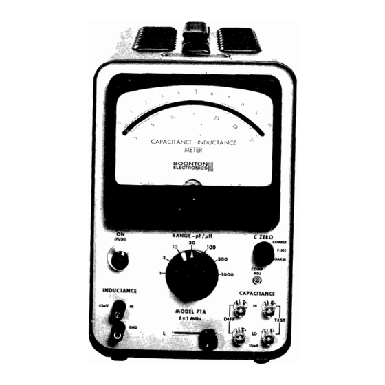
SECTION II General Description Model The Model 71A provides instant, direct-reading, three-terminal capacitance measurements and two-terminal inductance measure ments at 1 MHz. The measuring capabilities of 0 to 1000 pF and 0 to 1000 are each covered in 7 ranges in a 1-3-10 sequence. -
Page 8: Location Of Controls And
Location of Controls and Adjustments, Model 71 AR 26 INDUCTANCE ZERO STANDARD CAPACITOR SWITCH COMMON GROUND CONNECTION FOR DC OUTPUTS 15 t.l MEGOHM RESISTOR 17 DC OUTPUT CONNECTION FOR RECORDER, X·Y PLOTTER Remove for dvm's having 1 Ma input resistance >1 V fnrJnads >10 M!l LEVEL ADJUSTMENT FOR DC OUTPUT FOR DIGITAL... -
Page 9: Explanation Of Controls And Adjustments
2.5 Explanation of Controls and Adjustments 2.5.1 Front Panel, Models 7lA and 71AR pF!~: RANGE - Seven-position switch selects measuring ranges having full scale values of 1, 3, 10, 30, 100, 300, or 1000, with units of measurement being either picofarads or microhenries, as determined by the position of the "L/C"... - Page 10 (c) -Measuring a standard capacitor. (d) Testing a specimen having markedly different "HI"-to-ground capacitance than those tested previously with a given connection system (as caused by considerable differences in internal construction, encasing, or terminations). CAPACITANCE TEST: BNC connectors for the test specimen. Measurements may be made either locally or remotely by means of coaxial cables.
- Page 11 mente with varying meter readings, this emf may show up as slight irregularities in the dc output: switching the meter off eliminates this. In addition, switching the meter off eliminates needless wear of the meter movement when the dc output is used for widely varying test values. (In the Model 71A, this function is performed by the rear! panel "METER ON/OFF"...
- Page 12 CAL 2: Calibration adjustment for low Q measurements. For calibration procedures, see paragraph 3.10. 1000 pF ZERO: Zero adjustment for 1000 pF range. Once set on initial installation, this control will rarely need re adjustment. However, since the setting of this control is vital to proper operation for either capacitance or induc ...
-
Page 13: Operating Instructions
SECTION III Operating Instructions Initial Installation 3.1.1 Unpacking unpacking~ inspect the instrument for possible damage in damaged~ transit. If the instrument is contact your local Sales Engineering Representative or the factory (see title page for factory address) for further instructions. If no damage is found~... - Page 14 range~ With the instrument on the 1 pF and no specimen connected to the "TEST" terminals, set the indicator to about of full scale using the front panel "c ZERO" control. Adjust the front panel "COMP ADJ" control "c for a peak reading. (Readjust the ZERO"...
-
Page 15: Local Capacitance Measurements
capacitance Measurements With the front panel IIL-C II selector in the "C II position~ Models 71A and 71AR measure the "direct" capacitance of the test specimen. (The instruments ignore stray capacitance from the "LO" post to ground. Up to about 100 pF of capaci tance from the "HI"... - Page 16 3.3.2.1 111000 pF ZERO" Adjustment panel. 111000 pF ZERO" control is located at the rear Its setting is checked by switching to the 1000 pF range and, with no specimen attached at the IITEST terminals, observing the rest position of the pointer. If it does not read zero, follow the adjustment procedure outlined in paragraph 3.1.4,...
- Page 17 those to be measured. If no connectors are to be used, insert the leads of the specimen in the center conductors of the "TEST" posts. (b) Set the "RANGE" selector to the lowest range on w.mch a reading of approximately 75% of full scale is possible.
-
Page 18: Remote Capacitance Measurements
3.4 Remote Capacitance Measurements 3.4.1 Connections for Remote Measurements m~cted test specimen or a test fixture to the "TEST" terminals by coaxial cables. RG-62 is particularly recommended for this purpose because its low capacitance. To minimize errors in measurement resulting from the series inductance of the coaxial cable, the length of each of the two cables should be less than approximately feet on the... - Page 19 (c) Adjust the "CaMP ADJ" control for a maximum "e reading. (Readjust the ZERO" control to keep deflections on scale if required). peaking~ (d) After zero the pointer using the "c ZERO" control. adjusted~ Once the "CaMP ADJ" control need not be re adjusted for some time (although periodic checking during extended periods of operation is advisable) unless some change in either the connection system or...
- Page 20 fixture to be used in subsequent measurements should be attached for this adjustment.) "c with the 111000 pF ZERO" and ZERO" controls properly set, the instrument will be correctly zeroed for .all ranges, assuming the "COMP ADJ II control is properly adjusted.
- Page 21 CORRECTION FOR ERROR IN CAPACITANCE MEASUREMENT OWING TO SERIES INDUCTANCE RG-62/U CONNECTING CABLES HAVING COMBiNED LENGTH OF 1 FOOT to-' (SEE IMPORTANT NOTES BELOW) 1000 pF <C( , / ' 100pF <C( 0.. <C( 10pF 0-0001 pF O.OOlpF O-OlpF O·lpF 10pF SUBTRACT pF FROM CAPACITANCE READING FOR EACH FOOT OF...
-
Page 22: Differential Capacitance Measurements
from approximately 10 pF to 1000 pF. Because this correc tion factor is very nearly a direct function of cable length, for small corrections (10% or less), the correction required for pairs of other lengths can be readily computed. 3.5 Increasing the Capacitance Measuring Range The upper capacitance limt of 1000 pF may be increased by a factor of up to approximately 10 (to O.Oll-LF) by use of the... -
Page 23: Extending The Range Of The
for connection. Samples connected for differential measure ment may both be biased, since any voltage applied to the dc bias input appears across both the "TEST" and "DIFF" terminals. Remote differential measurements may be made by connecting the specimens to the "TEST" and "DIFF" terminals with coaxial cables. The "COMP ADJ"... -
Page 24: Capacitance Test Signal
In any case, the capacitance standard used must be a three-terminal device capable of operation at 1 MHz. The Boonton Electronics Model 7l-1A Capacitance Standard is designed specifically for use with the Model 7lA and is available as a separate accessory. - Page 25 WITH VOLTAGE RATING> E NOTE: LI03 MAY BE USED FOR LI03 MAY BE ORDERED FROM TO RESONATE IMHz. >200K --150)/H; 0.>200) &. Q", $1.50 BOONTON ELECTRONICS CORP., PART NO. 400124; PRICE 0.002 SECONDS. i MININU~ EACH ORDER \5.00. " ,.- CURRE L1I4ITIN...
- Page 26 references traceable to the National Bureau of Standards. It provides a particularly convenient means for checking the calibration of the Model 71A for both high and low 0 measurements. (0=3) 3.10.2 Calibration Check of the Model 71A with the Model 71-1A Standard capacitor (a) Remove all cables and adapters from the "TEST"...
- Page 27 added for the low Q check. However .. if it is necessary to use this method .. it is suggested that the capacitance stand ard be in the order of 100 pF and that the capacitance of the resistor be assumed to be 0.5 pF. This also has the advantage of requiring a resistor of sufficiently low value (approximately 5000 ohms) so that the effective 1 Mc resist ...
- Page 28 (1) removed~ With the shunting resistor set the rear panel IICAL 1" adjustment so that the meter reads the value of the standard. (2) Replace the shunting resistor and adjust "CAL 2" so that the meter reads the value of the stand ard plus the capacitance of the resistor.
-
Page 29: Connection For Inductance
3.11 Inductance Measurements 3.11.1 General with the "L/C" selector in the "L" position the Models 7lA and 7lAR measure two-terminal inductance. It will be noted that with the "L" position, the normal resting place of the indicator, with no specimen connected to the "INDUCTANCE" terminals, is at the extreme right, above full scale;... -
Page 30: Dc Output
3.14 DC output 3.14.1 General A dc analog of the measured capacitance or inductance value is available in two modes (REC and DVM) as selected by con nections at the rear panel. The output is valuable for such recorder~ plotter~ uses as application to a digital volt... - Page 31 3.15 "METER ON/OFF" switch In cases where tests are being made at high speed in con vo1tmeter~ com~arator junction with a digital voltage other external monitor~ the meter should be switched off by means of the rear panel "METER-OFF" switch to avoid possible interaction caused bya small counter-emf from the moving coil of the meter.
-
Page 32: Figure
CONNECTION ERROR RESULTING FROM 3 INCH LEADS OJ-..I OF NO.20 WIRE SPACED 3/4 I NCHES APART I--' >' "" 'I'\. 0:::: 0:::: 1\." 'I.. " 'I.. TOTAL ERROR ' I ..l/.' "" " ERROR OWING TO LEAD ERROR OWING TO LEAD C~PACITANCE (L%O.125~H) (C::::O.2 pF) - Page 35 SECTION IV List of Replaceable Parts - Mode Is 71 A-71 AR BEC Part No. Description Reference 230,116 200 V 0.1 }-IF Capacitor C101 275,138 1.8-8.7 pF Yare CI02 200,035 500 V 91 pF C103 200,002 500 V 120 pF CI03* 275,139 Yare...
- Page 36 BEC Part No. Description Reference 224,118 500 V 0.02 C-40-4 Capacitor 224,118 500 V 0.02 J-lF C405 224,118 500 V 0.02 llF C406 224,114 500 V 0.001 llF C407 283,130 10 llF C408 283,153 20 llF C409 234,027 200 V 0.01 llF C410 283,175...
- Page 37 Part No. Description Reference 1/2 W Resistor R211 301,147 1/2W R212 301,079 1/2 W R213 1/2W 301,087 R214 301,152 1/2W 510 K R215 315,067 1/4W R216 301,077 1/2W R217 301,123 33 K 1/2 W R218 301,121 27 K 1/2 W R219 470 n 1/2W...
- Page 38 BEC Part No. Description Reference 301,090 1/2W 1.3K Resistor R515 315,413 12.1 K 1/2W R516 301,160 T.1M 1!2W R517 315,023 lOOK 1/2W R518 311,115 25 K Potentiometer R519 315,418 20 K 1!2W Resistor R520 315,411 1/2W 10 K R521 Factory Selected R522 Factory Selected R523...
- Page 39 BEC Part No. Description Reference 400,120 1 pH Inductor L201 400,095 1 mH L202 400,117 105 to 200 pH L203 400,117 105 to 200 pH L204 400,118 220 pH L205 400,118 220 pH L206 400,095 L207 400,176 100 pH L208 400,176 200k 100 pH...
Need help?
Do you have a question about the 71A, 71AR and is the answer not in the manual?
Questions and answers