Table of Contents
Advertisement
DMX 512 CONTROLLER SERIES
This product manual contains important information about the safe installation and
use of this projector. Please read and follow these instructions carefully and keep this
manual in a safe place for future reference.
Notes :
Notes :
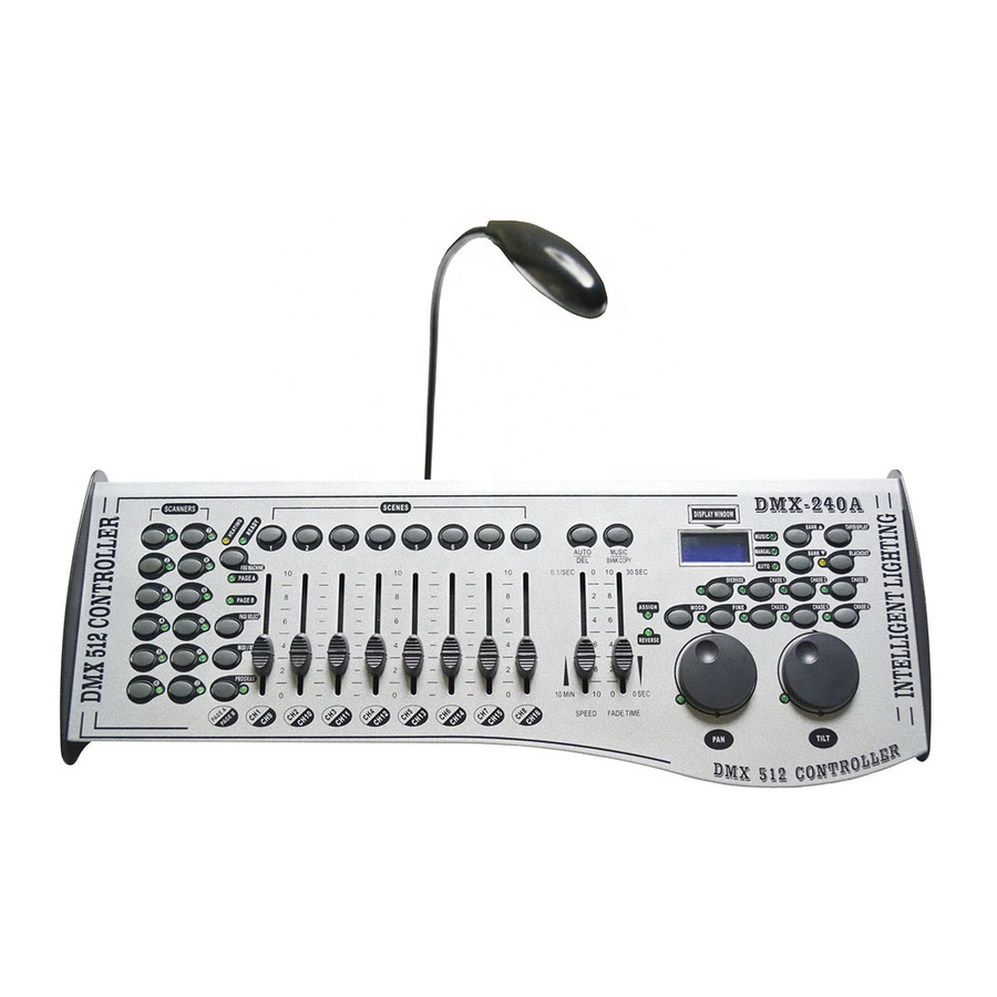
DMX-240A With Pan/Tilt Wheels
DMX-240A With Pan/Tilt Wheels
DMX-240B With Joystich
DMX-240B With Joystich
USER MANUAL
USER MANUAL
DMX-240A
DMX-240B
Advertisement
Table of Contents

Summary of Contents for Intelligent lighting DMX-240A, DMX-240B
- Page 1 DMX 512 CONTROLLER SERIES DMX-240A DMX-240B USER MANUAL USER MANUAL This product manual contains important information about the safe installation and use of this projector. Please read and follow these instructions carefully and keep this manual in a safe place for future reference. Notes : Notes : DMX-240A With Pan/Tilt Wheels...
-
Page 2: Table Of Contents
DMX 512 CONTROLLER SERIES Content Before you begin What is included..................Unpacking instructions ................Safety instructions ..................Installation Features ....................General overview ..................Product overview (front) ................Product overview (rear panel) ..............Common terms ................... 3. Operating instructions 3.1 SETUP .............. -
Page 3: What Is Included
DMX 512 CONTROLLER SERIES 1.1 What is included 1.1 What is included 1) DMX-240A controller 2) DC 9-12V 500mA, 90V~240V Power Adapter 3) Manual with warranty card 1.2 Unpacking Instructions Unpacking Instructions Immediately upon receiving a fixture, carefully unpack the carton, check the contents to ensure that all parts are present, and have been received in good condition. -
Page 4: General Overview
2.2 General Overview 2.2 General Overview * The DMX-240A is a universal intelligent lighting controller. It allows the control of 12 fixtures composed of 16 channels each and up to 240 programmable scenes. Six chase banks can contain up to 240 steps composed of the saved scenes and in any order. - Page 5 DMX 512 CONTROLLER SERIES Item Button or Fader Function Scanner select buttons Fixture selection Scanner indicator LEDS Indicates the fixtures currently selected Universal bump buttons representing scene Scene select buttons location for storage and selection For adjusting DMX values, Ch 1~8 can be adjusted immediately after pressing the respective scanner Channel faders select button, Ch 9~16 after pressing the Page...
- Page 6 DMX 512 CONTROLLER SERIES Item Button or Fader Function This will adjust the hold time of a scene or a step Speed fader within a chase Also considered a cross-fade, sets the interval Fade-Time fader time between two scenes in a chase Activates 16 bit control of the wheel, movement will be in extremely small increments.
-
Page 7: Product Overview (Rear Panel)
DMX 512 CONTROLLER SERIES 2.4 Product Overview (rear panel) 2.4 Product Overview (rear panel) DMX OUT DMX IN MIDI DMX OUT DC INPUT LAMP POWER AUDIO MACHINE 1=Ground 1=Ground 2=Data + 3=Data + DC 9V-12V 0.1-1VP-P 300mA min DMX Polarity select Item Button or Fader Function... -
Page 8: Common Terms
3.1.1 SETTING UP THE SYSTEM Plug the AC to DC power supply to the system back panel and to the mains outlet. 2) Plug in your DMX cable(s) to your intelligent lighting as described in the fixtures respective “ ”... -
Page 9: Fixture Addressing
3.1.3 WHEEL ASSIGNMENT 3.1.3 WHEEL ASSIGNMENT Because not all intelligent lighting fixtures are alike or share the same control attributes, the DMX-240A allows the user to assign the wheel the correct pan and tilt channel for every individual fixture including 16 bit channel assignments. It also allows the user to re-assign physical faders to fixture DMX channels so that the user can combine or unify control of similar or the same attributes across different types of fixtures. -
Page 10: Review Wheel Assignment Or Reverse
DMX 512 CONTROLLER SERIES Action : Action : Notes : Notes : 5) Press the TAP/DISPLAY button to switch You can re-assign the DMX channel to all controller pages fader channels. press and hold MODE button,then press the SCENES buttons to select the DMXchannel.All LEDs will blink. Press and hold FINE &... -
Page 11: Reverse Channel Output
DMX 512 CONTROLLER SERIES 3.1.6 REVERSE CHANNEL OUTPUT 3.1.6 REVERSE CHANNEL OUTPUT Action : Action : Notes : Notes : press and hold the PROGRAM button until the led You can permanently reverse the output of any given blinks channel on the controller. 2) Press and hold FINE &... -
Page 12: Review Scene Or Chase
DMX 512 CONTROLLER SERIES 3.2.2 REVIEW SCENE OR CHASE 3.2.2 REVIEW SCENE OR CHASE This instruction assumes that you have already recorded scenes and chases on the controller. Other wise skip section and go to programming. Action : ( Action : ( Notes : Notes : SCENE Review) -
Page 13: Running A Program
DMX 512 CONTROLLER SERIES 3.3.3 RUNNING A PROGRAM 3.3.3 RUNNING A PROGRAM Action : Action : Notes : Notes : BANK UP/DOWN buttons to change Program Deselect Blackout if LED is lit. banks if necessary. Press the AUTO DEL button repeatedly until the AUTO LED turns on. -
Page 14: Chase Programming
DMX 512 CONTROLLER SERIES Chase Programming Chase Programming A chase is created by using previously created scenes. Scenes become steps in a chase and can be arranged in any order you choose. It is highly recommended that prior to programming chases for the first time;... -
Page 15: Edit Chase (Copy Scene Into Chase)
DMX 512 CONTROLLER SERIES 3.4.5 3.4.5 EDIT CHASE (COPY SCENE INTO CHASE) EDIT CHASE (COPY SCENE INTO CHASE) Action : Action : Notes : Notes : Press and hold the PROGRAM button to enter programming mode. Press the desired CHASE button. -
Page 16: Delete All Chase Programs
DMX 512 CONTROLLER SERIES 3.4.9 3.4.9 DELETE ALL CHASE PROGRAMS DELETE ALL CHASE PROGRAMS CAUTION! This procedure will result in irrevocable loss of chase step memory. The individual scenes and program banks will be preserved. Action : Action : Notes : Notes : Turn OFF controller. -
Page 17: Delete A Scene
DMX 512 CONTROLLER SERIES 3.5.3 3.5.3 DELETE A SCENE DELETE A SCENE Action : Action : Notes : Notes : Press and hold the PROGRAM button to enter When deleting a scene the physical location is not programming mode. removed, however, all 192 DMX channels available to the scene will be set to value 0. -
Page 18: Blackout
DMX 512 CONTROLLER SERIES 3.6.4 3.6.4 BLACKOUT BLACKOUT Blackout button brings all lighting output to 0 or off. Midi Operation Midi Operation The controller will only respond to I commands on the MIDI channel which it is set to full stop. All MIDI control is performed using Note on commands. -
Page 19: Appendix
DMX 512 CONTROLLER SERIES 4 APPENDIX DMX Primer There are 512 channels in a DMX-512 connection. Channels may be assigned in any manner. A fixture capable of receiving DMX 512 will require one or a number of sequential channels. The user must assign a starting address on the fixture that indicates the first channel reserved in the controller. -
Page 20: Dmx Dipswitch Quick Reference Chart
DMX 512 CONTROLLER SERIES 4.3 DMX Dipswitch Quick Reference Chart 4.3 DMX Dipswitch Quick Reference Chart DMX Address Quick Reference Chart DMX Address Quick Reference Chart Dip Switch Position DMX DIP SWITCH SET 0=OFF 1=ON X=OFF or ON 128 160 192 224 256 288 320 352 384 416 448 480 129 161 193 225 257 289 321 353 385 417 449 481 130 162 194 226 258 290 322 354 386 418 450 482 131 163 195 227 259 291 323 355 387 419 451 483... -
Page 21: Technical Specifications
DMX 512 CONTROLLER SERIES 4.4 Technical Specifications Weight........................... 3.5 Kg Operating Range..................DC 9V-12V 500mA min Maximum ambient temperature..................45 C Data input .................. locking 3-pin XLR male socket Data output ................locking 3-pin XLR female socket Data pin configuration ..............pin 1 shield, pin 2 (-), pin 3 (+) Protocols......................DMX-512 USITT Protocols......................DMX-512 USITT 20/20...
Need help?
Do you have a question about the DMX-240A, DMX-240B and is the answer not in the manual?
Questions and answers