Baxi Combi 105 HE Installation & Servicing Instructions Manual
Gas fired wall mounted condensing combination boiler
Hide thumbs
Also See for Combi 105 HE:
- Installation & servicing instructions manual (60 pages) ,
- User operating instructions manual (14 pages) ,
- User's operating instructions & important warranty information (12 pages)
Table of Contents

Related Manuals for Baxi Combi 105 HE


Summary of Contents for Baxi Combi 105 HE
- Page 1 Installation & Servicing Instructions Baxi Combi 105 HE Gas Fired Wall Mounted Condensing Combination Boiler These instructions include the Benchmark Commissioning Checklist and should be left with the user for safe keeping. © Baxi Heating UK Ltd 2007...
-
Page 2: Table Of Contents
UK and to encourage the regular servicing of all central heating systems to ensure safety and efficiency. © Baxi Heating UK Ltd 2007 All rights reserved. No part of this publication may be reproduced or transmitted in any form or by any means, or stored in any... - Page 3 CORGI is written onto the Benchmark Checklist CORGI will record the data and LABC will record the data will send a certificate of and will issue a compliance to the property certificate of compliance © Baxi Heating UK Ltd 2007...
-
Page 4: Legislation
BS 7074 Expansion vessels and ancillary equipment Notified Body 0051. for sealed water systems. BS 7593 Treatment of water in domestic hot water central heating systems. Product/Production certified by: Notified Body 0086. For GB/IE only. © Baxi Heating UK Ltd 2007... - Page 5 If at any time when installing the boiler you feel that you may have injured yourself STOP !! DO NOT ‘work through’ the pain - you may cause further injury. IF IN ANY DOUBT DO NOT HANDLE OR LIFT THE BOILER - OBTAIN ADVICE OR ASSISTANCE BEFORE PROCEEDING !! © Baxi Heating UK Ltd 2007...
-
Page 6: Introduction
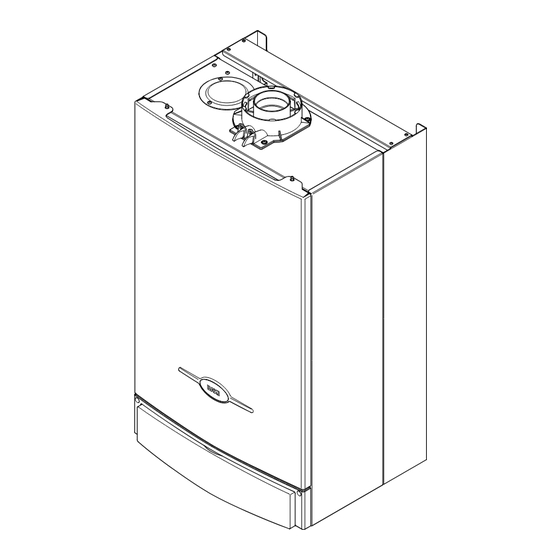
1.0 Introduction Description Case Front Panel 1. The Baxi Combi 105 HE is a fully automatic gas fired wall mounted condensing combination boiler. It is room sealed and fan assisted, and will serve central heating and mains fed domestic hot water. -
Page 7: General Layout
Fault on Central Heating Sensor Power On Domestic Hot Water Mode Central Heating Mode Burner On When neons 24 to 29 are constantly illuminated, they indicate the temperature of the central heating water. Reset © Baxi Heating UK Ltd 2007... -
Page 8: Appliance Operation
1. With the selector switch (see Section 2.1) in either the central heating or central heating and domestic hot water position the pump will automatically operate for 1 minute in every 24 hours to prevent sticking. Fig. 3 © Baxi Heating UK Ltd 2007... -
Page 9: Technical Data
Internal Fuse Rating Fuse 2A Fast Blow to BS 4265 Pump - Available Head SEDBUK Declaration For Combi 105 HE The seasonal efficiency (SEDBUK) is 87.3% (89.4% LPG) Band B This value is used in the UK Government’s Standard Assessment Procedure (SAP) for energy rating of dwellings. -
Page 10: Dimensions And Fixings
28mm Condensate Drain 65 mm 65 mm 65 mm 65 mm 65 mm Heating Heating Domestic Hot Cold Water Pressure Relief Return Valve Flow Water Outlet Inlet Inlet (22mm) (22mm) (15mm) (22mm) (15mm) (15mm) © Baxi Heating UK Ltd 2007... -
Page 11: System Details
6.0 System Details Information 1. The Baxi Combi 105 HE Condensing Combination Boiler is ‘Water Byelaws Scheme - Approved Products’. To comply with the Water Byelaws your attention is drawn to the following installation requirements and notes (IRN). a) IRN 001 - See text of entry for installation requirements and notes. - Page 12 3. The discharge must not be above a window, entrance or other public access. Consideration must be given to the possibility that boiling water/steam could discharge from the pipe. © Baxi Heating UK Ltd 2007...
- Page 13 1. If the area of the installation is recognised as a HARD WATER AREA then a suitable device should be fitted to treat the mains water supply to the boiler. Contact your Water Distribution Company for advice on suitable devices. © Baxi Heating UK Ltd 2007...
-
Page 14: Site Requirements
For Servicing Purposes heat exchanger. This should be considered when siting the appliance and in the event of any subsequent alteration in the area of installation. 5mm Min In Operation Fig. 9 © Baxi Heating UK Ltd 2007... - Page 15 Connection may be via a fused double-pole isolator with a contact separation of at least 3mm in all poles and servicing the boiler and system controls only. Fig. 10 Gas Service Cock © Baxi Heating UK Ltd 2007...
- Page 16 & vent pipe ii) via an internal discharge branch (e.g. sink waste) 500mm min iii) to a drain or gully iv) to a purpose made soakaway Holes in the soak-away must face away from the building © Baxi Heating UK Ltd 2007...
- Page 17 Top View Rear Flue any opening windows or doors (see Fig. 12 Section 9.0). Property Boundary Line Air Inlet Opening Window or Door 100mm Fig. 12a MIN. Likely flue positions requiring Fig. 11 a flue terminal guard © Baxi Heating UK Ltd 2007...
-
Page 18: Flue Options
8.0 Flue Options Horizontal Flue Systems 1. The Baxi Combi 105 HE can be fitted with either horizontal, vertical or twin flue systems as illustrated. 2. The standard flue is suitable only for horizontal applications. 3. Maximum permissible equivalent flue lengths are:-... - Page 19 This bend is equivalent to 1 metre Equivalent Length Air Duct = 6.5m FLUE DUCT Equivalent Sub total Length Value fittings/pipes 1m extension 5.0m 135°bend 0.5m 0.25m 91.5°bend 0.5m 1.0m Equivalent Length Flue Duct = 6.5m © Baxi Heating UK Ltd 2007...
- Page 20 FLUE GROUP A, N, Vertical Flue Kits Vertical flue terminal 5111078 (use with 5111070) Vertical flue terminal 5118576 Lead tile 25°/45° 246141 Lead tile 35°/55° 246142 Roof cover plate 246143 Flat roof flashing 246144 © Baxi Heating UK Ltd 2007...
- Page 21 5. Using the screws previously removed secure the inlet adaptor to the top panel. 6. Continue to fit the twin flue system. Air Duct Adaptor Gasket Restrictor Position of Restrictor Gasket © Baxi Heating UK Ltd 2007...
- Page 22 8.10 Flue Deflector (Fig. 13a) 1. If required a flue deflector is available from your Baxi stockist. 2. Push the flue deflector over the teminal end and rotate to the Fig. 14 optimum angle for deflecting plume. Secure the deflector to the terminal with screws provided.
-
Page 23: Plume Displacement
Installation & Servicing Instructions and BS5440 Pt. 1. It is NOT necessary to fit a terminal guard over the air inlet or the plume outlet. © Baxi Heating UK Ltd 2007... - Page 24 0.5 Additional Accessories metres long. A - 93° Elbow 5117381 B - 45° Elbow (Pair) 5117382 Fig. 18 C - 1 metre 60Ø Extension 5117380 © Baxi Heating UK Ltd 2007...
- Page 25 14. Fit the 93° elbow/plume outlet and secure with the two remaining screws supplied. Ensure the plume outlet is at least 45° to the wall and that the ‘peak’ is uppermost Fig. 24 (Fig. 24). © Baxi Heating UK Ltd 2007...
- Page 26 25. All other minimum & maximum dimensions must be adhered to, and the air inlet positioned such that it will not be subjetc to rain entry. Fig. 28 70° Concentric Flue Length (shown end-on) Outlet Spigot Fig. 29 © Baxi Heating UK Ltd 2007...
-
Page 27: Installation
2. Stand the boiler on its base by using the rear lower edge as a pivot. NOTE: A small amount of water may drain from the boiler in the upright position. Fig. 31 Central Heating Return © Baxi Heating UK Ltd 2007... - Page 28 21.5mm ( in) plastic overflow Fig. 33 pipe which should generally discharge internally into the household drainage system. If this is not possible, discharge into an outside drain is acceptable. Discharge Pipe © Baxi Heating UK Ltd 2007...
- Page 29 This dimension will be known as ‘X’ (Fig. 36). 4. To dimension ‘X’ add 50mm. This dimension to be Wall Thickness known as ‘Y’. IMPORTANT: Check all dimensions before cutting. Flue Elbow Adaptor Fig. 35 Wall Thickness Fig. 36 © Baxi Heating UK Ltd 2007...
- Page 30 Fig. 38 11. Fit the flue trim if required, and if necessary fit a terminal guard (see Section 8.8 & 8.9). VERTICAL FLUE 1. Only a flue approved with the Baxi Combi 105 HE can be used. Flue Elbow Fig. 39...
- Page 31 - black Flame Sensing Electrode and include checks for Ground Continuity, r - red Hydraulic Differential Pressure Switch g - green Resistance to Ground, Short Circuit and Polarity. DHW Flow Priority Microswitch Fig. 44 © Baxi Heating UK Ltd 2007...
-
Page 32: Commissioning The Boiler
OFF position and then Selector Switch back to either ( ) or ( ) (Fig. 47). Pressure Gauge Fig. 46 Reset Power On Neon Central Heating Hot Water Temperature Control Temperature Control Fig. 47 © Baxi Heating UK Ltd 2007... - Page 33 14. Once the pressure has been set turn the boiler off Fig. 51 and disconnect the pressure gauge. 15. Tighten the pressure test screw and refit the modulator to the valve. Reassemble in reverse order. © Baxi Heating UK Ltd 2007...
-
Page 34: Completion
I.S. 813 “Domestic Gas Installations”. This is in addition to the Benchmark Commissioning Checklist. 5. Hand over the Users Operating, Installation and Servicing Instructions, giving advice on the necessity of regular servicing. Facia Panel Fig. 52 © Baxi Heating UK Ltd 2007... -
Page 35: Servicing The Boiler
10. Remove the four screws securing the combustion Sensing box door and remove the door (Fig. 54). Tubes Ease Fan Spigot Outlet Pipe Clamps Inwards Fig. 55 Fan Spigot Outlet Pipe Combustion Box Door Fig. 54 Inner Door Panel © Baxi Heating UK Ltd 2007... - Page 36 26. Complete the relevant Service Interval Record section of the Benchmark Commissioning Checklist at the rear of this publication and then hand it back to the user. Inlet/Return Manifold © Baxi Heating UK Ltd 2007...
-
Page 37: Changing Components
3. Remove the two screws holding the pressure switch to the bracket on the combustion box top panel. 4. Fit the new pressure switch and reassemble all components in reverse order of dismantling. Fan Hood Fig. 63 Spring Washer Securing Screw © Baxi Heating UK Ltd 2007... - Page 38 Fit the electrodes to the new burner. 5. Engage the burner location brackets over the studs on the injector manifold and reassemble in reverse order. Burner Electrodes Electrode Grommets Fig. 65 Electrode Leads © Baxi Heating UK Ltd 2007...
- Page 39 4. The combustion box door insulation piece can be Rear Insulation replaced by carefully bending up the two retaining tabs. 5. Replace all insulation pieces and reassemble in reverse order. 13.8 Side Insulation Combustion Box Door Front Insulation Fig. 67 © Baxi Heating UK Ltd 2007...
- Page 40 3. Unscrew the sensor from the plate heat exchanger Plate Heat manifold. Examine the sealing washer,replacing if Exchanger necessary. 4. Reassemble in reverse order. The plug will only fit one way. Fig. 70 DHW Temperature Sensor © Baxi Heating UK Ltd 2007...
- Page 41 Pump Setting Automatic Air 2. Examine the ‘O’ ring seal, replacing if necessary, and Vent Fig. 72 fit it to the new automatic air vent. 3. Reassemble in reverse order. Pump Wiring Cover Fig. 73 © Baxi Heating UK Ltd 2007...
- Page 42 4. From underneath the boiler remove the screws securing the trap bracket. Bracket 5. Remove the trap and bracket from the boiler. Undo the locknut securing the trap to the bracket. Fig. 77 Condensate 6. Reassemble in reverse order. Drain Pipe © Baxi Heating UK Ltd 2007...
- Page 43 4. Remove the screws securing the switch to the facia panel. 5. Fit the new switch, ensuring that it is correctly Facia positioned and reassemble in reverse order. Selector Switch Knob Fig. 80 Temperature Control Knobs © Baxi Heating UK Ltd 2007...
-
Page 44: Diverter Valve Assembly
6. Remove the plastic disc and pushrod assembly. Plastic Disc Carefully examine the diaphragm and replace it if there is any damage. Pushrod 7. Reassemble in reverse order. Fig. 83 © Baxi Heating UK Ltd 2007... -
Page 45: Flow Regulator
2. Unscrew the venturi and remove the flow regulator. Flow Fig. 86 3. Check the cleanliness of the filter gauze, rinsing Regulator thoroughly in clean water as necessary. Fit the new Venturi flow regulator and reassemble in reverse order. Inlet/Return Manifold © Baxi Heating UK Ltd 2007... - Page 46 Unscrew the thermostat from the adaptor in the outlet elbow. 3. Reassemble in reverse order of dismantling. Ease Fan Spigot Outlet Pipe Clamps Inwards Fig. 88 Fan Spigot Outlet Pipe Overheat Thermostat © Baxi Heating UK Ltd 2007...
-
Page 47: Illustrated Wiring Diagram
Electrode Mains Input Link Fuse Overheat Stat Flue Stat Gas Valve Condensate Trap - brown - black - blue Reset Selector Switch Optional Timers - red - green - green / yellow - white © Baxi Heating UK Ltd 2007... -
Page 48: Fault Finding
Burner extinguishes neon flashing after 10 seconds Go to sections ‘I’ & ’L’ Burner output Go to section ‘G’ modulates until set temperature is reached Operation sequence correct Burner goes out Fan stops Pump stops © Baxi Heating UK Ltd 2007... - Page 49 Close DHW tap ‘G’ DHW flow valve senses no flow. Diverter valve spindle Primary water diverted to assembly faulty CH system. DHW flow switch released off Burner goes out Fan stops Pump stops Operation sequence correct © Baxi Heating UK Ltd 2007...
-
Page 50: Fault Finding Solutions
Cold resistance approx. 11K ohms (resistance reduces with increase in temp.) Fan connections correct at fan. PCB - A2 connector, is 230V Fan jammed or faulty winding Replace fan across terminals 5 & 7 Replace PCB © Baxi Heating UK Ltd 2007... - Page 51 230V at Main PCB - A1 1. Ignition electrode and lead connector across terminals 2. Electrode connection Replace gas valve 3 & 4. Check wiring 3. Spark gap and position electrical plug & igniter assembly © Baxi Heating UK Ltd 2007...
- Page 52 Press the reset button on the flue overheat thermostat. If the boiler does not relight or repeatedly cuts out. Check the operation of the flue system or replace the flue overheat thermostat © Baxi Heating UK Ltd 2007...
-
Page 53: Short Parts List
248042 E66 432 3-Way Valve Assy. 248061 342 571 Temperature Sensor 247394 E66 439 Safety Thermostat 248079 Gas Valve 5107339 5112380 E66 453 Pressure Gauge 248090 Igniter/Gas Valve Cable 5112385 Flue Overheat Thermostat 5112395 © Baxi Heating UK Ltd 2007... -
Page 54: Benchmark Checklist
5 1 1 1 8 0 9 BENCHMARK No. GAS BOILER COMMISSIONING CHECKLIST C O L L E C T I V E M A R K BOILER SERIAL No. NOTIFICATION No. CONTROLS To comply with the Building Regulations, each section must have a tick in one or other of the boxes TIME &... -
Page 55: Service Interval Record
SERVICE INTERVAL RECORD It is recommended that your heating system is serviced regularly and that you complete the appropriate Service Interval Record Below. Service Provider. Before completing the appropriate Service Interval Record below, please ensure you have carried out the service as described in the boiler manufacturer’s instructions. - Page 56 A T r a d i n g D i v i s i o n o f B a x i H e a t i n g U K L t d Brooks House, Coventry Road, Warwick. CV34 4LL After Sales Service 08700 60 30 60 Technical Enquiries 08706 049 049 Website www.baxi.co.uk e&oe ompany Comp N 5111809 - Iss 5 - 3/07 © Baxi Heating UK Ltd 2007...
Need help?
Do you have a question about the Combi 105 HE and is the answer not in the manual?
Questions and answers