Table of Contents
Advertisement
Quick Links
Advertisement
Table of Contents

Subscribe to Our Youtube Channel
Related Manuals for Barco PDS


Summary of Contents for Barco PDS
- Page 1 rëÉêÛë=dìáÇÉ • Manual #: 26-1204000-00 • Revision: 00...
- Page 2 30 days after the transfer of risks. In the event of justified notice of compliant, Barco can repair the fault or provide a replacement at its own discretion within an appropriate period. If this measure proves to be impossible or unsuccessful, the purchaser can demand a reduction in the purchase price or cancellation of the contract.
- Page 3 Not included in the guarantee coverage are system failures which are attributed to programs or special electronic circuitry provided by the purchaser, e.g. interfaces. Normal wear as well as normal maintenance are not subject to the guarantee provided by Barco either.
- Page 4 To avoid fire hazard, use only the fuse having identical type, voltage rating, and current rating characteristics. Refer fuse replacement to qualified service personnel. aç=kçí=léÉê~íÉ=áå=bñéäçëáîÉ=^íãçëéÜÉêÉë To avoid explosion, do not operate this product in an explosive atmosphere. PDS • User’s Guide...
- Page 5 For more information about recycling of this product, please contact your local city office or your municipal waste disposal service. For details, please visit the Barco website at: http://www.barco.com/en/AboutBarco/weee qìêâÉó=oçep=`çãéäá~åÅÉ==...
- Page 6 Information Products” (Also called RoHS of Chinese Mainland), the table below lists the names and contents of toxic and/or hazardous substances that Barco’s product may contain. The RoHS of Chinese Mainland is included in the MCV standard of the Ministry of Information Industry of China, in the section “Limit Requirements of toxic substances in...
- Page 7 “Electronic Information Products Pollution Control Labeling Standard” of Chinese Mainland, marked with the Environmental Friendly Use Period (EFUP) logo. The number inside the EFUP logo that Barco uses (please refer to the photo) is based on the “Standard of Electronic Information Products Environmental Friendly Use Period”...
- Page 8 `Ü~åÖÉ=eáëíçêó The table below lists the changes to the PDS User’s Guide. Table 0-1. Change History Date ECP # Description Approved By Initial release September 21, 599163 R. Pellicano 2012 viii PDS • User’s Guide...
-
Page 9: Table Of Contents
PDS Front Panel........ - Page 10 Save Config ......52 Preview Menu (PDS 902 Only) ..... . . 53 Output Src.
- Page 11 Adding Units to the Unit List ....... . 91 Controlling Multiple PDS Units....... 92 Save Setup .
- Page 12 Communicating with PDS ........
- Page 13 DIAG ......... . 143 PDS • User’s Guide...
- Page 14 Contact Information ......... . . 150 PDS • User’s Guide...
-
Page 15: Chapter Structure
NK==fåíêçÇìÅíáçå få=qÜáë=`Ü~éíÉê This chapter is designed to introduce you to the PDS User’s Guide. Areas to be covered are: • Chapter Structure • How to Use This Guide • Conventions • About the PDS • Connectivity Diagram • Application Questions `Ü~éíÉê=píêìÅíìêÉ... - Page 16 From the Main Menu, select INPUT to display the Input Menu. Scroll to the Input Sizing line and press SEL to display the Input Sizing Menu. Scroll to the H Position line and press SEL to adjust the image’s horizontal position. PDS • User’s Guide...
-
Page 17: Overview
PDS accepts analog, DVI, and HD-SDI input sources and converts them to a wide variety of output formats. Output video is provided on analog and DVI connectors simultaneously. PDS also allows you to capture and store up to three images to be used as full-screen logos during the presentation. - Page 18 When an HDCP-compliant display is connected to the PDS, an HDCP “session” is created. In this session (which is transparent to the user), “keys” are exchanged between the source device (e.g., a Blu-Ray player) and the HDCP-compliant display.
-
Page 19: Connectivity Diagram
During this process, all PDS output connectors that are not HDCP-compliant are turned off, when the protected content is selected to be shown on those outputs. -
Page 20: Application Questions
• The PDS 902 connects to a Preview monitor via analog or DVI. • The PDS connects to a projector (or other target device) via analog or DVI. In Chapter 2, refer to the “Inputs Section” heading on page 10 for details on all inputs. -
Page 21: Pds Front Panel
OK==e~êÇï~êÉ=lêáÉåí~íáçå få=qÜáë=`Ü~éíÉê This chapter provides detailed diagrams of the PDS’s front and rear panels, along with comprehensive explanations of each. The following topics are discussed: • PDS Front Panel • PDS Rear Panel PDS • User’s Guide... -
Page 22: Display Section
2. Hardware Orientation PDS Front Panel map=cêçåí=m~åÉä The figure below illustrates the PDS front panel: Inputs PDS-701 Main Menu LOGO > In Auto Acquire Input >> Adjust BLACK TAKE Output >> Effects Figure 2-1. PDS Front Panel Display Section Take Button... - Page 23 Descriptions of each button and control are provided below: • The Menu Display is a 4-line x 20-character Vacuum Fluorescent Display (VFD) that shows all PDS menus and sub-menus. Brightness is adjustable. The following illustration shows a typical PDS menu. SE TUP >...
- Page 24 If a DVI signal is not present, the selection defaults to the analog signals that are on the DVI-I connector’s analog pins. Note that a customer- supplied DVI to HD-15 adapter is required to connect to the analog pins. PDS • User’s Guide...
- Page 25 Press TAKE to perform the transition to or from black. – If the transition is “to” black, the button lights solid when black is on Program. – If the transition is “from” black, the button turns off when the selected source is fully on Program. PDS • User’s Guide...
- Page 26 The TAKE button is also used to transition to/from black, when the “Black Auto Take” function is in the User Preference Menu. In Chapter 4, refer to the “User Preference Menu” section on page 58 for details on the User Preference Menu. PDS • User’s Guide...
-
Page 27: Pds Rear Panel
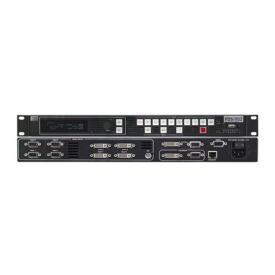
2. Hardware Orientation PDS Rear Panel map=oÉ~ê=m~åÉä The figures below illustrate the rear panels for PDS-902, PDS-901, and PDS-701: VIDEO INPUTS SERIAL Input 3 Input 4 Input 7 Input 8 Preview Input 8 Input 1 Input 2 Input 5 Input 6... - Page 28 109 for pinouts. DVI and Analog Inputs Four DVI-I connectors are provided on the PDS-902 and PDS-901, and two on the PDS-701, for both digital and analog inputs. Using the connector’s digital pins, an 8-bit digital input is supported.
-
Page 29: Safety Precautions
PK==fåëí~ää~íáçå få=qÜáë=`Ü~éíÉê This chapter provides detailed instructions for installing the PDS hardware. The following topics are discussed: • Safety Precautions • Unpacking and Inspection • Site Preparation • Rack-Mount Installation • Cable and Adapter Information • Signal Installation • Format Connection Table... - Page 30 If you find any shortages, contact your sales representative. The PDS shipping box contains the PDS unit, a power cord, and a CD. Once you have removed all the components from their packaging and checked that all the components are present, visually inspect the unit to ensure there was no damage during shipping.
- Page 31 3. Installation Cable and Adapter Information • Rack mount each PDS chassis from the front rack ears using four rack screws (not supplied). Rack threads may be metric or otherwise — depending upon the rack type. • Install the lower of the two mounting holes first.
- Page 32 Transformateur Graphique. On n'a pas besoin du controller usager pour la choix de la ligne de voltage. Warnung Das PDS gerät mu beim Anschlu an 240V ~ mit einer vom VDE auf 250V/10A geprüften Netzleitung mit einem Schukostecker ausgestattet sein.
-
Page 33: Signal Installation
3. Installation Signal Installation páÖå~ä=fåëí~ää~íáçå The figure below illustrates a sample PDS system. Use this figure for reference during the signal installation process. Sample Source Input Sample Source Input Devices Devices Program * Preview output not available on PDS 701 or 901... -
Page 34: Format Connection Table
This completes system signal installation. Please continue with system setup, menu orientation and operations, as outlined in Chapter 4, “Operation” on page 23. cçêã~í=`çååÉÅíáçå=q~ÄäÉ Use the following table to connect various source formats to the PDS, using the analog HD- 15 connectors (on Inputs 1 through 4). Please note: •... - Page 35 (Chrom) H Sync V Sync Please contact Barco Technical Support for information on obtaining breakout cables. In Appendix C, refer to the “Contact Information” section on page 150 for details. PDS • User’s Guide...
- Page 36 3. Installation Format Connection Table PDS • User’s Guide...
-
Page 37: Control Overview
QK==léÉê~íáçå få=qÜáë=`Ü~éíÉê This chapter provides comprehensive menu descriptions and detailed operating instructions for the PDS. The following topics are discussed: • Control Overview • Power-Up Initialization • Button States • Quick Setup and Operations • Menu Tree • Using the Menu System •... - Page 38 The “version” line in the above menu shows the software version that is currently installed. This version number changes as software upgrades are released. When you first start up a PDS that has stored logos, a message like the one in the following PDS • User’s Guide...
-
Page 39: Button States
“Power-Up Initialization,” page 24.) Factory reset — If you are using the PDS for the first time, or if you are using a PDS that has just returned from another event, perform a full factory reset to restore system configurations. (This chapter, “Factory Reset... -
Page 40: Quick Setup And Operations
4. Operation Quick Setup and Operations Launch GUI — (Optional) If you want to run the system from the web-based GUI, ensure that Ethernet is connected between your PC and the PDS, then launch the GUI. (Chapter 5, “GUI Operations,” page 85.) Set output format —... -
Page 41: Menu Tree
4. Operation Menu Tree jÉåì=qêÉÉ The figure below illustrates the entire PDS menu tree. Please use this diagram for reference as you learn how to operate the system. Status M enu Setup M enu Input O utput Logo U ser P reference... - Page 42 4. Operation Using the Menu System rëáåÖ=íÜÉ=jÉåì=póëíÉã This section lists the rules and conventions for using PDS’s menu system. For reference, the figure below illustrates the Setup Menu: SE TUP > Inpu t >> Output >> Logo >> Figure 4-6. Setup Menu (sample) For all setup menus, please note the following important menu rules and conventions: •...
- Page 43 Throughout this chapter, entire menus will be shown for clarity — rather than a series of four-line sections. • If a value is displayed between brackets, (e.g., [SMPTE]) this indicates that the value can not be changed. PDS • User’s Guide...
- Page 44 Quick Function Reference nìáÅâ=cìåÅíáçå=oÉÑÉêÉåÅÉ Use the following table to quickly access the proper section for a specific function. Both hyperlinks and page numbers are provided. Table 4-1. PDS Quick Function Reference Table How to: Use the Following Section: Page Adjust background color...
- Page 45 4. Operation Quick Function Reference Table 4-1. PDS Quick Function Reference Table (Continued) How to: Use the Following Section: Page Set Auto Input Cfg mode Auto Input Cfg Set Auto Input Save mode Auto Input Save Set Auto Take mode...
- Page 46 4. Operation Quick Function Reference Table 4-1. PDS Quick Function Reference Table (Continued) How to: Use the Following Section: Page Use the Status Menu Status Menu Use the System Menu System Menu Use the User Preference Menu User Preference Menu...
-
Page 47: Status Menu
*Hact x Vact @ Vr* Asterisks. The format has been “best guessed.” [Hact x Vact @ Vr] Brackets. The exact table match has been saved. [*Hact x Vact @ Vr*] Brackets plus Asterisks. The best guessed format has been saved. PDS • User’s Guide... - Page 48 HDCP has been set to OFF within the HDCP menu under User Preference. • Next Input Format — Indicates the input formats on Program, in the form: Hact x Vact @ Vr Hz 1400x1050@59.94 Hz PDS • User’s Guide...
-
Page 49: Setup Menu
4. Operation Setup Menu pÉíìé=jÉåì After PDS initialization is complete, the Status Menu appears. This is the system’s top- level menu. Refer to the “Status Menu” section on page 33 for details. To display the Setup Menu from the Status Menu, press SEL. -
Page 50: Adjust On
While you are already in the Input Menu, press a different input button and TAKE it to Program. The fields update to reflect the values for the new input. Changing the parameters for one input does not affect the Note input configuration of the other inputs. PDS • User’s Guide... -
Page 51: Auto Acquire
When Auto Acquire is OFF, the system attempts to lock to the signal using the configuration defined in the File Association Menu for each input channel. If the input signal is too different from the saved configuration to be usable, the display indicates “Invalid Signal.” PDS • User’s Guide... - Page 52 YUV is SMPTE. • The Colorspace Menu allows selection between these two values when the input is analog (excluding CVBS, Y/C) or DVI. • When either the CVBS or Y/C input is selected, only [SMPTE] is shown. PDS • User’s Guide...
-
Page 53: Auto Acquire
When Auto Acquire is ON, and the input source is digital, the system uses the following search order: • Saved configuration files defined in the File Association Menu for each input channel • The user’s library of saved files PDS • User’s Guide... -
Page 54: Aspect Ratio
• When the Auto Acquire mode is ON, the PDS automatically detects and acquires the input video type and resolution (in most cases), and limits menu selections to those applicable to the detected video type. -
Page 55: Sizing Adjust
As you size, the PDS scales the input up to fit the selected aspect ratio. The maximum allowable H/V size is up to 33% of the input's Note corresponding active area. -
Page 56: Timing Adjust
• When 1:1 Sample is set to On, values are the true timing measurements for the analog RGB or YP inputs. • When 1:1 Sample is set to Off, values represent the oversampling factor being used. PDS • User’s Guide... - Page 57 Its value will always be shown in brackets. ^ÇàìëíáåÖ=p~ãéäÉ=mÜ~ëÉ The PDS has two A-to-D converters, which are referred to as Phase A and Phase B in the Timing Adjust Menu. The sample phase value of each scaler can be changed by the Auto Config menu option, or set to the default value of 0 (zero).
-
Page 58: Contrast
Each of the individual contrast and brightness settings operates in conjunction with the “global” contrast and brightness settings in the Input Menu. • (all values): -25.0% to +25.0% Adjustment range • (all values): 0.0% Default • Select Reset All to set all values back to their default settings. PDS • User’s Guide... -
Page 59: Processing
• Sync Selection — This function applies only to Analog RGB inputs. The PDS automatically selects the syncs for digital sources, composite, S-video, and inputs. For these inputs, the value field indicates [N/A]. The sync choices are Auto, H/V (horizontal/vertical sync), CSync (composite sync) and SOG (sync on green). -
Page 60: Save Config
Default: 128mV ^Äçìí=fåéìí=`çåÑáÖìê~íáçå=cáäÉë The PDS supports saving up to 64 input configuration files in non-volatile memory, each of which is available to the nine physical inputs (1 through 8 and SDI). Input configuration files contain settings that govern everything from pixel resolution to aspect ratio and color balance —... - Page 61 Resetting configuration parameters does not change the Note configuration file associated with the input — it simply assigns the restored parameters to the existing configuration file. The file number shown in the File Association Menu does not change. PDS • User’s Guide...
-
Page 62: Recall Config
When Auto Acquire is OFF, the system will use the configuration file defined in the File Association Menu, to the greatest extent possible. If the input does not have a saved configuration file, the PDS displays the “Invalid Signal” message and the video output is black. - Page 63 Figure 4-23. Deleting Input Configuration Message (sample) You can assign a configuration file to more than one input. If Important you do so, you must exercise caution when deleting the file, because it will be deleted for all inputs. PDS • User’s Guide...
-
Page 64: Output Menu
This line indicates the format in the following form: Hact x Vact @ Vr Hz The output format for the PDS can be set to any of the progressive outputs. The output format is not updated until SEL is pressed. - Page 65 V Position — This function is bracketed when V Size is at its maximum setting as governed by the currently selected output format. When you adjust V Size below its maximum value, this field becomes active, enabling you to adjust vertical PDS • User’s Guide...
-
Page 66: Save Config
When you perform the Save Config function, all configuration parameters from the Output Menu are saved in non-volatile memory. If you do not perform the function, output data will not be restored upon the next system power up. PDS • User’s Guide... -
Page 67: Output Src
(ESC) to continue operation without saving the changes. mêÉîáÉï=jÉåì=Emap=VMO=låäóF From the Output Menu, select Preview to configure the PDS’s Preview output. The Preview output allows you to view, resize, and otherwise adjust the input source before taking it to Program. You can preview each of the input sources (1 through 8, SDI and LOGO). - Page 68 Hact x Vact @ Vr Hz 1024x768@59.94 The output format for the PDS can be set to any of the progressive outputs. The output format is not updated until you press SEL. Note To make pixel-for-pixel adjustments, set the Preview and Program resolutions to be the...
- Page 69 After you make changes using the Preview Menu, use the Save function to store them in non-volatile memory. Your configuration parameters will then persist across power cycles. If you do not choose Save after making changes, you are prompted to do so with a PDS • User’s Guide...
- Page 70 Press SEL to save your changes. • Press ESC to continue without saving your changes. If you do not save your changes, your settings will not be restored the next time the system is powered up or the input is selected. PDS • User’s Guide...
-
Page 71: Logo Menu
Delete Logo — Choose this field and press SEL to delete the Logo from the selected memory register. The Delete Logo field does not appear if the Logo is pending or on Program. Refer to the “Using the Logo” section on page 78 for more information on using Logos. PDS • User’s Guide... -
Page 72: User Preference Menu
Standard Mix — When transitioning between inputs and the logo, or transitioning to/from black, the PDS functions as a seamless switcher. The transition interval is defined as the total time required to mix to the new source, or fade to/from black. -
Page 73: Auto Acquire
• When the Auto Acquire mode is ON, the PDS automatically detects and acquires the input video type and resolution (in most cases), and limits menu selections to those applicable to the detected video type. - Page 74 “Black” and “Gray.” This is a global setting. When set to Gray, you can clearly see the edges of an input, particularly when the input’s aspect ratio does not match the output’s aspect ratio. Note that the background selection persists between source changes. PDS • User’s Guide...
- Page 75 In 7 (DVI-I) — The default setting is OFF. • In 8 (DVI-I) — The default setting is OFF. In 7 and In 8 are not available for selection in PDS-701 units. Note To turn HDCP capability on or off, use the following procedure: On the Setup Menu, select User Preference.
- Page 76 When ON, regardless of the current menu, the Input Menu or Logo Menu will automatically be displayed when the associated button is pressed. • When OFF, menu context does not change when an Input or LOGO button is pressed. PDS • User’s Guide...
-
Page 77: System Menu
From the System Menu, select VFD Brightness to control the intensity of the front panel VFD (vacuum fluorescent display). • range: 1 - 8 (1 is the dimmest setting) Adjustment • Default: 5 It is recommend that you use a low intensity setting to avoid Note “burn-in” of the display. PDS • User’s Guide... - Page 78 Always consult with your network administrator to obtain valid Note IP, subnet mask and gateway addresses. When ON, the PDS queries the DHCP server for a valid IP address, and the Config Network field is hidden. • If the PDS finds a DHCP server and receives an IP address, the address is displayed.
- Page 79 Select (ESC) to exit the procedure without saving changes. In each case, system returns to the root menu. When Ethernet setup is complete, you can communicate with the PDS via the Ethernet port. In Appendix B, refer to the “Remote Commands”...
- Page 80 4. Operation Setup Menu • Remote Control — This function sets up the PDS for remote control. RE MOTE C O NT ROL > Un it ID 192.168.000.002 St atus Co nnect O F F Figure 4-44. Remote Control Submenu (sample) For complete details, see “Appendix...
- Page 81 The PDS’s EDID file is stored in non-volatile memory. This file is read by a computer's DVI graphics card during boot-up, when its DVI output is connected to a DVI-I input connector on the PDS system. The PDS must be powered on first for the EDID information to be read. The following functions are available: •...
- Page 82 E q u a l i z a t i o n Set to Def aul t Set to Ma xi m um Set to Min i mu m Figure 4-50. DVI Cable Equalizer Menu (sample) PDS • User’s Guide...
-
Page 83: Executive Mode
From the Setup Menu, choose the System Menu. Select Executive Mode. The following submenu appears: EX ECUT IVE MODE < S E L > = E n a b l e <ESC> = Cance l Figure 4-51. Executive Mode Menu (sample) PDS • User’s Guide... -
Page 84: File Association
— any setting you can change using the Input Menu. The PDS can store up to 64 input configuration files in non-volatile memory. Each time you press an input button, the PDS uses the configuration file associated with that input. -
Page 85: Temperature
Celsius and Fahrenheit. When the menu is displayed, temperature values update every 4 seconds. Note that the PDS measures the internal temperature for an “over-temp” condition every 5 minutes. If the system’s internal temperature exceeds 122° F (50° C), the following... -
Page 86: Save System State
4. Operation Setup Menu If you suspect a problem with the PDS, press SEL to run a series of internal diagnostic tests. The menu will report back “PASS” or “FAIL.” If the menu reports “FAIL,” contact Barco Customer Service. Note In Appendix C, refer to the “Contact... -
Page 87: In This Chapter
< E S C > = N o Figure 4-60. Factory Reset Menu This function enables you to reset the PDS to its factory default condition, in which all user- defined input, output and system configuration files are deleted. When the command is executed, a confirmation menu is shown. - Page 88 When "Reset All, Save EDID" is selected, the unit will return Note to a default configuration as noted above, with the exception of EDID, which will NOT be changed. cáêãï~êÉ=réÖê~ÇÉ=jÉåì For details about upgrading firmware, see “Upgrading Firmware” on page 93. PDS • User’s Guide...
-
Page 89: Using Inputs
“pending.” Press TAKE to transition the input to Program, using the current transition rate (as entered on the Setup Menu). Whenever TAKE is pressed, the PDS flip-flops sources in the Note Inputs Section. Refer to the “Flip-flop... - Page 90 4. Operation Using Inputs cäáéJÑäçé=jçÇÉ Whenever you press TAKE to mix between inputs (including the LOGO), the PDS automatically flip-flops inputs. Two actions occur when TAKE is pressed: • The blinking “next” source transitions to Program. Once it is fully on Program, the button lights solid.
- Page 91 (blinking) source will transition to program after TAKE is pressed. • When the system performs an Auto Acquire for Inputs 5 through 8, the PDS first checks for a DVI signal. If not found, the system looks for a valid analog signal.
-
Page 92: Using The Logo
The PDS can store up to three logos in non-volatile memory. The PDS enables you to transition to or from a full-screen logo, in the same way that you transition to or from video inputs. When you press TAKE, the system transitions the... - Page 93 The LOGO button blinks “slow” to indicate that a logo is pending, and the Logo Menu appears: L O G O > S e l e c t i o n L O G O 1 [ 1024x768] Figure 4-66. Logo Menu — Selecting a Logo PDS • User’s Guide...
- Page 94 > S e l e c t i o n [ L O G O 3 ] [1024x7 68] Figure 4-67. Logo Menu — Logo on Program When the system transitions to the logo, the PDS flip-flops Note sources in the Inputs Section. Refer to the “Flip-flop Mode”...
-
Page 95: Using Freeze
Press BLACK. The button blinks to indicate that a transition to/from black is pending. Press TAKE. The system transitions to/from black, at the current transition rate. Please note: If the transition is “to” black, the BLACK button lights solid when black is fully on Program. PDS • User’s Guide... - Page 96 If desired, you can transition to the pending source underneath black, by pressing TAKE in the normal manner, and then pressing BLACK to immediately fade up to the new source. PDS • User’s Guide...
-
Page 97: Using Front-Panel Lockout
4. Operation Using Front-Panel Lockout rëáåÖ=cêçåíJm~åÉä=içÅâçìí The PDS includes two front-panel lockout modes: • Full lockout mode, which locks the front panel from all source selections • Executive mode, which locks all front panel selections except the nine input buttons (1 through 8 and SDI) and LOGO. In executive mode, the user can transition from one input source to another without pressing TAKE. - Page 98 4. Operation Using Front-Panel Lockout PDS • User’s Guide...
-
Page 99: Gui Connection And Launch
RK==drf=léÉê~íáçåë få=qÜáë=`Ü~éíÉê This chapter provides connection, launch and operating instructions for the system’s web- based GUI, which enables you to perform all PDS setup and transition functions, just like the system’s “physical” front panel. The following topics are discussed: •... -
Page 100: Gui Operations On A Pc
The default IP address is 192.168.0.10. Note On your PC (or laptop), open up a web browser. In the browser’s address bar, enter the PDS’s IP address as shown in the following illustration. Figure 5-1. Address bar with sample IP address Avoid using leading zeros in the IP address. - Page 101 5. GUI Operations GUI Connection and Launch When the PC establishes communications with the PDS, several web pages are downloaded into the PC, and the PDS Home Page appears: Figure 5-2. PDS Home Page 10. Click the Control Application GUI link to launch the GUI. The GUI Status Menu page appears, as shown below: Figure 5-3.
- Page 102 The figure below illustrates a sample GUI screen, as seen on a PC: Figure 5-4. PDS PC GUI Setup Menu Running the PDS GUI is virtually identical to running the system from the physical front panel. The similarities are: •...
-
Page 103: Gui Operations On A Mobile Device
The figure below illustrates a sample GUI screen, as seen on a mobile device. It has the same controls as those for a PC, described in “GUI Operations on a PC” on page 88. Figure 5-5. PDS Cell-Phone GUI Setup Menu PDS • User’s Guide... -
Page 104: Multiple Unit Control Ui
After discovery and setup of the PDS units in the UI, one or more units can be enabled to accept source changes or transitions. After this is done, selection of any input, including Logo or initiation of a transition, will happen on the selected PDS units. - Page 105 ^ÇÇáåÖ=råáíë=íç=íÜÉ=råáí=iáëí Select the “Discover” tab (next to the “Edit” tab) in the upper right window of the PDS Multiple Unit Control UI. The PDS Discover Menu will appear. Figure 5-7. PDS Discover Menu Press the “Discover” button in lower left corner of this window. The UI will query the network and find all available PDS units.
- Page 106 The control section of the UI gives the operator control over the multiple PDS units. Each PDS in the unit list is represented with a status window. This window reports the Name of the PDS unit, what source is on Preview and Program, and whether the unit is currently connected to the network.
-
Page 107: Firmware Upgrade Overview
SK==réÖê~ÇáåÖ=cáêãï~êÉ få=qÜáë=`Ü~éíÉê This chapter provides detailed instructions for upgrading PDS system firmware. The following topics are discussed: • Firmware Upgrade Overview • Hardware Requirements • Firmware Requirements • Downloading Firmware via FTP or Web Site • Upgrading Firmware Using the USB Port •... - Page 108 Firmware Upgrade Overview cáêãï~êÉ=réÖê~ÇÉ=lîÉêîáÉï Firmware files for the PDS are loaded into the hardware at power-up. These files are stored in the unit’s onboard flash memory. The PDS’s system firmware can be easily upgraded using the steps described in the sections that follow.
-
Page 109: Via Ftp Site
To download firmware from the FTP site: Create a target folder on your PC or USB Flash drive (e.g., PDS). Ensure that your PC is connected to the internet. Log on to the FTP site using one of the following methods:... -
Page 110: Upgrading Firmware Using The Usb Port
PDS firmware can be downloaded from the FTP or Web site to a USB memory stick. This involves plugging the USB stick into the PDS, going to a menu in the PDS, and initiating the transfer of the file from the USB stick to the PDS. - Page 111 Flash drive into the PDS's USB port. To upgrade the PDS firmware via the USB port, use the following procedure: Insert the USB Flash drive into the PDS’s USB port. Select Firmware Upgrade from the Setup Menu. The Firmware Upgrade Submenu appears.
-
Page 112: Upgrading Firmware Using The Web Upgrade
When the file is loaded, the PDS powers down and reboots. réÖê~ÇáåÖ=cáêãï~êÉ=rëáåÖ=íÜÉ=tÉÄ=réÖê~ÇÉ `ÜÉÅâáåÖ=Ñçê=^î~áä~ÄäÉ=cáêãï~êÉ=réÖê~ÇÉë To determine whether a new version of the PDS firmware is available, use the following procedure: Verify that the PDS has internet access. Contact your system administrator if necessary. - Page 113 Press <SEL> to start the upgrade. A message will inform you to “Please wait...”. Ple ase wa it ..Figure 6-6. Upgrade Wait Message After the upgrade is finished, the PDS will automatically reboot. Re se tting ..Ple ase wa it Figure 6-7.
- Page 114 192.168.000.010, for example, type the address as shown in the preceding illustration, not as shown on the display. When the PC establishes communications with the PDS, several web pages are downloaded into the PC, and the PDS Home Page appears: Figure 6-9. PDS Home Page...
- Page 115 Click the Firmware Upgrade link to continue the upgrade process. The Select File page appears, as shown below: Figure 6-10. PDS Select File Page 10. Click the Browse button, and navigate to the folder on your PC where you saved the latest version of code.
- Page 116 If a problem was encountered during the process, click View Log File to display a text-based log of the upload procedure. If the upload was successful, click Restart PDS to complete the entire upgrade procedure. 14. Close your browser, and resume operations on the PDS.
- Page 117 6. Upgrading Firmware Upgrading Firmware Using the Web Upgrade qêçìÄäÉëÜççíáåÖ=bíÜÉêåÉí=`çããìåáÅ~íáçå Use the following steps to determine the IP address of the PDS, and establish proper communications: Power-up the PDS. Note the PDS’s current IP address: From the Status Menu, press SEL to display the Setup Menu.
-
Page 118: Upgrading Firmware
6. Upgrading Firmware Upgrading Firmware Using the Web Upgrade PDS • User’s Guide... - Page 119 ^K==péÉÅáÑáÅ~íáçåë få=qÜáë=^ééÉåÇáñ This appendix provides detailed technical specifications for the PDS. The following topics are discussed: • Input Specifications • Output Specifications • Physical and Electrical Specifications • Communications Specifications • Agency Specifications • Pinouts PDS • User’s Guide...
-
Page 120: Input Specifications
^K==péÉÅáÑáÅ~íáçåë Input Specifications fåéìí=péÉÅáÑáÅ~íáçåë= The table below lists PDS input specifications. Table A-1. PDS Input Specifications Parameter Detail Specification Inputs 1 - 4 Connector HD-15 VGA Format RGBHV / RGBS / RGsB computer video, YPbPr video (SD or HD), S-video, or composite video... - Page 121 ^K==péÉÅáÑáÅ~íáçåë Output Specifications PDS • User’s Guide...
-
Page 122: Physical And Electrical Specifications
^K==péÉÅáÑáÅ~íáçåë Physical and Electrical Specifications mÜóëáÅ~ä=~åÇ=bäÉÅíêáÅ~ä=péÉÅáÑáÅ~íáçåë= The table below lists PDS physical and electrical specifications. Table A-3. PDS Physical and Electrical Specifications Parameter Detail Specification Power Connector Standard IEC, integral on/off switch Power 100-240 VAC, 50-60 Hz Mechanical Chassis H: 1.75 inches (4.4 cm), 1 RU rack mount W: 17.00 in. -
Page 123: Pinouts
The table below lists Analog 15-pin D connector pinouts. Table A-6. Analog 15-pin D Connector Pinouts Signal Signal +5V DDC Power Green Blue DDC Data H Sync or C Sync Red return V Sync Green return DDC Clock Blue return PDS • User’s Guide... -
Page 124: Dvi-I Connector
T.M.D.S. Data 1+ T.M.D.S. Clock Shield T.M.D.S. Data 1/3 Shield T.M.D.S. Clock + T.M.D.S. Data 3- T.M.D.S. Clock - MicroCross Pins Analog Red Video Analog Horizontal Sync Analog Green Video Analog Common Ground Return Analog Blue Video PDS • User’s Guide... -
Page 125: Ethernet Connector
Table A-8. Ethernet Connector Pinouts Signal Wire Color TX Data + White / Orange TX Data - Orange RX Data + White / Green Blue White / Blue RX Data - Green White / Brown Brown PDS • User’s Guide... -
Page 126: Serial Connector
The table below lists Serial connector pinouts. Table A-9. Serial Connector Pinouts RS-232 Signal Description Carrier Detect Transmitted Data Received Data Data Set Ready Signal Ground Data Terminal Ready Clear To Send Request To Send Unused PDS • User’s Guide... -
Page 127: Setting Up For The Encore Or Screenpro-Ii Controller
O F F Figure B-1. Remote Control Submenu (sample) To connect a PDS to an Encore or ScreenPRO-II Controller, use the following procedure: On the Ethernet Submenu, enable DHCP mode and obtain an IP address for the Encore Controller. - Page 128 In the Connect field, select ON. The following message appears: A tt em pti n g re m o t e co nnection Plea se wa it ..Figure B-2. Remote Connection Message When the connection is established, a confirmation message appears. PDS • User’s Guide...
-
Page 129: Communicating With Pds
Use the following steps to communicate with the PDS via Telnet: Connect the PDS’s Ethernet port to an Ethernet switch, and connect the switch to your PC or laptop. Ensure that all Ethernet parameters are properly set up. In Chapter 4, refer to the “Ethernet”... -
Page 130: Command Protocol
_K==oÉãçíÉ=`çåíêçä Command Protocol `çãã~åÇ=mêçíçÅçä The PDS’s command protocol is compatible with GNU getopt parsing. Every parameter of the command has an option character associated with it. A <CR> carriage return (ASCII 13) terminates the command. The order of the option characters in the command does not Note matter. - Page 131 The list shows has the numeric value for the parameter, followed by the value text encased in quotes. A colon separates the numeric value from the string. List query option example: ISMP -i 4 --list<CR> Response: 0:"OverSample" 1:"1:1" ISMP -e 0<LF> </x4> PDS • User’s Guide...
-
Page 132: Error Codes
_K==oÉãçíÉ=`çåíêçä Error Codes bêêçê=`çÇÉë This section provides PDS error codes: bêêçê=`çÇÉëW==dÉåÉê~ä=c~áäìêÉë The table below lists general failure codes: Table B-1. PDS General Error Codes Code Description -9999 Generic fail -9998 Operation is not applicable in current state -9997 UI Related... Did not get response from device -9996 UI Related... -
Page 133: Pds Command List
The table below lists PDS remote commands. The following commands are for the PDS-902 and PDS-901 Note units. For a PDS-701 unit, the input parameter range cannot include inputs 7 or 8. Table B-3. PDS Remote Commands Command Description... - Page 134 _K==oÉãçíÉ=`çåíêçä PDS Command List Table B-3. PDS Remote Commands (Continued) Command Description Page Input Colorspace Adjust ICSP Input Horizontal Active Adjust IHATV Input Horizontal Crop IHCROP Input Horizontal Pan IHPAN Input Horizontal Position Adjust IHPOS Input Horizontal Total Adjust IHTOTAL...
- Page 135 _K==oÉãçíÉ=`çåíêçä PDS Command List Table B-3. PDS Remote Commands (Continued) Command Description Page Output Sync Type Adjust OSYNC Output Test Pattern Mode OTPM Output Test Pattern Type OTPT System Commands Auto Input Acquisition Mode AUTOACQ Auto Input Configuration Mode AUTOCFG...
- Page 136 _K==oÉãçíÉ=`çåíêçä PDS Command List Table B-3. PDS Remote Commands (Continued) Command Description Page LOGO Commands Delete the selected logo file LOGODEL Save the image on Program to the selected logo fame store and file LOGOSAVE Logo selection LOGOSEL The logo format status. This command is a query only.
-
Page 137: Remote Commands
_K==oÉãçíÉ=`çåíêçä Remote Commands oÉãçíÉ=`çãã~åÇë This section lists PDS remote commands, in the following categories: • Ethernet Commands • Input Commands • Output Commands • System Commands • LOGO Commands bíÜÉêåÉí=`çãã~åÇë ae`m • Description: Enables/disables DHCP mode. • Command Format: DHCP -m (mode) •... -
Page 138: Gateway
Description: Sets subnet mask to be used when DHCP is OFF. • Command Format: SUBNET -s (static addr) • Parameters: -s static address formatted xxx.xxx.xxx.xxx • Query Format: SUBNET -? • Query Response: SUBNET -a(active addr) -s(static addr) • Response Params: -a(active addr): returns active address PDS • User’s Guide... -
Page 139: Input Commands
• Command Format: EDID -i (input) [-f (format) | -n (index)] • Parameters: -i (input) : 1-6 (PDS-701) 1-8 (PDS-901 and PDS-902) -f (format): Format string, i.e. "1024x768 @59.94" -n (index): Video format index • Query Format: EDID -i (input) -? •... -
Page 140: Freeze
Description: Reset the input timing parameters to default values for analog. This command is only available for analog input types. • Command Format: IADJRST -i (input) • Parameters: -i (input): 1 - 6 (PDS-701); 1 - 8 (PDS-901/902) (5 - 8 only if type is analog) • Query Format: N/A •... -
Page 141: Iautoc
Query Format: N/A • Query Response: N/A f^s^fi • Description: Query-only command for input availability. This command can be used to identify whether the DVI inputs 7 and 8 are available by querying for input 7 or 8. PDS • User’s Guide... -
Page 142: Iavail
Query Format: ICNT - i(input) -? • Query Response: ICNT -i(input) -c(contrast) --min 75 --max 125 f`mel • Description: Input Phase Adjust. This command is only valid for analog input types. • Command Format: ICPHO -i(input) -a(ADC) -p(phase) PDS • User’s Guide... -
Page 143: Icrec
Parameters: -i (input): 1 - 9 • Query Format: N/A • Query Response: N/A f`p^s= • Description: Saves Input Configuration. The input’s IMAP is updated if the -f (file) parameter is specified. • Command Format: ICSAV -i (input) -f (file) PDS • User’s Guide... -
Page 144: Icsp
Command Format: IHCROP -i (input) -w (width) • Parameters: -i (input): 1 - 9 -w (width): In pixels • Query Format: IHCROP -i (input) -? • Query Response: IHCROP -i (input) -w(width) --min (pos min) -- max (pos max) PDS • User’s Guide... -
Page 145: Ihpan
Description: Input Hue Adjust. This command is only valid for analog, Y/C and CVBS inputs. • Command Format: IHUE -i (input) -h (hue) • Parameters: -i (input): 1 - 9 -h (hue): -90 - +90 (Default: 0) • Query Format: IHUE -i (input) -? PDS • User’s Guide... -
Page 146: Imap
Query Format: IRCNT -i (input) -? • Query Response: IRCNT -i (input) -r(red) -g(green) -b(blue) --min -25 --max 25 fobp • Description: Input Resolution Select • Command Format: IRES -i (input) [-f (format) | -n (index)] PDS • User’s Guide... -
Page 147: Isat
-f (file): 1 - 64; If specified, updates the File Association menu to reflect the selected file number. If not specified, uses the file number specified in the ICREC query. • Query Format: ISEL -? • Query Response: ISEL -i (input) PDS • User’s Guide... -
Page 148: Isizerst
• Description: Reset the input sizing parameters to default values • Command Format: ISIZERST -i (input) • Parameters: -i (input): 1 - 6 and 9 (PDS-701); 1 - 9 (PDS-901/902) • Query Format: N/A • Query Response: N/A fpif`b= •... -
Page 149: Itype
-i (input): 1 - 8 for adjustments (5 - 8 only if input is analog); 1 - 9 for query -a (active): In lines • Query Format: IVATV -i (input) -? • Query Response: IVATV -i (input) -a (total) --min (active min) -- max (active max) PDS • User’s Guide... -
Page 150: Ivcrop
Parameters: -i (input): 1 - 9 • Query Format: IVTOTAL -i (input) -? • Query Response: IVTOTAL -i (input) -t (total) m`ljm= • Description: Pulldown Compensation mode adjust. • Command Format: PCOMP -i (input) -m (mode) • Parameters: PDS • User’s Guide... -
Page 151: Take
Query Format: PCOMP -i (input) -? • Query Response: PCOMP -i (input) -m (mode) --min 0 -- max 1 q^hb • Description: Take the input currently on preview onto program. • Command Format: TAKE • Parameters: None PDS • User’s Guide... -
Page 152: Black
Query Response: OAVAIL -o (output) -m (mode) l`p^s= • Description: Save Output Configuration • Command Format: OCSAV • Parameters: -o output: 1 - DVI, 3 - Preview DVI (PDS-902 only) • Query Format: N/A • Query Response: N/A ldj= •... -
Page 153: Ores
_K==oÉãçíÉ=`çåíêçä Remote Commands • Parameters: -o output: 1 - DVI, 3 - Preview DVI (PDS-902 only) -m (mode): 0-off, 1-on • Query Format: ORBM -o (output) -? • Query Response: ORBM -o (output) -m (mode) --min 0 -- max 1 lobp= •... -
Page 154: Osync
Description: Output Test Pattern Type • Command Format: OTPT -o (output) - t (type) • Parameters: -o output: 1 - DVI, 3 - Preview DVI (PDS-902 only) • -t (type): 1 - H Ramp 2 - V Ramp PDS • User’s Guide... - Page 155 List Format: OTPT -o (output) --list • List Response: 1:"H Ramp" 2:" V Ramp" 3:"100% Col Bars" 4:"16x16 Grid" 5:"32x32 Grid" 6:"Burst" 7:"75% Col bars" 8:"50% Gray" 9:"Gray Steps 1" 10:"Gray Steps 2" 11:"White" 12:"Black" 13:"Red" 14:"Green" 15:"Blue" PDS • User’s Guide...
-
Page 156: Autoacq
Description: Sets background color. • Command Format: BACKGND -b (background) • Parameters: -b (background):1-black, 2-gray • Query Format: BACKGND -? • Query Response: BACKGND -b (background) --min 1 -- max 2 • List Format: BACKGND --list PDS • User’s Guide... -
Page 157: Blktran
• Query Format: N/A • Query Response: N/A af^da • Description: Display the results of the last performed system diagnostic test. • Command Format: DIAGD • Parameters: None • Query Format: N/A • Query Response: N/A PDS • User’s Guide... -
Page 158: Encoreip
Description: Query only command for the input status type and format. • Parameters: -i (input): 1 - 6 and 9 (PDS-701); 1 - 9 (PDS-901/902) -p (path): 0 - preview, 1 - program • Query Format: ISTAT -i (input) -p (path) -? •... -
Page 159: Lfen
• Description: Query only command for the output status type and format. • Parameters: -o (output): 1 - DVI, 3 - Preview DVI (PDS-902 only) • Query Format: OSTAT -? • Query Response: OSTAT -t "(output type)" -f "(output format)"... -
Page 160: Program
• Description: System Save • Command Format: SAVE • Parameters: N/A • Query Format: N/A • Query Response: N/A pbof^i= • Description: Sets the serial port. • Command Format: SERIAL -b (baud) -p (parity/etc.) -h (handshaking) PDS • User’s Guide... -
Page 161: Temp
Query Response: UNITID –i (unitID) --min 1 --max 32 • Description: Display Version info • Command Format: VER • Parameters: N/A • Query Format: N/A • Query Response: N/A sca_oq= • Description: Set VFD brightness • Command Format: VFDBRT -b (brightness) -f PDS • User’s Guide... -
Page 162: Logodel
Description: The logo format status. This command is a query only. • Parameters: -l logo: 1 - LOGO1, 2 - LOGO2, 3 - LOGO3 • Query Format: LOGOSTAT -l (logo) -? • Query Response: LOGOSTAT -l (logo) -s (status string) PDS • User’s Guide... -
Page 163: In This Appendix
Warranty related repairs include parts and labor, but do not include faults resulting from user negligence, special modifications, lightning strikes, abuse (drop/crush), and/or other unusual damages. The customer shall pay shipping charges when unit is returned for repair. Barco will cover shipping charges for return shipments to customers. oÉíìêå=j~íÉêá~ä=^ìíÜçêáò~íáçå=Eoj^F... -
Page 164: Contact Information
Technical Support (USA) • Telephone: (866) 374-7878 — 6 a.m. to 10 p.m. (PST), 7 days per week • E-mail: folsomsupport@barco.com • Online: www.barco.com/esupport Technical Support (Europe, Middle East, Asia) • Telephone: 0800900410 • Online: www.barco.com/support/eSupport.aspx PDS • User’s Guide... - Page 165 Agency specifications ....108 Analog 15-pin D connector pinouts ...109 PDS • User’s Guide...
- Page 166 OTPT ......140 EDIDTYPE ..... . .125 PDS • User’s Guide...
- Page 167 Diagram Communicating with PDS ....115 connectivity ......5 Communications system .
- Page 168 ......15 Features, PDS ......3 orientation .
- Page 169 IAR (command) ..... . .126 PDS ......1 IAUTOC (command) .
- Page 170 Page PDS home ......87 select file ......101 upload status .
- Page 171 ..... . .72 command ......116 PDS • User’s Guide...
- Page 172 .....79 menu, next input format ....34 PDS • User’s Guide...
- Page 173 Web site ......95 WEEE product disposal ....v PDS • User’s Guide...
- Page 174 Index PDS • User’s Guide...
Need help?
Do you have a question about the PDS and is the answer not in the manual?
Questions and answers