
Related Manuals for Bacharach FYRITE Gas Analyzer CO2 and O2 Indicators


Summary of Contents for Bacharach FYRITE Gas Analyzer CO2 and O2 Indicators
- Page 1 INSTRUCTION 0011-9026 FYRITE Gas Analyzer ® and O Indicators Operation/Maintenance Rev. 12 – December 2012 ® Printed in U.S.A. ® Registered Trademarks Instruction 0011-9026 Page 1...
- Page 2 Bacharach Inc.’s reasonable satisfaction to have been defective; provided that written notice of the defect shall have been given by Buyer to Bacharach Inc. within one (1) year after the date of delivery of this Product by Bacharach, Inc.
- Page 3 FYRITE SAFETY PRECAUTIONS The operator (s) of this instrument should thoroughly familiarize themselves with the applicable safety precautions before handling or using the FYRITE for gas analysis. Review Figures 1a,1b, 1c and 1d on this page. Make certain to follow the steps out- lined below and read the fl...
-
Page 4: Table Of Contents
TABLE OF CONTENTS 1.0 DESCRIPTION..............................1 2.0 FYRITE INSPECTION BEFORE AND DURING TEST ................1 2.1 Pre-Operational Check ........................1 2.2 FYRITE FLUID HANDLING PRECAUTIONS ................2 3.0 BASIC FYRITE OPERATION PERCENT CO AND 0 ................3 3.1 Determining CO and O FYRITE Fluid Strength ................7 3.2 Operating Precautions to Ensure Maximum Accuracy ..............7 3.2.1 Draining Fluid Droplets .....................8 3.3 FYRITE Temperature .........................8... -
Page 5: Description
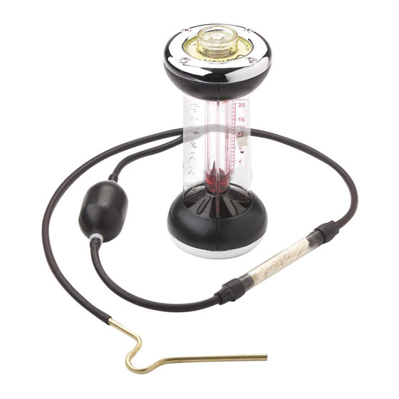
INSTRUCTIONS 0011-9026 OPERATION/MAINTENANCE BACHARACH FYRITE MODELS and O INDICATORS 1.0 DESCRIPTION (Refer to Figure 1) The FYRITE employs the well-known “Orsat” method of volumetric analysis involving chemical absorption of a sample gas, such as carbon dioxide or oxygen. The reagent... -
Page 6: Fyrite Fluid Handling Precautions
(b) FYRITE Fluid Strength To check fl uid strength. NOTE: When repeating procedures as outlined in Section 3.0 Steps 7 through 9 (absorbing and reading percent O and ab- sorbing and reading percent CO ) and before venting FYRITE to atmosphere for next sample, if the reading increases by more than 1/2 percent for either CO or O , replace the fl... -
Page 7: Basic Fyrite Operation Percent Co 2 And
HAZARDS Corrosive liquid causes burns. May cause blindness if splashed in eyes. Vapors are irritating and may be harmful. PRECAUTIONS Prevent contact with eyes, skin and clothing. Wear eye protection and gloves. Do not vent instrument until fl uid has drained from top well. Do not vent instrument (FY- RITE) in inverted position. - Page 8 FYRITE OPERATION FYRITE OPERATION (RED FLUID) (BLUE FLUID) 1. Hold upright (Fig. 1) and 1. Hold upright (Fig. 1) and away from face. Depress away from face. Depress Plunger Valve (momen- Plunger Valve (momen- tarily) to vent FYRITE, tarily) to vent FYRITE, and release.
- Page 9 FYRITE OPERATION FYRITE OPERATION (RED FLUID) (BLUE FLUID) 5. Holding FYRITE upright 5. Holding FYRITE upright (Fig. 5), loosen locknut at (Fig. 5), loosen locknut at rear of scale. Slide scale rear of scale. Slide scale (Fig. 5a) until top of fl uid (Fig.
- Page 10 FYRITE OPERATION FYRITE OPERATION (RED FLUID) (BLUE FLUID) 7. Absorb sample gas into 7. Absorb sample gas into FYRITE by inverting FYRITE by inverting until fl uid drains into top until fl uid drains into top reservoir (Fig. 7). Then reservoir (Fig.
-
Page 11: Determining Co And Ofyrite Fluid Strength
10. This step completes CO or O FYRITE gas sample analysis. A few points to re- member when reading the FYRITE: (a) FYRITE accuracy is within ±1/2% CO or O compared to actual value. (b) Always handle FYRITE by fi ns to ensure body heat is not absorbed by fl uid. (c) A delay in reading of 5 or 10 seconds may decrease accuracy of reading slightly but longer delays may cause substantial error. -
Page 12: Draining Fluid Droplets
3.2.1 Draining Fluid Droplets For maximum accuracy, it is important to form the habit of follow ing a standard procedure in this operation and to use the same procedure both before adjusting scale zero and before reading percent CO or O 3.3 FYRITE Temperature The FYRITE temperature should be at or close to the temperature of the working environment where the analysis is being made and should not be subject to sudden... -
Page 13: Principle Of Operation
4.0 PRINCIPLE OF OPERATION (Refer to Figures 12, 13, and 14) Figure 12. When plunger Figure 13. When plunger valve is depressed, a gas valve is released, the gas sample is pumped through sample is locked into FY- top reservoir with center RITE and the top reservoir bore is sealed off. -
Page 14: Application Information
To make a test with the FYRITE, the metal Sampling Tube at one end of Sampling Assembly Hose is inserted into the gas to be analyzed. The rubber Connector Plug at the other end of the Rubber Hose is then fi rmly pressed down on the spring-loaded Valve of the instrument (See Figure 12). -
Page 15: Instruction
FYRITE. 5.3 Typical FYRITE Applications Listed below are six models of FYRITE Indicators and two Aspirator Sampling Assem- blies with part numbers identifying their application. Bacharach Part Numbers For Test- Scale Aspirator Sam- Fluid... -
Page 16: Co Fyrite Only Combustion Testing
0-7.6% CO or O tests of controlled atmospheres in fruit, vegetable, and meat storage rooms. Oxygen determination in fl ammable gases. Oxygen tests to check atmospheres made inert with nitrogen (silos, fuel tanks, etc.) 0-20% CO or 0-21% O Flue gas combustion tests, oxygen defi ciency tests, and CO tests of heat treating atmospheres. -
Page 17: What Is Proper Co Value
(e.g., TEMPOINT) at the same sampling point. Deduct temperature of basement or combustion air supplied from measured fl ue gas tem- perature to obtain net fl ue gas temperature. Use a Bacharach FIRE EFFICIENCY FINDER to calculate combustion effi ciency. Instructions for using the FIRE EFFI- CIENCY FINDER are printed on the face of this slide rule calculator. -
Page 18: Measuring O
FYRITE metal Sampling Tube to be inserted as illustrated in Figure 17 to avoid dilu- tion of fl ue gas sample. Additional information on residential furnace combustion testing may be obtained from the following Bacharach publication: Bulletin 4097 - Technical Combustion Brochure 5.6 Background Gases Affecting FYRITE Readings... - Page 19 PERCENT EXCESS AIR Figure 15. Relation between Oxygen, CO and excess air in fl ue gases for Natural Gas and Fuel Oil. THEORETICAL EXCESS AIR CURVE STOICHIOMETRIC MIX Figure 16. CO measurements alone do not determine combustion air setting when fi ring gaseous fuels. Instruction 0011-9026 Page 15...
- Page 20 As a rule of thumb, background gases/vapors may be present in con centrations up to 1/2% by volume (5000 ppm) before they present a signifi cant interference problem to the CO or O FYRITE (20/21% ranges). An exception exists with the action of ammonia on Oxygen FYRITE Fluid. Ammonia neutralizes the acidic solution of chromous chloride, and therefore use of the O RITE with even trace amounts of ammonia in the backgrounds is not advised unless suitable fi...
-
Page 21: General Fyrite Applications
Figure 17. Checking CO of gas designed furnace (sampling tube inserted through draft diverter; fl ue gas temperature test can be made at same point). 5.7 General FYRITE Applications It is only possible to specify a few general rules for such applications. Where possible, sample should be obtained at a point where the gases are well mixed to a uniform composition. -
Page 22: Altitude Correction Table
The gas concentration read on the FYRITE is directly dependent upon the mass of air in the sample. The aspirator bulb used in the FYRITE is a constant-volume pump, not a constant-mass pump. Altitude, therefore, affects the FYRITE reading due to the air’s density changing with altitude, thus requiring higher CO or O concentrations to... -
Page 23: Checking Fyrite Fluid Strength
Refer to Figure 19. To remove excess fl uid, insert small diameter glass tube into FY- RITE fl uid through the small center FYRITE bore (with Top Cap Assembly removed). Seal open end of glass tube with fi nger and dip out fl uid with glass tube until FYRITE fl... - Page 24 ® ® Figure 18. Increasing FYRITE Figure 19. Decreasing FYRITE fl uid to proper level. fl uid to proper level TOP GASKET TOP CAP/ PLUNGER VALVE ASSEMBLY ® ® OVAL HEAD SCREWS TOP CAP RING WITH GASKET Figure 20. Removing top gasket. Figure 21.
-
Page 25: Fyrite Fluid Only
accuracy don’t forget to saturate fi lter saturator wool packing as such gas standards are usually supplied “bone dry”. 6.2.2 O FYRITE Fluid Only Fresh FYRITE fl uid will absorb all O from approximately 100 samples containing 10% O . After completing test (as outlined in Section 3.0 Steps 1 through 9) O RITE Fluid strength can be checked by performing steps outlined below: DO NOT VENT FYRITE, but reabsorb sample gas into FYRITE by inverting until fl... -
Page 26: Inspection Of Fyrite For Fluid Leakage
Drain old fl uid from FYRITE and rinse all parts in clean, lukewarm water. NOTE: FYRITE fl uid is corrosive to skin, clothing, some met- als, and painted or lacquered surfaces. Dispose of these fl uids in accordance with Local, State and Federal Laws. If draining into a porcelain sink is permitted, keep water faucet turned on while draining and fl... - Page 27 ® % CO Figure 21a. Alternate fi lling meth- Figure 22. Examining top gasket od. Invert FYRITE (with bottle in for warpage. place) to upright position. TOP CAP ASSEMBLY GASKET BODY ® Top Gasket used in 7%, 20% & 21% Models only ®...
-
Page 28: Cleaning Fyrite
mine replacement parts necessary for repair, or drain instrument and return if factory service or repair is desired. 6.5 Cleaning FYRITE Use only soapy lukewarm water if cleaning is required (lukewarm water is usually suffi cient). NOTE: Use of gasoline, naptha, carbon tetrachloride or any other organic solvent or oil will destroy plastic and rubber parts. - Page 29 LETTERING BOTTOM CAP ® (RECESS) %CO2 Figure 25a. Replacement Diaphragm properly installed. Figure 26. FYRITE Sampling Assembly; Figure 25. Locating Bezel Locating Inlet/Outlet Check Valves. Rubber Gaskets. Instruction 0011-9026 Page 25...
-
Page 30: Storing Fyrite And Refi Ll Fluid
A recommended practice is to accumulate stock only suffi cient for one year requirement and to use oldest stock fi rst. Fluid can be tested for performance accord- ing to Section 6.2. Use only Bacharach CO or O Fluid Refi lls for the range FYRITE selected. The Kits below contain three Refi... - Page 31 RUBBER CONNECTOR TIP (HOLD FINGER HERE) ASPIRATOR BULB SHOULD REMAIN FIRM WHEN SQUEEZED Figure 27. Testing Sampling Assembly (outlet side) for leaks. CHECK FOR BULB INFLATION AFTER SQUEEZING SAMPLING TUBE END (HOLD FINGER HERE) Figure 28. Testing Sampling Assembly (inlet side) for leaks. Figure 29.
- Page 32 Figure 30. Wrapping Replacement Filter Material. Figure 31. Wet Filter Material then squeeze out excess water. Figure 32. Installing wetted Filter Material into Saturator Tube. Page 28 Instruction 0011-9026...
- Page 33 Part # Description Qty-Rq’d 11-0102 Bezel 11-0188 Oval Head Screw 11-0110 Bezel Screw 11-0109 Top Cap Ring Gasket (Optional, Part of 11-0136) 11-0105 Scale Screw 02-3690 Scale Screw Nut 11-0021 Diaphragm 11-0126 Bottom Cap 11-0132 Top Cap 11-0019 Valve Plunger 11-0026 Valve Plunger Spring 11-0020...
-
Page 34: Fyrite Illustrated Parts
7.1 FYRITE ILLUSTRATED PARTS 11-0062 11-0019 05-5169 11-0102 11-0026 11-0188 05-5155 11-0136 11-0188 11-0109 11-0132 11-0143 (7%, 20%, and 21% Models Only) 11-0102 11-0020 11-0110 05-5134 02-3690 05-5134 11-0110 11-0140 11-0102 11-0110 11-0154 11-0021 11-0126 11-0110 11-0102 11-0188 Figure 33. FYRITE parts breakout. Page 30 Instruction 0011-9026... -
Page 35: Fyrite Sampling Assemblies
7.2 PARTS LIST FOR FYRITE SAMPLING ASSEMBLIES STANDARD SAMPLING ASSEMBLY Part No. 11-7029 Gases saturated with water vapor (combustion products). Dry gases when fi lter material is wetted. 0011-0122 0011-0118 0011-0106 (0011-0180 + 0011-0130) 0011-0120 0011-0152 0011-0118 0011-0138 0011-0138 0011-0119 Instruction 0011-9026 Page 31... - Page 36 Current Former Part # List # Description # Req'd 11-0152 10-0019 Connector Tip with Tube 11-0156 10-0029 Rubber Tubing, 10' Length 11-0118 10-0020 Rubber Tubing, 6" Length 11-0165 10-0030 Filter Tube, Aluminum 19-5004 19-9004 Gas Collecting Bladder with Orifi ce 11-0120 10-0022 Aspirator Bulb...
- Page 37 Notes Instruction 0011-9026 Page 33...
- Page 38 Notes Page 34 Instruction 0011-9026...
- Page 39 Notes Instruction 0011-9026 Page 35...
- Page 40 Bacharach, Inc. 621 Hunt Valley Circle, New Kensington, PA 15068 Phone: 724-334-5000 • Fax: 724-334-5001 • Toll Free: 800-736-4666 Web: www.mybacharach.com • E-mail: help@mybacharach.com Page 36 Instruction 0011-9026...
Need help?
Do you have a question about the FYRITE Gas Analyzer CO2 and O2 Indicators and is the answer not in the manual?
Questions and answers